EP1481223B1 - Gerät und verfahren zum messen von parametern einer in einer leitung strömenden mischung, die in einem dampf suspendierte flüssigkeitströpfchen enthält - Google Patents
Gerät und verfahren zum messen von parametern einer in einer leitung strömenden mischung, die in einem dampf suspendierte flüssigkeitströpfchen enthält Download PDFInfo
- Publication number
- EP1481223B1 EP1481223B1 EP03713789.0A EP03713789A EP1481223B1 EP 1481223 B1 EP1481223 B1 EP 1481223B1 EP 03713789 A EP03713789 A EP 03713789A EP 1481223 B1 EP1481223 B1 EP 1481223B1
- Authority
- EP
- European Patent Office
- Prior art keywords
- mixture
- pipe
- pressure
- vapor
- vortical
- Prior art date
- Legal status (The legal status is an assumption and is not a legal conclusion. Google has not performed a legal analysis and makes no representation as to the accuracy of the status listed.)
- Expired - Lifetime
Links
Images


Classifications
-
- G—PHYSICS
- G01—MEASURING; TESTING
- G01F—MEASURING VOLUME, VOLUME FLOW, MASS FLOW OR LIQUID LEVEL; METERING BY VOLUME
- G01F1/00—Measuring the volume flow or mass flow of fluid or fluent solid material wherein the fluid passes through a meter in a continuous flow
- G01F1/74—Devices for measuring flow of a fluid or flow of a fluent solid material in suspension in another fluid
-
- G—PHYSICS
- G01—MEASURING; TESTING
- G01F—MEASURING VOLUME, VOLUME FLOW, MASS FLOW OR LIQUID LEVEL; METERING BY VOLUME
- G01F1/00—Measuring the volume flow or mass flow of fluid or fluent solid material wherein the fluid passes through a meter in a continuous flow
- G01F1/66—Measuring the volume flow or mass flow of fluid or fluent solid material wherein the fluid passes through a meter in a continuous flow by measuring frequency, phase shift or propagation time of electromagnetic or other waves, e.g. using ultrasonic flowmeters
- G01F1/666—Measuring the volume flow or mass flow of fluid or fluent solid material wherein the fluid passes through a meter in a continuous flow by measuring frequency, phase shift or propagation time of electromagnetic or other waves, e.g. using ultrasonic flowmeters by detecting noise and sounds generated by the flowing fluid
-
- G—PHYSICS
- G01—MEASURING; TESTING
- G01F—MEASURING VOLUME, VOLUME FLOW, MASS FLOW OR LIQUID LEVEL; METERING BY VOLUME
- G01F1/00—Measuring the volume flow or mass flow of fluid or fluent solid material wherein the fluid passes through a meter in a continuous flow
- G01F1/66—Measuring the volume flow or mass flow of fluid or fluent solid material wherein the fluid passes through a meter in a continuous flow by measuring frequency, phase shift or propagation time of electromagnetic or other waves, e.g. using ultrasonic flowmeters
- G01F1/667—Arrangements of transducers for ultrasonic flowmeters; Circuits for operating ultrasonic flowmeters
- G01F1/668—Compensating or correcting for variations in velocity of sound
-
- G—PHYSICS
- G01—MEASURING; TESTING
- G01F—MEASURING VOLUME, VOLUME FLOW, MASS FLOW OR LIQUID LEVEL; METERING BY VOLUME
- G01F1/00—Measuring the volume flow or mass flow of fluid or fluent solid material wherein the fluid passes through a meter in a continuous flow
- G01F1/704—Measuring the volume flow or mass flow of fluid or fluent solid material wherein the fluid passes through a meter in a continuous flow using marked regions or existing inhomogeneities within the fluid stream, e.g. statistically occurring variations in a fluid parameter
- G01F1/708—Measuring the time taken to traverse a fixed distance
- G01F1/7082—Measuring the time taken to traverse a fixed distance using acoustic detecting arrangements
-
- G—PHYSICS
- G01—MEASURING; TESTING
- G01F—MEASURING VOLUME, VOLUME FLOW, MASS FLOW OR LIQUID LEVEL; METERING BY VOLUME
- G01F1/00—Measuring the volume flow or mass flow of fluid or fluent solid material wherein the fluid passes through a meter in a continuous flow
- G01F1/704—Measuring the volume flow or mass flow of fluid or fluent solid material wherein the fluid passes through a meter in a continuous flow using marked regions or existing inhomogeneities within the fluid stream, e.g. statistically occurring variations in a fluid parameter
- G01F1/708—Measuring the time taken to traverse a fixed distance
- G01F1/712—Measuring the time taken to traverse a fixed distance using auto-correlation or cross-correlation detection means
-
- G—PHYSICS
- G01—MEASURING; TESTING
- G01N—INVESTIGATING OR ANALYSING MATERIALS BY DETERMINING THEIR CHEMICAL OR PHYSICAL PROPERTIES
- G01N2291/00—Indexing codes associated with group G01N29/00
- G01N2291/02—Indexing codes associated with the analysed material
- G01N2291/028—Material parameters
- G01N2291/02836—Flow rate, liquid level
-
- G—PHYSICS
- G01—MEASURING; TESTING
- G01N—INVESTIGATING OR ANALYSING MATERIALS BY DETERMINING THEIR CHEMICAL OR PHYSICAL PROPERTIES
- G01N2291/00—Indexing codes associated with group G01N29/00
- G01N2291/02—Indexing codes associated with the analysed material
- G01N2291/028—Material parameters
- G01N2291/02872—Pressure
Definitions
- This invention relates to an apparatus for measuring the flow passing within a pipe, and more particularly to an apparatus and method for measuring the speed of sound and/or vortical disturbances propagating in the flow, particles suspended within a continuous fluid comprising a vapor/liquid mixture, to determine parameters, such as flow "wetness", vapor/liquid quality, particle size, mass flow, enthalpy and volumetric flow rate of the vapor/liquid flow in pipes using acoustic and/or dynamic pressures.
- This invention provides an apparatus and method to measure saturated vapor / liquid mixtures used in industrial systems having various working fluids, such as in chemical, pharmaceutical, paper/pulp, petroleum and power generation industries.
- vapor quality e.g., steam quality
- wetness of the mixture.
- Vapor quality of a saturated vapor/liquid mixture is defined as the ratio of the mass of the vapor phase to the total mass of the mixture.
- the "wetness" of a saturated vapor/liquid mixture is defined as the ratio of the mass of the liquid phase to the total mass of the mixture.
- Saturated mixtures exist at temperatures and pressures at which liquid and vapor phases coexist.
- the temperatures and pressures at which the liquid and vapor phases coexist lie under the "vapor bubble" (i.e., saturation lines) on a phase diagram.
- a representative phase diagram for water is shown in Fig. 1 .
- the collection of points known as the saturated liquid line and the collections of points known as the saturated vapor line define the vapor bubble. These two lines connect at, what is termed, the critical point.
- Saturated mixtures exist only under the vapor bubble.
- the fluid exists as a single phase and the properties of that fluid, such as density, enthalpy, internal energy, etc., are uniquely defined by the pressure and temperature.
- these properties are tabulated as functions of pressure and temperatures and are available through a variety of references including a website hosted by NIST (ref: http://webbook.nist.gov/chemistry/fluid/) .
- the fluids represent mixtures of the liquid and vapor phase.
- the properties of both the vapor and liquid phases are well defined (and tabulated for known substances)
- the properties of the mixture are no longer uniquely defined as functions of pressure and temperature.
- the ratio of the vapor and liquid components of the mixture must be defined.
- the quality of the mixture, in addition to the pressure and temperature, are defined and used to uniquely determine the properties of the mixture.
- Measuring the average properties of a mixture is important in many industrial application since it is the mass averaged properties of the working fluid that enter directly into monitoring the thermodynamic performance of many processes. For example, it is the difference in the flux of enthalpy of the steam mixture flowing into and exiting from a turbine that determines the maximum mechanical work that can be extracted from the working fluid, and thus is important to determine component efficiency.
- pressure and temperature measurement would not be sufficient to determine the specific enthalpy, but rather, a measurement of the quality of the steam would be required to uniquely define the thermodynamic properties of the saturated steam mixture. Note that once the quality and pressure (or temperature) of a saturated mixture is defined, the thermodynamic properties of the mixture are defined through mixing laws provided the properties of the liquid and vapor sates are known.
- the present invention provides the means for measuring the speed of sound enables one to determine quality, which in turn enables one to calculate enthalpy, density, and other properties of the mixture.
- a measurement of the total mass is also, in general, needed to determine the flux of enthalpy.
- the quality of the steam within the steam turbine affects blade life. Generally it is desired to operate so the quality is as high as possible throughout the turbine to minimize liquid water drops that will erode the metal blades. Knowing the quality at the turbine inlet and exhaust (or at the exhaust only if the inlet is super-heated) provides a means to monitor the quality throughout the turbine. Also, to monitor plant performance so that it can be operated at optimum conditions and to identify degradation effects, the steam turbine thermal performance must be known. This requires the fluid enthalpy at the inlet and exhaust of each turbine to be known. If the fluid at either or both locations is saturated, pressure and temperature measurements alone will not be enough to determine the enthalpy. However if an additional measurement of quality is made the enthalpy is then defined. In addition, there may be other applications in refrigeration cycles.
- the ability to measure the flow rate and composition of the saturated vapor / liquid mixtures within the conduits is an important aspect of any system or strategy design to optimize the performance of a system based on saturated vapor/liquid mixtures.
- the industry recognizes this, and has been developing a wide variety of technologies to perform this measurement. These include probe based devices, sampling devices, venturis and ultrasonic devices
- Objects of the present invention include providing a system for measuring the speed of sound propagating through a vapor/liquid mixture in pipes in industrial processes and other related processes, for example, to determine particular parameters of the mixture.
- the invention is directed to an apparatus and method according to the independent claims.
- An apparatus for measuring at least one parameter of a vapor/liquid mixture in a pipe includes a spatial array of at least two pressure sensors, disposed at different axial locations along the pipe. Each of the pressure sensors measures an unsteady pressure within the pipe at a corresponding axial location. Each of said sensors provides a pressure signal indicative of the unsteady pressure within the pipe at said axial location of a corresponding one of said sensors. A signal processor, responsive to said pressure signals, provides a signal indicative of the at least one parameter of the mixture in the pipe.
- a method for measuring at least one parameter of a vapor/liquid mixture in a pipe includes measuring unsteady pressures within the pipe at least two predetermined axial measurement locations along the pipe to provide a pressure signal indicative of the unsteady pressure within the pipe at each of the at least two predetermined axial measurement locations. Further the method includes calculating the at least one parameter of the particle/fluid mixture in the pipe using the unsteady pressure measured at the axial measurement locations.
- a power plant 1 includes, by way of example, at least one flow meter 8 in accordance with the present invention to determine various parameters of the saturated vapor/liquid mixture, wherein one of the parameters is the speed at which sound travels within the saturated vapor/liquid mixtures pipe system as will be more fully described herein below.
- a flow meter 10,70 embodying the present invention measures a number of parameters/characteristics of a saturated vapor/liquid mixture 12 of liquid droplets suspended within a continuous vapor/gas flowing within a pipe or conduit 14.
- the flow meter may be configured and programmed to measure the speed of sound propagating through the saturated vapor/liquid mixture or measure the vortical disturbances propagating through the vapor/liquid mixture.
- the flow meter 10 may be configured to measure both the speed of sound and the vortical disturbances.
- the flow meter can measure at least one of the following parameters of the mixture flow 12: the wetness or steam quality (volumetric phase fraction), the volumetric flow rate, the size of the liquid particles, the mass flow, the enthalpy and the velocity of the mixture.
- the flow meter 10,70 measures the unsteady pressures created by the speed of sound (SOS) and/or the vortical disturbances propagating through the vapor/liquid mixture flowing in the pipe 14, which will be described in greater detail hereinafter.
- SOS speed of sound
- the liquid droplets of the mixture 12 may be of any size, shape and liquid.
- the size of the droplets may be as small as ⁇ 0.3 ⁇ m in length (or diameter) to greater than 50 ⁇ m.
- the flow meter 10,70 can be used in any application that carries liquid droplets suspended in a vapor/gas through a pipe, such as in paper/pulp, petroleum and power generation applications.
- the present invention is well suited to measure the parameters (e.g. vapor/liquid ratio, particle size) for power generation systems.
- a representative steam delivery system 1 is shown in a power generation system 2 in Fig. 2 .
- the flow meter 10,70 of the present invention may be configured and programmed to measure and process the detected unsteady pressures P 1 (t) - P N (t) created by acoustic waves and/or vortical disturbances propagating through the mixture to determine parameters of the mixture flow 12.
- One such flow meter 10 is shown in Fig. 3 that measures the speed of sound (SOS) of one-dimensional sound waves propagating through the vapor/liquid mixture to determine the composition the mixture, namely the "wetness" or steam quality of the mixture.
- the flow meter is also capable of determining the average size of the droplets, velocity of the mixture, enthalpy, mass flow, density, and the volumetric flow rate of the mixture.
- the speed of sound of a mixture within a pipe 14 may be determined using a number of known techniques, such as those set forth in U.S. Patent Application Serial No. 09/344,094 , entitled “Fluid Parameter Measurement in Pipes Using Acoustic Pressures", filed June 25, 1999, and U.S. Patent Application Serial No. 10/007,749 , entitled “Fluid Parameter Measurement in Pipes Using Acoustic Pressures", filed November 7, 2001, each of which are incorporated herein by reference.
- the present invention utilizes at least one flow meter 10 to determine various parameters of the saturated vapor/liquid mixture, wherein one of the parameters is the speed at which sound travels within in the mixture pipe system, as will be more fully described herein below.
- the speed of sound propagating through the vapor/liquid mixture 12 is measured by passively listening to the flow with an array of unsteady pressure sensors to determine the speed at which one-dimensional compression waves propagate through a vapor/liquid mixture contained within the pipe 14.
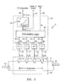
- the flow meter 10 has an array of at least three acoustic pressure sensors 15,16,17, located at three locations x 1 ,x 2 ,x 3 axially along the pipe 14.
- the sensor array may include more than three pressure sensors as depicted by pressure sensor 18 at location x N .
- the pressure generated by the acoustic waves may be measured through holes in the pipe 14 ported to external pressure sensors 15 - 18 or by other techniques discussed hereinafter.
- the pressure sensors 15 - 18 provide pressure time-varying signals P 1 (t),P 2 (t),P 3 (t),P N (t) on lines 20,21,22,23 to a signal processing unit 30 to known Fast Fourier Transform (FFT) logics 26,27,28,29, respectively.
- the FFT logics 26 - 29 calculate the Fourier transform of the time-based input signals P 1 (t) - P N (t) and provide complex frequency domain (or frequency based) signals P 1 ( ⁇ ),P 2 ( ⁇ ),P 3 ( ⁇ ),P N ( ⁇ ) on lines 32,33,34,35 indicative of the frequency content of the input signals.
- any other technique for obtaining the frequency domain characteristics of the signals P 1 (t) - P N (t) may be used.
- the cross-spectral density and the power spectral density may be used to form a frequency domain transfer functions (or frequency response or ratios) discussed hereinafter.
- the frequency signals P 1 ( ⁇ ) - P N ( ⁇ ) are fed to a mix -Mx Calculation Logic 38 which provides a signal to line 40 indicative of the speed of sound of the vapor/liquid mixture a mix (discussed more hereinafter).
- the a mix signal is provided to map (or equation) logic 42, which converts a mix to a percent composition of the vapor/liquid mixture and provides a %Comp signal to line 44 indicative thereof (as discussed hereinafter).
- the calculation logic 40 may also provide a signal Mx to line 46 indicative of the Mach number Mx.
- the acoustic pressure field P(x,t) at a location x along a pipe where the wavelength ⁇ of the acoustic waves to be measured is long compared to the diameter d of the pipe 12 (i.e., ⁇ /d>>1), may be expressed as a superposition of a right traveling wave and a left traveling wave, as follows:
- P x t A e i k r ⁇ x + B e i k l ⁇ x ⁇ e i ⁇ ⁇ ⁇ t
- A,B are the frequency-based complex amplitudes of the right and left traveling waves, respectively
- x is the pressure measurement location along a pipe
- k r ,k l are wave numbers for the right and left traveling waves, respectively, which are defined as: k r ⁇
- the data from the array of sensors may be processed in any domain, including the frequency/spatial domain, the temporal/spatial domain, the temporal/wave-number domain or the wave-number/frequency (k- ⁇ ) domain.
- any known array processing technique in any of these or other related domains may be used if desired, similar to the techniques used in the fields of SONAR and RADAR.
- signal processing unit 30 may be implemented in software (using a microprocessor or computer) and/or firmware, or may be implemented using analog and/or digital hardware, having sufficient memory, interfaces, and capacity to perform the functions described herein.
- Acoustic pressure sensors 15 - 18 sense acoustic pressure signals that, as measured, are lower frequency (and longer wavelength) signals than those used for ultrasonic flow meters of the prior art, and thus the current invention is more tolerant to inhomogeneities in the flow, such as time and space domain inhomogeneities within the flow.
- the present invention incorporates the compliance of the pipe 14 to determine the effective speed of sound of the vapor/liquid mixture flowing through the pipe.
- the acoustic pressure signals P 1 (t) - P N (t) are generated within the vapor/liquid mixture of the pipe 14 by a variety of non-discrete sources such as remote machinery, mills, pumps, valves, elbows, as well as the vapor/liquid mixture flow itself. It is this last source, the vapor/liquid mixture 12 flowing within the pipe 14, which is a generic source of acoustic noise that assures a minimum level of acoustics for any vapor/liquid mixture piping systems for which the present invention takes unique advantage.
- the flow generated acoustics increase with mean flow velocity and the overall noise levels (acoustic pressure levels) are a function of the generating mechanism and the damping mechanism. As such, no external discrete noise source is required within the present invention and thus may operate using passive listening. While the flow meter 10 passively listens to the mixture flow 12, the present invention contemplates adding an acoustic source to inject a desire acoustic wave into the flow to be measured, such as by compressing, vibrating and/or tapping the pipe, to name a few examples.
- the pipe 14 may be desirable for the pipe 14 to exhibit a certain amount of pipe compliance.
- the axial test section 50 of the pipe 14 along where the sensors 15 - 18 are located may be made as rigid as possible.
- the thickness of the wall of the test section 50 may be made to have a predetermined thickness, or the test section 50 may be made of a very rigid material, e.g., steel, titanium, Kevlar ® , ceramic, or other material with a high modulus.
- the pressure sensor spacing may be known or arbitrary and that as few as two sensors are required if certain information is known about the acoustic properties of the vapor/liquid mixture piping system.
- the pressure sensors are spaced sufficiently such that the entire length of the array (aperture) is at least a significant fraction of the measured wavelength of the acoustic waves being measured.
- the acoustic wavelength to be measured is a function of at least the size and mass of the droplets, and the viscosity of the vapor. The greater the size and mass of the droplets and/or the less viscous the vapor, the greater the spacing of the sensors is needed. Conversely, the smaller the size and mass of the droplets and/or the more viscous the vapor, the shorter the spacing of the sensors is needed.
- mist flow For relatively well-mixed vapor / liquid mixtures in which the liquid phase exists as small droplets within a continuous gas phase, the flow can be termed mist flow.
- the compliance introduced by the pipe reduces the measured sound speed from the infinite dimensional sound speed.
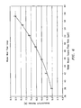
- Fig. 4 shows the actual measured speed of sound data as a function of frequency for air flowing through a pipe 14.
- the pipe was part of a water mist flow loop includes 0.38 m (15 inch) diameter piping havng a 9.15 m (30 foot) test section with 10 sensors in the array.
- the water droplets were formed by atomizing nozzles spraying approximately 1 GPM having a droplet size of 20-30 um.
- a fan propagated the droplets through the mist loop at approximately 1200 CFM. As would be expected, the speed of sound over the measured frequency range is substantially linear.
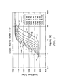
- Fig. 5 shows the actual measured speed of sound data as a function of frequency for a water mist 12 (vapor/liquid mixture) flowing through the same pipe 14 of the water mist flow loop.
- the sound speed was measured utilizing passive listening techniques of the present invention as described herein.
- the frequency dependence of the sound speed was determined by applying a Capon array-processing algorithm at multiple narrow frequency ranges between 50-300 Hz thereby determining a frequency specific acoustic propagation velocity.
- the sound speed increases with increasing frequency and asymptotes toward a constant value.
- the sound speed asymptote at higher frequency is essentially the sound speed of air only with no influence of the suspended liquid droplets.
- the sound speed of the vapor/liquid mixture has not reached the quasi-steady limit at the lowest frequency for which sound speed was measured.
- the sound speed is continuing to decrease at the lower frequency limit.
- An important discovery of the present invention is that the speed at which sound propagates through droplets suspended in a continuous vapor is said to be dispersive. As defined herein, the speed at which acoustic waves propagate through dispersive mixtures varies with frequency.
- Fig. 6 further shows the actual measure wetness as a function to the water nozzle supply flow rate which shows the wetness increase as the input flow rate of the nozzles increase, as one would expect.
- ⁇ x aperture which define the aperture of the array
- the aperture should be at least a significant fraction of a wavelength of the sound speed of interest. Consequently, longer arrays are used to resolve sound speeds at lower frequencies, which will be described in greater detail hereinafter.
- the standard deviation associated with determining the speed of sound in air is shown as a function of frequency for three arrays of varying aperture, namely 0.46, 0.91 and 3.05 m (1.5 ft, 3 ft and 10 ft).
- the data suggests that utilizing a quasi-steady model to interpret the relationship between sound speed, measured at frequencies above those at which the quasi-steady model is applicable, and the liquid-to-vapor ratio would be problematic, and may, in fact, be impractical.
- the key to understanding and interpreting the composition of vapor/liquid mixtures through sound speed measurements lies in the dispersive characteristics of the vapor/liquid mixture.
- the dispersive nature of the system utilizes a first principles model of the interaction between the vapor and liquid droplets.
- This model is viewed as being representative of a class of models that seek to account for dispersive effects.
- Other models could be used to account for dispersive effects without altering the intent of this disclosure (for example, see the paper titled "Viscous Attenuation of Acoustic Waves in Suspensions" by R.L. Gibson, Jr. and M.N. Toksöz), which is incorporated herein by reference.
- the model allows for slip between the local velocity of the continuous vapor phase and that of the droplets.
- the drag force on the droplets by the continuous vapor is modeled by a force proportional to the difference between the local vapor velocity and that of the liquid droplets and is balanced by inertial force:
- K proportionality constant
- U f fluid velocity
- U p liquid droplet velocity
- ⁇ p liquid droplet density
- v p particle volume.
- the effect of the force on the continuous vapor phase by the liquid droplets is modeled as a force term in the axial momentum equation.
- P pressure at locations x and ⁇ x
- ⁇ p volume fraction of the liquid droplets
- ⁇ f vapor density.
- the fluid SOS, density (p) and viscosity ( ⁇ ) are those of the pure phase fluid, v p is the volume of individual droplets and ⁇ p is the volumetric phase fraction of the droplets in the mixture.
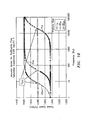
- Figs. 8 and 9 show the dispersive behavior for vapor/liquid mixtures with parameters typical of those used in steam flow systems.
- Fig. 8 shows the predicted behavior for nominally 50 ⁇ m size liquid droplets in vapor for a range of liquid-to-vapor ratios.
- the effect of liquid-to-vapor ratio is well defined in the low frequency limit.
- the effect of the liquid-to-vapor ratio becomes indistinguishable at higher frequencies, approaching the sound speed of the pure air at high frequencies (above ⁇ 100 Hz).
- Fig. 9 shows the predicted behavior for a vapor/liquid mixture with a liquid-to-vapor ratio of 1.8 with varying liquid droplet size. This figure illustrates that liquid droplet size has no influence on either the low frequency limit (quasi-steady) sound speed, or on the high frequency limit of the sound speed. However, droplet size does have a pronounced effect in the transition region.
- Figs. 8 and 9 illustrate an important aspect of the present invention. Namely, that the dispersive properties of mixtures of droplets suspended in a continuous vapor can be broadly classified into three frequency regimes: low frequency range, high frequency range and a transitional frequency range.
- the effect of droplet size and liquid-to-vapor ratio are inter-related, the predominant effect of liquid-to-vapor ratio is to determine the low frequency limit of the sound speed to be measured and the predominate effect of droplet size is to determine the frequency range of the transitional regions.
- the frequency at which the dispersive properties appear decreases. For typical steam applications, this transitional region begins at fairly low frequencies, ⁇ 2Hz for 50 ⁇ m size particles.
- the frequency range for which the no-slip, quasi-steady approximation is valid is a function of a variety of parameters including droplet size, continuous phase viscosity, droplet shape and droplet density.
- VLR vapor/liquid ratio
- droplet size does not affect the low frequency limit of the sound speed.
- Fig. 10 shows the predicted behavior for a saturated vapor/liquid mixture with a liquid-to-vapor ratio with varying droplet size.
- the particle sizes of three different mixtures include 50 um, 20 um and lum.
- the transitional frequency range of the mixture having 50 um droplets is approximately 3- 13 Hz, a central frequency (f 1/2 ) of approximately 8 Hz.
- the transitional frequency range of the mixture having 20um droplets is approximately 11 - 110 Hz, a central frequency (f 1/2 ) of approximately 60 Hz.
- the transitional frequency range of the mixture having 1 um is approximately 8 - 80 KHz, a central frequency (f 1/2 ) of approximately 40 degrees.
- the droplet size greatly influences the dispersion characteristics of the saturated vapor/liquid mixture.
- the transistion from the quasi-steady state to the high frequency regime scales inversely with the square of the droplet diameter.
- the dispersion characteristics set the frequency requirements for measuring the speed of sound propagating through the mixture to measure parameters of the mixture.
- the frequency of the speed of sound that is detected for a particular mixture sets the wavelength of interest.
- the wavelength is the inverse of the frequency, and therefore, the higher the frequency, the shorter the wavelength and vice versa.
- the wavelength therefore, defines the aperture ( ⁇ x aperture ) of the array 50 (See Fig. 3 ).
- the aperture should be at least a significant fraction of the length of the wavelength of the speed of sound of interest.
- a vapor/liquid mixture having droplets of approximately 30 um has a central frequency (f 1/2 ) of approximately 30 Hz, which corresponds to an aperture of approximately 6.1 m (20 ft).
- a vapor/liquid mixture having droplets of approximately 3 um has a central frequency (f 1/2 ) of approximately 3 KHz, which corresponds to an aperture of approximately 0.3 m (1 ft). Consequently, the size of the liquid droplet defines the length of the aperture of the flow meter. In other words, the larger the size of the droplet, the longer the aperture needed to measure the speed of sound to determine specific parameters of the mixture. Similarly, the smaller the size of the droplet, the shorter the aperture needed to measure the speed of sound to determine specific parameters of the mixture.
- the dispersion relation predicts the sound speed with asymptote towards the sound speed of the pure vapor.
- the high frequency limit is independent of both droplet size and liquid-to-vapor ratio.
- the flow meter 10 of the present invention includes the ability to accurately determine the average droplet size of the liquid in the vapor/liquid mixture within the pipe 14 and the liquid/vapor ratio.
- the propagation of one-dimensional sound wave through multiphase mixtures is influenced by the effective mass and the effective compressibility of the mixture.
- the degree to which the no-slip assumption applies is a strong function of droplet size and frequency. In the limit of small droplets and low frequency, the no-slip assumption is valid. As the size of the droplet increases and the frequency of the sound waves increase, the non-slip assumption becomes increasing less valid.
- the increase in slip with frequency causes dispersion, or, in other words, the sound speed of the mixture to change with frequency.
- dispersive characteristic of a mixture will provide a measurement of the average droplet size, as well as, the vapor to liquid ratio of the mixture.
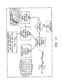
- Fig. 11 there is shown an optimization procedure in accordance with the present invention in which the free parameters of an analytical model are optimized to minimize an error function.
- the sound speed of a two-phase mixture varies with the ratio vapor and liquid phases present in the mixture.
- the Wood equation is an engineering approximation, the accuracy of which is dependent on the validity of a variety of assumptions.
- Experimental data may be required to define between quality and sound speed within required, but to be defined, accuracy limits.
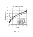
- Various curves are produced in Fig. 12 showing the relationship of sound speed versus steam quality for well-mixed saturated steam mixtures over of range of temperatures and pressures.
- determining the enthalpy flux of a steam mixture is an important measurement.
- the enthalpy per unit volume of the mixture is needed to determine the total flow rate.
- Fig. 14 shows the relationship between enthalpy per unit volume and mixture sound speed for steam at a variety of conditions.
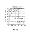
- the present invention further utilizes the relationship between enthalpy per unit volume and mixture sound speed for steam at a variety of conditions and the relationship between enthalpy per unit volume and steam quality as shown in Fig. 15 to determine the quality of steam in a pipe 12.
- the flow meter 10 further includes the ability to measure of volumetric flow rate of the mixture by comparing the difference of the speed of one dimensional sound waves propagating with and against the mean flow.
- This method of determining the volumetric flow rate of the vapor/liquid mixture 12 within pipe 14 relies on the interaction of the mean flow with the acoustic pressure field.
- a L velocity of a left traveling acoustic wave apparent to a stationary observer
- a mix speed of sound traveling through the mixture (if the mixture was not flowing)
- u the mean flow velocity (assumed to be flowing from left to right in this instance).
- the mean flow velocity can be calculated by multiplying the mean flow velocity by the cross-sectional area of the pipe 14.
- the flow meter 10 utilizes similar processing algorithms as those employed herein before, and described in greater detail in.
- ⁇ is the temporal frequency in rad/sec
- a mix is the speed at which sound propagates within the process piping.
- the acoustic power is located along two acoustic ridges, one for the sound traveling with the flow at a speed of a mix + V mix and one for the sound traveling against the flow at a speed of a mix - V mix .
- Fig. 16 shows a k- ⁇ plot generated for acoustic sound field of a vapor/liquid mixture flowing through a pipe. Two acoustic ridges are clearly evident. Each of the slopes of the two depicted acoustic ridges respectively defines the speed of sound traveling with and against the mean flow.
- Fig. 16 illustrates the ability of the present invention to determine the velocity of a fluid moving in a pipe.
- the figures are plots of data from an actual test run of a flowmeter in accordance with the invention as described herein above.
- Figure 9 shows a wavenumber-frequency plot (k-w plot) of unsteady pressure data collected with a flowmeter 8 of the present invention comprising a 4-sensor axial array in an atmospheric pressure loop flowing air at a velocity of approximately 12.2 m/s (40 ft/sec).
- the color contours represent the relative signal power at all combinations of frequency and wavenumber.
- the highest power "ridges" represent the acoustic wave with slope of the ridges equal to the propagation speed.
- the acoustic ridges "wrap" to the opposite side of the plot at the spatial Nyquist wavenumber equal to ⁇ 3.14 in this case (i.e. the acoustic ridge that slopes up and to the right starting at the bottom of the plot, the right-side ridge, wraps to the left side of the plot at approximately 550 Hz and continues sloping up and to the right).
- the dashed lines show the best-fit two-variable maximization of the power with the two variables being sound speed and flow velocity.
- the right-side ridge represents the acoustic wave traveling in the same direction as the bulk flow and therefore its slope is steeper than the left-side ridge that represents the acoustic wave traveling in the opposite direction of the bulk flow. This indicates that the acoustic wave traveling in the same direction of the flow is traveling faster than the acoustic wave traveling in the opposite direction of the bulk flow relative to the stationary sensors located on the pipe.
- the sonar flow meter 10 of Fig. 3 is configured and programmed to measure and utilize the speed of sound propagating through a vapor/liquid mixture 12 flowing in a pipe 14 to determine volumetric flow rate.
- a flow meter 70 embodying the present invention includes the ability to measure volumetric flow rate of the mixture by measuring the unsteady pressures generated by vortical disturbance 88 propagating in the mixture.
- the flow meter 70 uses one or both of the following techniques to determine the convection velocity of the vortical disturbances within the vapor/liquid mixture 12 by:
- this method relies on the ability of the flow meter 8 to isolate the convective pressure field (which convects at or near the mean velocity of the saturated vapor / liquid mixture) from the acoustic pressure field (which propagates at the at the speed of sound). In this sense, the velocity measurement is independent of the sound speed measurement.
- Fig. 18 shows a representative schematic of a velocity profile and coherent vortical flow structures 88 present in fully developed turbulent pipe flow 12.
- the vortical structures 88 are superimposed over time averaged velocity profile within the pipe 14 and contain temporally and spatially random fluctuations with magnitudes typically less than 10% percent of the mean flow velocity.
- volumetrically averaged flow velocity is of interest.
- A is the cross sectional area of the pipe and Q is the volumetric flow rate. In fact, given the velocity profile within the pipe, little flow is actually moving at this speed.
- Turbulent pipe flows are highly complex flows. Predicting the details of any turbulent flow is problematic, however, much is known regarding the statistical properties of the flow. For instance, turbulent pipe flows contain self-generating, coherent vortical structures often termed "turbulent eddies". The maximum length scale of these eddies is set by the diameter of the pipe. These structures remain coherent for several pipe diameters downstream, eventually breaking down into progressively smaller eddies until the energy is dissipated by viscous effects.
- the flow meter 70 of Fig. 17 determines the convection velocity of the vortical disturbances within the vapor/liquid mixture by cross correlating unsteady pressure variations using an array of unsteady pressure sensors, similar to that shown in U.S. Patent Application Serial No. 10/007,736, filed November 8, 2001 , entitled “Flow Rate Measurement Using Unsteady Pressures", which is incorporated herein by reference.
- the flow meter 70 includes a sensing section 72 along a pipe 12 and a signal processing unit 74.
- the pipe (or conduit) 14 has two measurement regions 76,78 located a distance ⁇ X apart along the pipe 14.
- At the first measurement region 76 are two unsteady (or dynamic or ac) pressure sensors 80,82, located a distance X 1 apart, capable of measuring the unsteady pressure in the pipe 14, and at the second measurement region 78, are two other unsteady pressure sensors 84,86, located a distance X 2 apart, capable of measuring the unsteady pressure in the pipe 14.
- Each pair of pressure sensors 80,82 and 84,86 act as spatial filters to remove certain acoustic signals from the unsteady pressure signals, and the distances X 1 ,X 2 are determined by the desired filtering characteristic for each spatial filter, as discussed hereinafter.
- the flow meter 70 of the present invention measures velocities associated with unsteady flow fields and/or pressure disturbances represented by 88 associated therewith relating to turbulent eddies (or vortical flow fields), inhomogeneities in the flow, or any other properties of the flow, liquid, vapor, or pressure, having time varying or stochastic properties that are manifested at least in part in the form of unsteady pressures.
- the vortical flow fields are generated within the vapor of the pipe 14 by a variety of non-discrete sources such as remote machinery, pumps, valves, elbows, as well as the fluid flow itself.
- the fluid flowing within the pipe that is a generic source of vortical flow fields primarily caused by the shear forces between the vapor and the wall of the pipe that assures a minimum level of disturbances for any piping systems for which the present invention takes unique advantage.
- the flow generated vortical flow fields generally increase with mean flow velocity and do not occur at any predeterminable frequency.
- no external discrete vortex-generating source is required within the present invention and thus may operate using passive detection.
- the pressure sensor spacing may be known or arbitrary and that as few as two sensors are required if certain information is known about the acoustic properties of the system as will be more fully described herein below.
- the vortical flow fields 88 are, in general, comprised of pressure disturbances having a wide variation in length scales and which have a variety of coherence length scales such as that described in the reference " Sound and Sources of Sound", A. P.Dowling et al, Halsted Press, 1983 , which is incorporated by reference to the extend of understanding the invention. Certain of these vortical flow fields 88 convect at or near, or related to the mean velocity of at least one of the elements within a mixture flowing in a pipe.
- the vortical pressure disturbances 15 that contain information regarding convection velocity have temporal and spatial length scales as well as coherence length scales that differ from other disturbances in the flow.
- the present invention utilizes these properties to preferentially select disturbances of a desired axial length scale and coherence length scale as will be more fully described hereinafter.
- the terms vortical flow field and vortical pressure field will be used to describe the above-described group of unsteady pressure fields having temporal and spatial length and coherence scales described herein.
- the pressures P 1 ,P 2 ,P 3 ,P 4 may be measured through holes in the pipe 14 ported to external pressure sensors or by other techniques discussed hereinafter.
- the pressure sensors 80,82,84,86 provide time-based pressure signals P 1 (t),P 2 (t),P 3 (t), P 4 (t) on lines 90 - 93, respectively, to signal processing unit 74 which provides a convection velocity signal U c (t) on a line 96 which is related to an average flow rate U f (t) of the vapor flowing in the pipe 14.
- signal processing unit 74 may be implemented in software (using a microprocessor or computer) and/or firmware, or may be implemented using analog and/or digital hardware, having sufficient memory, interfaces, and capacity to perform the functions described herein.
- the pressure signal P 1 (t) on the line 90 is provided to a positive input of a summer 100 and the pressure signal P 2 (t) on the line 91 is provided to a negative input of the summer 100.
- the pressure sensors 80,82 together with the summer 100 create a spatial filter 76.
- the line 104 is fed to bandpass filter 108, which passes a predetermined passband of frequencies and attenuates frequencies outside the passband.
- the passband of the filter 108 is set to filter out (or attenuate) the dc portion and the high frequency portion of the input signals and to pass the frequencies therebetween.
- Other passbands may be used in other embodiments, if desired.
- Passband filter 108 provides a filtered signal P asf 1 on a line 112 to Cross-Correlation Logic 116, described hereinafter.
- the pressure signal P 3 (t) on the line 92 is provided to a positive input of a summer 102 and the pressure signal P 4 (t) on the line 93 is provided to a negative input of the summer 102.
- the pressure sensors 83,84 together with the summer 102 create a spatial filter 78.
- the line 106 is fed to a bandpass filter 110, similar to the bandpass filter 108 discussed hereinbefore, which passes frequencies within the passband and attenuates frequencies outside the passband.
- the filter 110 provides a filtered signal P asf 2 on a line 114 to the Cross-Correlation Logic 116.
- the signs on the summers 100,102 may be swapped if desired, provided the signs of both summers are swapped together.
- the pressure signals P 1 ,P 2 ,P 3 ,P 4 may be scaled prior to presentation to the summers 100,102.
- the Cross-Correlation Logic 116 calculates a known time domain cross-correlation between the signals P asf1 and P asf2 on the lines 112,114, respectively, and provides an output signal on a line 118 indicative of the time delay ⁇ it takes for an vortical flow field 88 (or vortex, stochastic, or vortical structure, field, disturbance or perturbation within the flow) to propagate from one sensing region 76 to the other sensing region 78.
- vortical flow disturbances are coherent dynamic conditions that can occur in the flow which substantially decay (by a predetermined amount) over a predetermined distance (or coherence length) and convect (or flow) at or near the average velocity of the fluid flow.
- the vortical flow field 88 also has a stochastic or vortical pressure disturbance associated with it.
- the vortical flow disturbances 88 are distributed throughout the flow, particularly in high shear regions, such as boundary layers (e.g., along the inner wall of the pipe 14) and are shown herein as discrete vortical flow fields 88. Because the vortical flow fields (and the associated pressure disturbance) convect at or near the mean flow velocity, the propagation time delay ⁇ is related to the velocity of the flow by the distance ⁇ X between the measurement regions 76,78, as discussed hereinafter.
- an optional circumferential groove may be used in the inner diameter of the pipe 14 to help generate unsteady flow fields in the form of vortices into the flow.
- the groove is not required for the present invention to operate, due to vortex generation which naturally occurs along the pipe inner wall, as discussed hereinbefore.
- a plurality of axially spaced circumferential grooves may be used.
- the dimensions and geometry of the groove(s) 70 may be set based on the expected flow conditions and other factors. Other techniques may be used as vortex generators if desired including those that may protrude within the inner diameter of pipe 14.
- a spacing signal ⁇ X on a line 120 indicative of the distance ⁇ X between the sensing regions 76,78 is divided by the time delay signal ⁇ on the line 118 by a divider 122 which provides an output signal on the line 96 indicative of the convection velocity U c (t) of the saturated vapor/liquid mixture flowing in the pipe 14, which is related to (or proportional to or approximately equal to) the average (or mean) flow velocity U f (t) of the mixture, as defined below:
- U c t ⁇ X / ⁇ ⁇ U f t
- the convection velocity U c (t) may then be calibrated to more precisely determine the mean velocity U f (t) if desired.
- the result of such calibration may require multiplying the value of the convection velocity U c (t) by a calibration constant (gain) and/or adding a calibration offset to obtain the mean flow velocity U f (t) with the desired accuracy.
- Other calibration may be used if desired. For some applications, such calibration may not be required to meet the desired accuracy.
- the velocities U f (t),U c (t) may be converted to volumetric flow rate by multiplying the velocity by the cross-sectional area of the pipe.
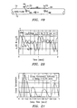
- cross-correlation may be used to determine the time delay ⁇ between two signals y 1 (t),y 2 (t) separated by a known distance ⁇ X, that are indicative of quantities 80 that convect with the flow (e.g., density perturbations, concentration perturbations, temperature perturbations, vortical pressure disturbances, and other quantities).
- the signal y 2 (t) lags behind the signal y 1 (t) by 0.15 seconds.
- a time domain cross-correlation is taken between the two signals y 1 (t),y 2 (t)
- the result is shown in Fig. 20 as a curve 124.
- the highest peak 126 of the curve 124 shows the best fit for the time lag ⁇ between the two signals y 1 (t),y 2 (t) is at 0.15 seconds, which matches the reference time delay, shown in Fig. 21 .
- the vortical pressure disturbances observed at the downstream location are substantially a time lagged version of the vortical pressure disturbances observed at the upstream location.
- the unsteady pressure disturbances P vortical can be masked by the acoustic pressure disturbances P acoustic and the other types of pressure disturbances P other .
- the presence of the acoustic pressure disturbances that propagate both upstream and downstream at the speed of sound in the saturated vapor/liquid mixture (sonic velocity) can prohibit the direct measurement of velocity from cross-correlation of direct vortical pressure measurements.
- the present invention uses temporal and spatial filtering to precondition the pressure signals to effectively filter out the acoustic pressure disturbances P acoustic and other long wavelength (compared to the sensor spacing) pressure disturbances in the pipe 14 at the two sensing regions 76,78 and retain a substantial portion of the vortical pressure disturbances P vortical associated with the vortical flow field 88 and any other short wavelength (compared to the sensor spacing) low frequency pressure disturbances P other .
- the low frequency pressure disturbances P other are small, they will not substantially impair the measurement accuracy of P vortical .
- the P vortical dominated signals from the two regions 76,78 are then cross-correlated to determine the time delay ⁇ between the two sensing locations 76,78. More specifically, at the sensing region 72, the difference between the two pressure sensors 80,82 creates a spatial filter 76 that effectively filters out (or attenuates) acoustic disturbances for which the wavelength ⁇ of the acoustic waves propagating along the flow is long (e.g., ten-to-one) compared to the spacing X 1 between the sensors. Other wavelength to sensor spacing ratios may be used to characterize the filtering, provided the wavelength to sensor spacing ratio is sufficient to satisfy the two-to-one spatial aliasing Nyquist criteria.
- the spatial filter 76 also applies to the second spatial filter 78 comprising the other pair of pressure signals P 3 ,P 4 , axially spaced a distance X 2 apart, which provides the differenced vortical pressure signal P as2 .
- the second technique of determining the convection velocity of the vortical disturbances within the saturated vapor/liquid mixture is by characterizing the convective ridge of the vortical disturbances using an array of unsteady pressure sensors, similar to that shown in U.S. Patent Application Serial No. 09/729,994, filed December 4, 2000 , entitled “Method and Apparatus for Determining the Flow Velocity Within a Pipe", which is incorporated herein by reference.
- the sonar flow metering methodology uses the convection velocity of coherent structure with turbulent pipe flows to determine the volumetric flow rate.
- the convection velocity of these eddies 88 is determined by applying sonar arraying processing techniques to determine the speed at which the eddies convect past an axial array of unsteady pressure measurements distributed along the pipe 14.
- the sonar-based algorithms determine the speed of the eddies by characterizing both the temporal and spatially frequency characteristics of the flow field.
- ⁇ is the temporal frequency in rad/sec
- U convect is the convection velocity.
- K- ⁇ plots are essentially three-dimensional power spectra in which the power of a sound field is decomposed into bins corresponding to specific spatial wave numbers and temporal frequencies.
- the power associated with a pressure field convecting with the flow is distributed in regions, which satisfies the dispersion relationship developed above. This region is termed “the convective ridge” (Beranek, 1992) and the slope of this ridge on a k-w plot indicates the convective velocity of the pressure field. This suggests that the convective velocity of turbulent eddies, and hence flow rate within a pipe, can be determined by constructing a k- ⁇ plot from the output of a phased array of sensor and identifying the slope of the convective ridge.
- Fig. 22 shows an example of a k- ⁇ plot generated from a phased array of pressure sensors.
- the power contours show a well-defined convective ridge.
- a parametric optimization method was used to determine the "best" line representing the slope of the convective ridge 100. For this case, a slope of 4.33 m/s (14.2 ft/sec) was determined.
- the intermediate result of the optimization procedure is displayed in the insert, showing that optimized value is a unique and well-defined optima.
- Fig. 22 illustrates the fundamental principle behind sonar based flow measure, namely that axial arrays of pressure sensors can be used in conjunction with sonar processing techniques to determine the speed at which naturally occurring turbulent eddies convect within a pipe.
- a flowmeter 8 to determine the speed of sound of the mixture provides various specific properties of a saturated vapor/liquid mixture and the velocity of the mixture and further utilizing logic comprising information about the mixture based on the measured parameters.
- the steady state pressure and temperature of the saturated vapor/liquid mixture flowing in a pipe 12 in a power plant 1 ( Fig. 2 ) or other industrial steam process may be measured by any known or contemplated method as represented by 170 from which various fluid properties may be determined from tables or graphs of the known relationships for speed of sound and density for the vapor and liquid phases of the mixture as represented by 171.
- the speed of sound of the saturated vapor/liquid mixture is determined by the flowmeter of the present invention as set forth herein above and represented by 172.
- the quality of the saturated vapor/liquid mixture is determined from the fluid properties of 171 combined with the saturated vapor/liquid mixture speed of sound 172 using the Wood equation (or similar) as set forth herein above and represented by 173.
- the present invention also enables the determination of other properties of the saturated vapor/liquid mixture such as enthalpy and density as set forth by 174 by combining the fluid properties of 171 with the quality of the saturated vapor/liquid mixture from 173.
- the present invention further enables the determination of the velocity of the saturated vapor/liquid mixture by the methods described herein above as represented by 175.
- the total volumetric flow rate of the saturated vapor/liquid mixture is thereby determined as represented by 176 and when combined with the parameters of other properties of the saturated vapor/liquid mixture such as enthalpy and density as set forth by 174 various flux rates of the mixture such as enthalpy and mass flow rates are enabled as represented by 177.
- the length of the array of sensors of the flow meter 10 of Fig. 3 is dependent on the size of the droplets
- the length of the array of the flow meter 70 of Fig. 17 is dependent on the length of the coherence of the vortical eddies. Consequently, one will appreciate that while the flow meters 10,70 of Figs. 3 and 17 , respectively, are shown as separate, distinct flow meters, one will appreciate that the processing units 30,74, respectively, may receive unsteady pressure signals from a common array of sensors 50,72, respectively, provided the size of the liquid droplets are sufficiently small and/or the coherence of the vortical eddies are sufficiently long in duration. Further the processing units 30,74 may comprise the same hardware (or single unit), wherein the unsteady pressure signals are simply processed separately to provide their respective output signals.
- the pressure sensors 15-18 described herein may be any type of pressure sensor, capable of measuring the unsteady (or ac or dynamic) pressures within a pipe 14, such as piezoelectric, optical, capacitive, resistive (e.g., Wheatstone bridge), accelerometers (or geophones), velocity measuring devices, displacement measuring devices, etc. If optical pressure sensors are used, the sensors 15-18 may be Bragg grating based pressure sensors, such as that described in US Patent Application, Serial No. 08/925,598 , entitled “High Sensitivity Fiber Optic Pressure Sensor For Use In Harsh Environments", filed Sept. 8, 1997, now U.S. Patent 6,016,702 , and in US Patent Application, Serial No.
- the sensors 14 may be electrical or optical strain gages attached to or embedded in the outer or inner wall of the pipe which measure pipe wall strain, including microphones, hydrophones, or any other sensor capable of measuring the unsteady pressures within the pipe 14.
- fiber optics as the pressure sensors 14 they may be connected individually or may be multiplexed along one or more optical fibers using wavelength division multiplexing (WDM), time division multiplexing (TDM), or any other optical multiplexing techniques.
- WDM wavelength division multiplexing
- TDM time division multiplexing
- the pressure sensors including electrical strain gages, optical fibers and/or gratings among others as described herein, may be attached to the pipe by adhesive, glue, epoxy, tape or other suitable attachment means to ensure suitable contact between the sensor and the pipe 14.
- the sensors may alternatively be removable or permanently attached via known mechanical techniques such as mechanical fastener, spring loaded, clamped, clam shell arrangement, strapping or other equivalents.
- the strain gages, including optical fibers and/or gratings may be embedded in a composite pipe. If desired, for certain applications, the gratings may be detached from (or strain or acoustically isolated from) the pipe 14 if desired.
- any other strain sensing technique may be used to measure the variations in strain in the pipe, such as highly sensitive piezoelectric, electronic or electric, strain gages attached to or embedded in the pipe 14.
- a piezo-electronic pressure transducer may be used as one or more of the pressure sensors 15-18 and it may measure the unsteady (or dynamic or ac) pressure variations inside the pipe 14 by measuring the pressure levels inside of the pipe.
- the sensors 14 comprise pressure sensors manufactured by PCB Piezotronics.
- one pressure sensor there are integrated circuit piezoelectric voltage mode-type sensors that feature built-in microelectronic amplifiers, and convert the high-impedance charge into a low-impedance voltage output.
- Model 106B manufactured by PCB Piezotronics which is a high sensitivity, acceleration compensated integrated circuit piezoelectric quartz pressure sensor suitable for measuring low pressure acoustic phenomena in hydraulic and pneumatic systems. It has the unique capability to measure small pressure changes of less than 0.001 psi under high static conditions.
- the 106B has a 300 mV/psi sensitivity and a resolution of 91 dB (0.0001 psi).
- the pressure sensors incorporate a built-in MOSFET microelectronic amplifier to convert the high-impedance charge output into a low-impedance voltage signal.
- the sensor is powered from a constant-current source and can operate over long coaxial or ribbon cable without signal degradation.
- the low-impedance voltage signal is not affected by triboelectric cable noise or insulation resistance-degrading contaminants.
- Power to operate integrated circuit piezoelectric sensors generally takes the form of a low-cost, 24 to 27 VDC, 2 to 20 mA constant-current supply.
- a data acquisition system of the present invention may incorporate constant-current power for directly powering integrated circuit piezoelectric sensors.
- piezoelectric pressure sensors are constructed with either compression mode quartz crystals preloaded in a rigid housing, or unconstrained tourmaline crystals. These designs give the sensors microsecond response times and resonant frequencies in the hundreds of kHz, with minimal overshoot or ringing. Small diaphragm diameters ensure spatial resolution of narrow shock waves.
- the output characteristic of piezoelectric pressure sensor systems is that of an AC-coupled system, where repetitive signals decay until there is an equal area above and below the original base line. As magnitude levels of the monitored event fluctuate, the output remains stabilized around the base line with the positive and negative areas of the curve remaining equal.
- each of the pressure sensors 15-18 of the flow meters 10,70 may include a piezoelectric sensor 104-107 that provides a piezoelectric material 110 to measure the unsteady pressures of the fluid/particle mixture 12 as shown in Fig. 24 .
- the piezoelectric material such as the polymer, polarized fluoropolymer, polyvinylidene fluoride (PVDF), measures the strain induced within the process pipe 14 due to unsteady pressure variations within the process mixture 12. Strain within the pipe is transduced to an output voltage or current by the attached piezoelectric sensors 104-107.
- the PVDF material 110 is adhered to the outer surface of a steel strap 112 that extends around and clamps onto the outer surface of the pipe 14.
- the piezoelectric sensing element is typically conformal to allow complete or nearly complete circumferential measurement of induced strain.
- the sensors can be formed from PVDF films, co-polymer films, or flexible PZT sensors, similar to that described in "Piezo Film Sensors technical Manual” provided by Measurement Specialties, Inc., which is incorporated herein by reference. The advantages of this technique are the following:
- While the present invention is capable of measuring liquid droplets suspended in a vapor, one will appreciate that other multi-phase mixtures or flows may be measured using an array of sensors, such as solid particles suspended in a fluid. It is further recognize the effects of dispersion on large droplets of liquid would be similar to large solid particles dispersed in a fluid (e.g., gas or air), and thus similar considerations when measuring the air-to-particle ratio and particle size should be addressed.
- a fluid e.g., gas or air
Landscapes
- Physics & Mathematics (AREA)
- Fluid Mechanics (AREA)
- General Physics & Mathematics (AREA)
- Electromagnetism (AREA)
- Acoustics & Sound (AREA)
- Investigating Or Analyzing Materials By The Use Of Ultrasonic Waves (AREA)
- Measuring Volume Flow (AREA)
Claims (18)
- Vorrichtung zum Messen wenigstens eines Parameters eines Gemisches in einem Rohr, wobei die Vorrichtung Folgendes aufweist:eine räumliche Anordnung von wenigstens zwei Drucksensoren, die an verschiedenen axialen Stellen entlang des Rohrs angeordnet ist und von denen jeder einen schwankenden Druck innerhalb des Rohrs an einer entsprechenden axialen Stelle misst, wobei jeder der Sensoren ein Drucksignal liefert, das den schwankenden Druck innerhalb des Rohrs an der axialen Stelle von einem entsprechenden der Sensoren anzeigt; undeinen Signalprozessor, der auf die Drucksignale anspricht und dazu ausgebildet ist, die Geschwindigkeit des Schalls, der sich durch das Gemisch ausbreitet, das in einem Gas suspendierte Flüssigkeitströpfchen aufweist, als Funktion der Frequenz zu bestimmen, um Dispersionseigenschaften des Gemisches zu charakterisieren und die Dispersionseigenschaften des Gemisches mit einem Dispersionsmodell des Gemisches zu vergleichen und dadurch ein Signal bereitzustellen, das den wenigstens einen Parameter des Gemisches in dem Rohr anzeigt.
- Vorrichtung nach Anspruch 1,
wobei jeder Sensor ein Wirbeldruckfeld misst, das mit dem Gemisch konvektiert, sowie ein Schalldruckfeld misst, das durch das Gemisch konvektiert. - Vorrichtung nach Anspruch 1,
wobei der Signalprozessor in Reaktion auf die Drucksignale ein Signal bereitstellt, das die Geschwindigkeit des sich durch das Gemisch in dem Rohr ausbreitenden Schalls sowie die Geschwindigkeit des Gemisches in dem Rohr anzeigt. - Vorrichtung nach Anspruch 3,
wobei der Signalprozessor eine Logik aufweist, die eine Geschwindigkeit der Schallausbreitung entlang der räumlichen Anordnung sowie die Geschwindigkeit berechnet, mit der sich das Gemisch entlang der räumlichen Anordnung ausbreitet. - Vorrichtung nach Anspruch 1,
die wenigstens drei Sensoren aufweist. - Vorrichtung nach Anspruch 1,
wobei wenigstens einer der Drucksensoren Belastung an dem Rohr misst. - Vorrichtung nach Anspruch 1,
wobei wenigstens ein Sensor ein erstes Filter, das ein Wirbeldruckfeld an einer ersten axialen Stelle entlang des Rohrs misst und ein erstes Drucksignal liefert, das das Wirbeldruckfeld anzeigt; und wenigstens ein zweiter Sensor ein zweites Filter bereitstellt, das das Wirbeldruckfeld an einer zweiten axialen Stelle entlang des Rohrs misst und ein zweites Drucksignal liefert, das das Wirbeldruckfeld anzeigt, wobei die erste und die zweite Stelle axial voneinander beabstandet sind. - Vorrichtung nach Anspruch 7,
wobei der Signalprozessor in Reaktion auf das erste und das zweite Drucksignal ein Geschwindigkeitssignal liefert, das eine Geschwindigkeit des sich in dem Rohr bewegenden Wirbeldruckfelds anzeigt. - Vorrichtung nach Anspruch 7,
wobei das erste und das zweite Filter Wellenlängen heraus filtern, die einem Schalldruckfeld zugeordnet ist, und Wellenlängen hindurch lassen, die dem Wirbeldruckfeld zugeordnet sind. - Vorrichtung nach Anspruch 9,
wobei das erste Filter ein erstes Raumfilter aufweist, das wenigstens einen ersten und einen zweiten Drucksensor für schwankenden Druck aufweist, die in einem vorbestimmten ersten Abstand voneinander angeordnet sind; und das zweite Filter ein zweites Raumfilter aufweist, das wenigstens einen dritten und einen vierten Drucksensor für schwankenden Druck aufweist, die in einem vorbestimmten zweiten Abstand voneinander angeordnet sind. - Vorrichtung nach Anspruch 1,
wobei der wenigstens eine Parameter des Gemisches wenigstens eines beinhaltet von einer Gas-/Flüssigkeits-Zusammensetzung, der Nässe oder Dampfqualität (volumetrischer Phasenanteil), dem Volumenstrom, der Größe der Flüssigkeitspartikel, der Masseströmung, der Enthalpie, der Dichte, der Geschwindigkeit des Gemisches in dem Rohr sowie der Geschwindigkeit des Schalls, der sich durch das Gemisch in dem Rohr ausbreitet. - Verfahren zum Bestimmen wenigstens eines Parameters eines Gemisches in einem Rohr, wobei das Verfahren folgende Schritte aufweist:Messen von schwankenden Drücken innerhalb des Rohrs von wenigstens zwei verschiedenen axialen Messstellen entlang des Rohrs zum Liefern eines Drucksignals, das den schwankenden Druck innerhalb des Rohrs an jeder der wenigstens zwei vorgegebenen axialen Messstellen anzeigt;gekennzeichnet durchBerechnen des wenigstens einen Parameters des Gemisches in dem Rohr unter Verwendung des an den axialen Messstellen gemessenen schwankenden Drucks durch Bestimmen der Geschwindigkeit des Schalls, der sich durch das Gemisch ausbreitet, das in einem Gas suspendierte Flüssigkeitströpfchen aufweist, als Funktion der Frequenz, um Dispersionseigenschaften des Gemisches zu charakterisieren, sowie durch Vergleichen der Dispersionseigenschaften des Gemisches mit einem Dispersionsmodell des Gemisches.
- Verfahren nach Anspruch 12,
wobei das Messen von variierenden Drücken beinhaltet:Messen eines Wirbeldruckfelds an einer ersten Stelle entlang des Rohrs und Bereitstellen eines ersten Wirbeldrucksignals, das das Wirbeldruckfeld anzeigt; und Messen des Wirbeldruckfelds an einer zweiten Stelle entlang des Rohrs und Bereitstellen eines zweiten Wirbeldrucksignals, das das Wirbeldruckfeld anzeigt, wobei die erste und die zweite Stelle axial voneinander beabstandet sind. - Verfahren nach Anspruch 13,
wobei das Berechnen des wenigstens einen Parameters das erste und das zweite Wirbeldrucksignal zum Berechnen der Geschwindigkeit des Gemisches in dem Rohr verwendet. - Verfahren nach Anspruch 12,
wobei der Parameter wenigstens eines beinhaltet von einer Gas-/Flüssigkeits-Zusammensetzung, der Nässe oder Dampfqualität (volumetrischer Phasenanteil), dem Volumenstrom, der Größe der Flüssigkeitspartikel, der Masseströmung, der Enthalpie, der Dichte, der Geschwindigkeit des Gemisches in dem Rohr sowie der Geschwindigkeit des Schalls, der sich durch das Gemisch in dem Rohr ausbreitet. - Verfahren nach Anspruch 12,
wobei jeder Sensor ein Wirbeldruckfeld misst, das mit dem Gemisch konvektiert, sowie ein Schalldruckfeld misst, das durch das Gemisch konvektiert. - Verfahren nach Anspruch 12,
wobei das Berechnen des wenigstens einen Parameters das Bereitstellen eines Signals beinhaltet, das die Geschwindigkeit des sich durch das Gemisch in dem Rohr ausbreitenden Schalls sowie die Geschwindigkeit des Gemisches in Reaktion auf die schwankenden Drücke anzeigt. - Verfahren nach Anspruch 12,
wobei das Messen von schwankendem Druck von wenigstens zwei verschiedenen axialen Stellen das Messen von schwankendem Druck von wenigstens drei verschiedenen axialen Stellen beinhaltet.
Applications Claiming Priority (11)
| Application Number | Priority Date | Filing Date | Title |
|---|---|---|---|
| US349716 | 1989-05-10 | ||
| US35978502P | 2002-02-26 | 2002-02-26 | |
| US359785P | 2002-02-26 | ||
| US37584702P | 2002-04-24 | 2002-04-24 | |
| US375847P | 2002-04-24 | ||
| US42543602P | 2002-11-12 | 2002-11-12 | |
| US425436P | 2002-11-12 | ||
| US42672402P | 2002-11-15 | 2002-11-15 | |
| US426724P | 2002-11-15 | ||
| US10/349,716 US7359803B2 (en) | 2002-01-23 | 2003-01-23 | Apparatus and method for measuring parameters of a mixture having solid particles suspended in a fluid flowing in a pipe |
| PCT/US2003/006178 WO2003073047A1 (en) | 2002-02-26 | 2003-02-26 | Apparatus and method for measuring parameters of a mixture having liquid droplets suspended in a vapor flowing in a pipe |
Publications (2)
| Publication Number | Publication Date |
|---|---|
| EP1481223A1 EP1481223A1 (de) | 2004-12-01 |
| EP1481223B1 true EP1481223B1 (de) | 2016-01-06 |
Family
ID=27767953
Family Applications (1)
| Application Number | Title | Priority Date | Filing Date |
|---|---|---|---|
| EP03713789.0A Expired - Lifetime EP1481223B1 (de) | 2002-02-26 | 2003-02-26 | Gerät und verfahren zum messen von parametern einer in einer leitung strömenden mischung, die in einem dampf suspendierte flüssigkeitströpfchen enthält |
Country Status (6)
| Country | Link |
|---|---|
| US (1) | US7359803B2 (de) |
| EP (1) | EP1481223B1 (de) |
| CN (1) | CN100529684C (de) |
| AU (1) | AU2003217823A1 (de) |
| CA (1) | CA2480460C (de) |
| WO (1) | WO2003073047A1 (de) |
Families Citing this family (106)
| Publication number | Priority date | Publication date | Assignee | Title |
|---|---|---|---|---|
| US7275421B2 (en) * | 2002-01-23 | 2007-10-02 | Cidra Corporation | Apparatus and method for measuring parameters of a mixture having solid particles suspended in a fluid flowing in a pipe |
| US7328624B2 (en) * | 2002-01-23 | 2008-02-12 | Cidra Corporation | Probe for measuring parameters of a flowing fluid and/or multiphase mixture |
| US7032432B2 (en) * | 2002-01-23 | 2006-04-25 | Cidra Corporation | Apparatus and method for measuring parameters of a mixture having liquid droplets suspended in a vapor flowing in a pipe |
| US7474966B2 (en) * | 2002-01-23 | 2009-01-06 | Expro Meters. Inc | Apparatus having an array of piezoelectric film sensors for measuring parameters of a process flow within a pipe |
| US7359803B2 (en) | 2002-01-23 | 2008-04-15 | Cidra Corporation | Apparatus and method for measuring parameters of a mixture having solid particles suspended in a fluid flowing in a pipe |
| US7181955B2 (en) * | 2002-08-08 | 2007-02-27 | Weatherford/Lamb, Inc. | Apparatus and method for measuring multi-Phase flows in pulp and paper industry applications |
| US7400985B2 (en) * | 2002-11-12 | 2008-07-15 | Cidra Corporation | Apparatus having an array of clamp on piezoelectric film sensors for measuring parameters of a process flow within a pipe |
| US7165464B2 (en) * | 2002-11-15 | 2007-01-23 | Cidra Corporation | Apparatus and method for providing a flow measurement compensated for entrained gas |
| AU2003295992A1 (en) * | 2002-11-22 | 2004-06-18 | Cidra Corporation | Method for calibrating a flow meter having an array of sensors |
| US7096719B2 (en) | 2003-01-13 | 2006-08-29 | Cidra Corporation | Apparatus for measuring parameters of a flowing multiphase mixture |
| WO2004063675A2 (en) * | 2003-01-13 | 2004-07-29 | Cidra Corporation | Apparatus and method using an array of ultrasonic sensors for determining the velocity of a fluid within a pipe |
| US20060048583A1 (en) * | 2004-08-16 | 2006-03-09 | Gysling Daniel L | Total gas meter using speed of sound and velocity measurements |
| DE602004017571D1 (de) * | 2003-01-21 | 2008-12-18 | Expro Meters Inc | Vorrichtung und verfahren zur messung der gasvolumenfraktion eines in einem rohr strömenden fluids |
| ATE549603T1 (de) | 2003-01-21 | 2012-03-15 | Cidra Corporate Services Inc | Messung eingeschlossener und aufgelöster gase in prozessflussleitungen |
| WO2004065912A2 (en) * | 2003-01-21 | 2004-08-05 | Cidra Corporation | Apparatus and method for measuring unsteady pressures within a large diameter pipe |
| US7343818B2 (en) * | 2003-01-21 | 2008-03-18 | Cidra Corporation | Apparatus and method of measuring gas volume fraction of a fluid flowing within a pipe |
| WO2004079306A1 (en) | 2003-03-04 | 2004-09-16 | Cidra Corporation | An apparatus having a multi-band sensor assembly for measuring a parameter of a fluid flow flowing within a pipe |
| WO2004109239A2 (en) | 2003-06-05 | 2004-12-16 | Cidra Corporation | Apparatus for measuring velocity and flow rate of a fluid having a non-negligible axial mach number using an array of sensors |
| WO2005001394A2 (en) * | 2003-06-06 | 2005-01-06 | Cidra Corporation | A portable flow measurement apparatus having an array of sensors |
| US7197938B2 (en) * | 2003-06-24 | 2007-04-03 | Cidra Corporation | Contact-based transducers for characterizing unsteady pressures in pipes |
| EP1644705B1 (de) * | 2003-06-24 | 2016-10-12 | Cidra Corporate Services, Inc. | System und verfahren zum betreiben eines flussprozesses |
| US7245385B2 (en) * | 2003-06-24 | 2007-07-17 | Cidra Corporation | Characterizing unsteady pressures in pipes using optical measurement devices |
| US7150202B2 (en) * | 2003-07-08 | 2006-12-19 | Cidra Corporation | Method and apparatus for measuring characteristics of core-annular flow |
| US7134320B2 (en) * | 2003-07-15 | 2006-11-14 | Cidra Corporation | Apparatus and method for providing a density measurement augmented for entrained gas |
| CA2532468C (en) * | 2003-07-15 | 2013-04-23 | Cidra Corporation | A dual function flow measurement apparatus having an array of sensors |
| CA2532577C (en) * | 2003-07-15 | 2013-01-08 | Cidra Corporation | A configurable multi-function flow measurement apparatus having an array of sensors |
| CA2537897C (en) * | 2003-08-01 | 2014-06-10 | Cidra Corporation | Method and apparatus for measuring a parameter of a high temperature fluid flowing within a pipe using an array of piezoelectric based flow sensors |
| US7882750B2 (en) * | 2003-08-01 | 2011-02-08 | Cidra Corporate Services, Inc. | Method and apparatus for measuring parameters of a fluid flowing within a pipe using a configurable array of sensors |
| WO2005012843A2 (en) | 2003-08-01 | 2005-02-10 | Cidra Corporation | Method and apparatus for measuring parameters of a fluid flowing within a pipe using a configurable array of sensors |
| WO2005015135A2 (en) * | 2003-08-08 | 2005-02-17 | Cidra Corporation | Piezocable based sensor for measuring unsteady pressures inside a pipe |
| US7110893B2 (en) * | 2003-10-09 | 2006-09-19 | Cidra Corporation | Method and apparatus for measuring a parameter of a fluid flowing within a pipe using an array of sensors |
| US7237440B2 (en) * | 2003-10-10 | 2007-07-03 | Cidra Corporation | Flow measurement apparatus having strain-based sensors and ultrasonic sensors |
| CA2445426A1 (en) * | 2003-10-17 | 2005-04-17 | Alberta Research Council Inc. | A method for characterizing a dispersion using transformation techniques |
| US7171315B2 (en) * | 2003-11-25 | 2007-01-30 | Cidra Corporation | Method and apparatus for measuring a parameter of a fluid flowing within a pipe using sub-array processing |
| WO2005059479A1 (en) | 2003-12-11 | 2005-06-30 | Cidra Corporation | Method and apparatus for determining a quality metric of a measurement of a fluid parameter |
| US7330797B2 (en) * | 2004-03-10 | 2008-02-12 | Cidra Corporation | Apparatus and method for measuring settlement of solids in a multiphase flow |
| WO2005088262A2 (en) | 2004-03-10 | 2005-09-22 | Cidra Corporation | Method and apparatus for measuring parameters of a stratified flow |
| US7367239B2 (en) | 2004-03-23 | 2008-05-06 | Cidra Corporation | Piezocable based sensor for measuring unsteady pressures inside a pipe |
| US7426852B1 (en) | 2004-04-26 | 2008-09-23 | Expro Meters, Inc. | Submersible meter for measuring a parameter of gas hold-up of a fluid |
| WO2005116637A2 (en) * | 2004-05-17 | 2005-12-08 | Cidra Corporation | Apparatus and method for measuring the composition of a mixture |
| WO2006112878A2 (en) | 2004-09-16 | 2006-10-26 | Cidra Corporation | Apparatus and method for providing a fluid cut measurement of a multi-liquid mixture compensated for entrained gas |
| US7389687B2 (en) * | 2004-11-05 | 2008-06-24 | Cidra Corporation | System for measuring a parameter of an aerated multi-phase mixture flowing in a pipe |
| US7561203B2 (en) * | 2005-01-10 | 2009-07-14 | Nokia Corporation | User input device |
| WO2006099342A1 (en) | 2005-03-10 | 2006-09-21 | Cidra Corporation | An industrial flow meter having an accessible digital interface |
| US7962293B2 (en) | 2005-03-10 | 2011-06-14 | Expro Meters, Inc. | Apparatus and method for providing a stratification metric of a multiphase fluid flowing within a pipe |
| WO2010120258A2 (en) * | 2005-03-17 | 2010-10-21 | Cidra Corporation | An apparatus and method of processing data to improve the performance of a flow monitoring system |
| US7657392B2 (en) * | 2005-05-16 | 2010-02-02 | Cidra Corporate Services, Inc. | Method and apparatus for detecting and characterizing particles in a multiphase fluid |
| MX2007014705A (es) * | 2005-05-27 | 2008-02-15 | Cidra Corp | Un aparato y metodo para medir un parametro de un flujo de fases multiples. |
| US7526966B2 (en) * | 2005-05-27 | 2009-05-05 | Expro Meters, Inc. | Apparatus and method for measuring a parameter of a multiphase flow |
| ATE482380T1 (de) * | 2005-07-07 | 2010-10-15 | Expro Meters Inc | Mehrphasiges durchflussmessungssystem mit flüssigkeitsabscheider |
| US7603916B2 (en) * | 2005-07-07 | 2009-10-20 | Expro Meters, Inc. | Wet gas metering using a differential pressure and a sonar based flow meter |
| EP1899686B1 (de) * | 2005-07-07 | 2011-09-28 | CiDra Corporation | Feuchtgasmessung unter verwendung eines differentialdruckbasierten durchflussmeters mit einem sonarbasierten durchflussmeter |
| WO2007009097A1 (en) | 2005-07-13 | 2007-01-18 | Cidra Corporation | Method and apparatus for measuring parameters of a fluid flow using an array of sensors |
| US7379792B2 (en) * | 2005-09-29 | 2008-05-27 | Rosemount Inc. | Pressure transmitter with acoustic pressure sensor |
| US7454981B2 (en) * | 2006-05-16 | 2008-11-25 | Expro Meters. Inc. | Apparatus and method for determining a parameter in a wet gas flow |
| US7624650B2 (en) | 2006-07-27 | 2009-12-01 | Expro Meters, Inc. | Apparatus and method for attenuating acoustic waves propagating within a pipe wall |
| EP2069724A2 (de) | 2006-08-01 | 2009-06-17 | CiDra Corporation | Verfahren zur überwachung einer fliessenden flüssigkeit |
| US7385503B1 (en) * | 2006-08-03 | 2008-06-10 | Rosemount, Inc. | Self powered son device network |
| US7624651B2 (en) * | 2006-10-30 | 2009-12-01 | Expro Meters, Inc. | Apparatus and method for attenuating acoustic waves in pipe walls for clamp-on ultrasonic flow meter |
| US7673526B2 (en) * | 2006-11-01 | 2010-03-09 | Expro Meters, Inc. | Apparatus and method of lensing an ultrasonic beam for an ultrasonic flow meter |
| NO345532B1 (no) | 2006-11-09 | 2021-03-29 | Expro Meters Inc | Apparat og fremgangsmåte for måling av en fluidstrømparameter innenfor en intern passasje i et langstrakt legme |
| US8499620B2 (en) * | 2007-03-30 | 2013-08-06 | Kawasaki Jukogyo Kabushiki Kaisha | Gum substance monitoring apparatus, gum substance detecting method, and gas turbine system |
| WO2009002394A1 (en) * | 2007-06-21 | 2008-12-31 | Avistar, Inc. | Method and apparatus for controlling relative coal flow in pipes from a pulverizer |
| US7810400B2 (en) | 2007-07-24 | 2010-10-12 | Cidra Corporate Services Inc. | Velocity based method for determining air-fuel ratio of a fluid flow |
| US8862411B2 (en) * | 2007-08-24 | 2014-10-14 | Expro Meters, Inc. | Velocity and impingement method for determining parameters of a particle/fluid flow |
| DE102007062908A1 (de) | 2007-12-21 | 2009-06-25 | Endress + Hauser Flowtec Ag | Verfahren und System zur Bestimmung mindestens einer Prozessgröße eines strömenden Mediums |
| US8061186B2 (en) | 2008-03-26 | 2011-11-22 | Expro Meters, Inc. | System and method for providing a compositional measurement of a mixture having entrained gas |
| US20100251943A1 (en) * | 2009-04-01 | 2010-10-07 | General Electric Company | Slag zone mapping |
| MX2011011686A (es) * | 2009-05-04 | 2012-04-30 | Agar Corp Ltd | Procedimiento y aparato de medición de fluido de multi-fase. |
| GB2517614B (en) * | 2009-05-27 | 2015-06-24 | Silixa Ltd | Fibre arrangement for distributed acoustic sensing |
| CN102072407A (zh) * | 2009-11-23 | 2011-05-25 | 中国科学院生态环境研究中心 | 结合漏失记录仪的独立计量分区漏失检测方法 |
| CN101799464B (zh) * | 2010-04-14 | 2013-11-06 | 三一电气有限责任公司 | 一种空气密度检测装置和空气密度检测方法 |
| US8746158B2 (en) | 2011-09-09 | 2014-06-10 | Cnh Industrial Canada, Ltd. | System and method for measuring product flow to an agricultural implement |
| US8869718B2 (en) | 2011-09-09 | 2014-10-28 | Cnh Industrial Canada, Ltd. | System and method for controlling product flow to an agricultural implement |
| NL1039764C2 (en) * | 2012-08-17 | 2014-02-18 | J O A Technology Beheer B V | A method of, a control system, a device, a sensor and a computer program product for controlling transport of fibrous material in a transport line of a pneumatic conveying system. |
| GB2505905B (en) * | 2012-09-13 | 2018-02-14 | Spirax-Sarco Ltd | Method and apparatus for determining the phase compositions of a multiphase fluid flow |
| CA2909902C (en) * | 2013-04-19 | 2018-03-13 | Gutermann Ag | Method for evaluating acoustic sensor data in a fluid carrying network and evaluation unit |
| US9410422B2 (en) | 2013-09-13 | 2016-08-09 | Chevron U.S.A. Inc. | Alternative gauging system for production well testing and related methods |
| CN103953098B (zh) * | 2014-04-22 | 2016-08-24 | 中国科学院生态环境研究中心 | 管网漏失监测方法 |
| EP3974781A1 (de) * | 2016-07-18 | 2022-03-30 | Vaughn Realty Ventures LLC | Wassermesssystem |
| US12222231B2 (en) | 2016-07-18 | 2025-02-11 | Vaughn Realty Ventures LLC | Water metering system |
| US11821770B2 (en) | 2016-07-18 | 2023-11-21 | Vaughn Realty Ventures LLC | Water metering system |
| AT520557B1 (de) * | 2018-01-24 | 2019-05-15 | Anton Paar Gmbh | Verfahren zur Ermittlung eines korrigierten Werts für die viskositätsabhängige Schallgeschwindigkeit in einem zu untersuchenden Fluid |
| US11547998B2 (en) | 2018-02-12 | 2023-01-10 | Hewlett-Packard Development Company, L.P. | Devices to measure flow rates with movable elements |
| WO2019156687A1 (en) | 2018-02-12 | 2019-08-15 | Hewlett-Packard Development Company, L.P. | Microfluidic flow sensor |
| CN109470289B (zh) * | 2018-09-18 | 2021-11-05 | 中国电力科学研究院有限公司 | 一种识别计量设备用能流量值反向事件的方法和系统 |
| US11231311B2 (en) | 2019-05-31 | 2022-01-25 | Perceptive Sensor Technologies Llc | Non-linear ultrasound method and apparatus for quantitative detection of materials |
| CA3144795A1 (en) | 2019-07-10 | 2021-01-14 | Expro Meters, Inc. | Apparatus and method for measuring fluid flow parameters |
| JP2022546139A (ja) * | 2019-09-02 | 2022-11-02 | 株式会社マリ | 酸素および非侵襲的換気療法監視装置 |
| CN111829601B (zh) * | 2020-07-21 | 2022-03-18 | 中国人民解放军国防科技大学 | 流体的多状态参数同步测量方法及装置、电子设备和介质 |
| WO2022120074A1 (en) | 2020-12-02 | 2022-06-09 | Perceptive Sensor Technologies Llc | Variable angle transducer interface block |
| WO2022120258A1 (en) | 2020-12-04 | 2022-06-09 | Perceptive Sensor Technologies, Inc. | Multi-bounce acoustic signal material detection |
| US11788904B2 (en) | 2020-12-04 | 2023-10-17 | Perceptive Sensor Technologies, Inc. | Acoustic temperature measurement in layered environments |
| CA3205706A1 (en) * | 2020-12-04 | 2022-06-09 | Lazar Bivolarsky | Multi-path acoustic signal improvement for material detection |
| CA3203819A1 (en) | 2020-12-30 | 2022-07-07 | Lazar Bivolarsky | Evaluation of fluid quality with signals |
| CN113358526B (zh) * | 2021-04-26 | 2022-07-12 | 中国矿业大学 | 基于能量耗散理论的水合物浆液流动压降预测方法和系统 |
| US12298165B2 (en) | 2021-08-26 | 2025-05-13 | Corvera, LLC | Methods and apparatus for determining the speed of sound within a piping network |
| WO2023114382A1 (en) * | 2021-12-17 | 2023-06-22 | Corvera Llc | Apparatus and method for measuring a parameter of a process fluid |
| CN114323176A (zh) * | 2021-12-31 | 2022-04-12 | 江苏微浪电子科技有限公司 | 大管道变组分气体质量流量测量方法 |
| CN114488007B (zh) * | 2022-01-12 | 2025-05-30 | 同济大学 | 一种浅海非均匀媒质中的无人潜航器定位方法和系统 |
| WO2023154514A1 (en) | 2022-02-11 | 2023-08-17 | Perceptive Sensor Technologies, Inc. | Acoustic signal detection of material composition in static and dynamic conditions |
| US12123889B2 (en) * | 2022-04-07 | 2024-10-22 | Corvera, LLC | Apparatus and method for measuring a parameter of a process fluid |
| US12130301B2 (en) | 2022-04-24 | 2024-10-29 | Corvera, LLC | Method to determine characteristics of a bubbly mixture using a Coriolis meter utilizing a measure of the drive gain |
| US11940420B2 (en) | 2022-07-19 | 2024-03-26 | Perceptive Sensor Technologies, Inc. | Acoustic signal material identification with nanotube couplant |
| CN117030842A (zh) * | 2023-07-21 | 2023-11-10 | 沈阳工业大学 | 一种基于声学技术的管道内水蒸气干度测量方法及系统 |
| CN120971563B (zh) * | 2025-10-22 | 2026-03-06 | 克拉玛依市富城油砂矿资源开发有限责任公司 | 一种蒸汽干度测量装置 |
Family Cites Families (75)
| Publication number | Priority date | Publication date | Assignee | Title |
|---|---|---|---|---|
| US3751979A (en) * | 1971-11-17 | 1973-08-14 | Raytheon Co | Speed measurement system |
| US3885432A (en) * | 1972-03-06 | 1975-05-27 | Fischer & Porter Co | Vortex-type mass flowmeters |
| US3781895A (en) | 1972-11-22 | 1973-12-25 | Raytheon Co | Combined pitot tube and antenna |
| US3851521A (en) | 1973-01-19 | 1974-12-03 | M & J Valve Co | System and method for locating breaks in liquid pipelines |
| US3952578A (en) | 1974-10-07 | 1976-04-27 | The United States Of America As Represented By The Secretary Of The Department Of Health, Education And Welfare | Scanning ultrasonic spectrograph for fluid analysis |
| US4080837A (en) | 1976-12-03 | 1978-03-28 | Continental Oil Company | Sonic measurement of flow rate and water content of oil-water streams |
| US4320659A (en) | 1978-02-27 | 1982-03-23 | Panametrics, Inc. | Ultrasonic system for measuring fluid impedance or liquid level |
| US4520320A (en) | 1981-09-10 | 1985-05-28 | The United States Of America As Represented By The Secretary Of Commerce | Synchronous phase marker and amplitude detector |
| US4445389A (en) | 1981-09-10 | 1984-05-01 | The United States Of America As Represented By The Secretary Of Commerce | Long wavelength acoustic flowmeter |
| GB2135446B (en) * | 1983-02-11 | 1986-05-08 | Itt Ind Ltd | Fluid flow measurement |
| US4677305A (en) | 1985-06-28 | 1987-06-30 | Simmonds Precision Products, Inc. | Opto-acoustic fuel quantity gauging system |
| US4717159A (en) | 1986-06-06 | 1988-01-05 | Dieterich Standard Corp. | Method and apparatus for seating and sealing a pitot tube type flow meter in a pipe |
| FR2614995B1 (fr) | 1987-05-06 | 1989-07-28 | Schlumberger Prospection | Procede de filtrage en vitesse de signaux sismiques et installation pour sa mise en oeuvre |
| GB2210169A (en) | 1987-09-21 | 1989-06-01 | British Gas Plc | Apparatus for monitoring or measuring differential fluid presure |
| NO166379C (no) | 1987-12-18 | 1991-07-10 | Sensorteknikk As | Fremgangsmaate for registrering av flerfase stroemninger gjennom et transportsystem. |
| US4896540A (en) | 1988-04-08 | 1990-01-30 | Parthasarathy Shakkottai | Aeroacoustic flowmeter |
| US5363342A (en) | 1988-04-28 | 1994-11-08 | Litton Systems, Inc. | High performance extended fiber optic hydrophone |
| US4932262A (en) | 1989-06-26 | 1990-06-12 | General Motors Corporation | Miniature fiber optic pressure sensor |
| GB8918068D0 (en) | 1989-08-08 | 1989-09-20 | Front Engineering Ltd | An apparatus for determining the time taken for sound to cross a body of fluid in an enclosure |
| US5040415A (en) | 1990-06-15 | 1991-08-20 | Rockwell International Corporation | Nonintrusive flow sensing system |
| GB2280267B (en) | 1991-03-21 | 1995-05-24 | Halliburton Co | Device for sensing fluid behaviour |
| US5218197A (en) | 1991-05-20 | 1993-06-08 | The United States Of America As Represented By The Secretary Of The Navy | Method and apparatus for the non-invasive measurement of pressure inside pipes using a fiber optic interferometer sensor |
| US6781895B1 (en) * | 1991-12-19 | 2004-08-24 | Kabushiki Kaisha Toshiba | Non-volatile semiconductor memory device and memory system using the same |
| NO174643C (no) | 1992-01-13 | 1994-06-08 | Jon Steinar Gudmundsson | Apparat og framgangsmåte for bestemmelse av strömningshastighet og gass/væske-forhold i flerefase-strömmer |
| US5289726A (en) * | 1992-09-22 | 1994-03-01 | National Science Council | Ring type vortex flowmeter and method for measuring flow speed and flow rate using said ring type vortex flowmeter |
| US5398542A (en) * | 1992-10-16 | 1995-03-21 | Nkk Corporation | Method for determining direction of travel of a wave front and apparatus therefor |
| DE4306119A1 (de) | 1993-03-01 | 1994-09-08 | Pechhold Wolfgang Prof Dr | Mechanisches Breitbandspektrometer |
| JP3237968B2 (ja) * | 1993-08-18 | 2001-12-10 | 富士通株式会社 | 半導体素子モジュール |
| FI94909C (fi) | 1994-04-19 | 1995-11-10 | Valtion Teknillinen | Akustinen virtausmittausmenetelmä ja sitä soveltava laite |
| FR2720498B1 (fr) | 1994-05-27 | 1996-08-09 | Schlumberger Services Petrol | Débitmètre multiphasique. |
| US5741980A (en) | 1994-11-02 | 1998-04-21 | Foster-Miller, Inc. | Flow analysis system and method |
| US5524475A (en) * | 1994-11-10 | 1996-06-11 | Atlantic Richfield Company | Measuring vibration of a fluid stream to determine gas fraction |
| FR2740215B1 (fr) | 1995-10-19 | 1997-11-21 | Inst Francais Du Petrole | Methode et dispositif pour mesurer un parametre d'un fluide de densite variable |
| US5708211A (en) | 1996-05-28 | 1998-01-13 | Ohio University | Flow regime determination and flow measurement in multiphase flow pipelines |
| US5835884A (en) | 1996-10-04 | 1998-11-10 | Brown; Alvin E. | Method of determining a characteristic of a fluid |
| US6601005B1 (en) * | 1996-11-07 | 2003-07-29 | Rosemount Inc. | Process device diagnostics using process variable sensor signal |
| US5845033A (en) | 1996-11-07 | 1998-12-01 | The Babcock & Wilcox Company | Fiber optic sensing system for monitoring restrictions in hydrocarbon production systems |
| US6170338B1 (en) * | 1997-03-27 | 2001-01-09 | Rosemont Inc. | Vortex flowmeter with signal processing |
| DE19722274A1 (de) * | 1997-05-28 | 1998-12-03 | Degussa | Verfahren zur Messung von Dichte und Massenstrom |
| US5948959A (en) | 1997-05-29 | 1999-09-07 | The United States Of America As Represented By The Secretary Of The Navy | Calibration of the normal pressure transfer function of a compliant fluid-filled cylinder |
| DE19728612C2 (de) * | 1997-07-04 | 2001-11-29 | Promecon Prozess & Messtechnik | Verfahren zur Bestimmung der in einer Zweiphasenströmung mit gasförmigem Trägermedium enthaltenen Menge festen und/oder flüssigen Materials |
| US6138512A (en) | 1997-07-30 | 2000-10-31 | Iowa State University Research Foundation, Inc. | Method and apparatus for determining source location of energy carried in the form of propagating waves through a conducting medium |
| US6016702A (en) | 1997-09-08 | 2000-01-25 | Cidra Corporation | High sensitivity fiber optic pressure sensor for use in harsh environments |
| US6442996B1 (en) | 1998-01-16 | 2002-09-03 | Lattice Intellectual Property Limited | Method and apparatus for measuring the calorific value of a gas |
| RU2001102591A (ru) | 1998-06-26 | 2003-03-10 | Сидрэ Копэрейшн (Us) | Устройство и способ измерения нестабильного давления внутри трубы |
| EP1090274B1 (de) | 1998-06-26 | 2017-03-15 | Weatherford Technology Holdings, LLC | Flüssigkeitsparametermessung unter verwendung von akustischem druck |
| US6354147B1 (en) * | 1998-06-26 | 2002-03-12 | Cidra Corporation | Fluid parameter measurement in pipes using acoustic pressures |
| US6450037B1 (en) | 1998-06-26 | 2002-09-17 | Cidra Corporation | Non-intrusive fiber optic pressure sensor for measuring unsteady pressures within a pipe |
| US6837332B1 (en) * | 1999-03-22 | 2005-01-04 | Halliburton Energy Services, Inc. | Method and apparatus for cancellation of unwanted signals in MWD acoustic tools |
| US6233374B1 (en) | 1999-06-04 | 2001-05-15 | Cidra Corporation | Mandrel-wound fiber optic pressure sensor |
| US6435030B1 (en) | 1999-06-25 | 2002-08-20 | Weatherford/Lamb, Inc. | Measurement of propagating acoustic waves in compliant pipes |
| US6463813B1 (en) | 1999-06-25 | 2002-10-15 | Weatherford/Lamb, Inc. | Displacement based pressure sensor measuring unsteady pressure in a pipe |
| US6536291B1 (en) | 1999-07-02 | 2003-03-25 | Weatherford/Lamb, Inc. | Optical flow rate measurement using unsteady pressures |
| US6691584B2 (en) | 1999-07-02 | 2004-02-17 | Weatherford/Lamb, Inc. | Flow rate measurement using unsteady pressures |
| AU776582B2 (en) | 1999-07-02 | 2004-09-16 | Weatherford Technology Holdings, Llc | Flow rate measurement using unsteady pressures |
| US6449563B1 (en) * | 1999-10-12 | 2002-09-10 | Dispersion Technology, Inc | Method and device for determining particle size distribution and zeta potential in concentrated dispersions |
| US6813962B2 (en) | 2000-03-07 | 2004-11-09 | Weatherford/Lamb, Inc. | Distributed sound speed measurements for multiphase flow measurement |
| US6601458B1 (en) | 2000-03-07 | 2003-08-05 | Weatherford/Lamb, Inc. | Distributed sound speed measurements for multiphase flow measurement |
| US6773603B2 (en) * | 2000-03-13 | 2004-08-10 | Intellectual Capital Enterprises, Inc. | Chemical removal and suspended solids separation pre-treatment system |
| US6378357B1 (en) | 2000-03-14 | 2002-04-30 | Halliburton Energy Services, Inc. | Method of fluid rheology characterization and apparatus therefor |
| US6349599B1 (en) | 2000-05-02 | 2002-02-26 | Panametrics, Inc. | Layered ultrasonic coupler |
| SE516979C2 (sv) | 2000-07-14 | 2002-03-26 | Abb Ab | Aktiv akustisk spektroskopi |
| US6558036B2 (en) | 2000-11-29 | 2003-05-06 | Weatherford/Lamb, Inc. | Non-intrusive temperature sensor for measuring internal temperature of fluids within pipes |
| US6443226B1 (en) | 2000-11-29 | 2002-09-03 | Weatherford/Lamb, Inc. | Apparatus for protecting sensors within a well environment |
| US6782150B2 (en) | 2000-11-29 | 2004-08-24 | Weatherford/Lamb, Inc. | Apparatus for sensing fluid in a pipe |
| US6550342B2 (en) | 2000-11-29 | 2003-04-22 | Weatherford/Lamb, Inc. | Circumferential strain attenuator |
| US6898541B2 (en) | 2000-12-04 | 2005-05-24 | Weatherford/Lamb, Inc. | Method and apparatus for determining component flow rates for a multiphase flow |
| US6587798B2 (en) * | 2000-12-04 | 2003-07-01 | Weatherford/Lamb, Inc. | Method and system for determining the speed of sound in a fluid within a conduit |
| US6609069B2 (en) | 2000-12-04 | 2003-08-19 | Weatherford/Lamb, Inc. | Method and apparatus for determining the flow velocity of a fluid within a pipe |
| US6698297B2 (en) | 2002-06-28 | 2004-03-02 | Weatherford/Lamb, Inc. | Venturi augmented flow meter |
| US7059172B2 (en) | 2001-11-07 | 2006-06-13 | Weatherford/Lamb, Inc. | Phase flow measurement in pipes using a density meter |
| US6971259B2 (en) | 2001-11-07 | 2005-12-06 | Weatherford/Lamb, Inc. | Fluid density measurement in pipes using acoustic pressures |
| US7359803B2 (en) | 2002-01-23 | 2008-04-15 | Cidra Corporation | Apparatus and method for measuring parameters of a mixture having solid particles suspended in a fluid flowing in a pipe |
| US7032432B2 (en) | 2002-01-23 | 2006-04-25 | Cidra Corporation | Apparatus and method for measuring parameters of a mixture having liquid droplets suspended in a vapor flowing in a pipe |
| US7181955B2 (en) | 2002-08-08 | 2007-02-27 | Weatherford/Lamb, Inc. | Apparatus and method for measuring multi-Phase flows in pulp and paper industry applications |
-
2003
- 2003-01-23 US US10/349,716 patent/US7359803B2/en not_active Expired - Lifetime
- 2003-02-26 CA CA2480460A patent/CA2480460C/en not_active Expired - Lifetime
- 2003-02-26 CN CNB038093545A patent/CN100529684C/zh not_active Expired - Lifetime
- 2003-02-26 WO PCT/US2003/006178 patent/WO2003073047A1/en not_active Ceased
- 2003-02-26 EP EP03713789.0A patent/EP1481223B1/de not_active Expired - Lifetime
- 2003-02-26 AU AU2003217823A patent/AU2003217823A1/en not_active Abandoned
Also Published As
| Publication number | Publication date |
|---|---|
| CA2480460A1 (en) | 2003-09-04 |
| AU2003217823A1 (en) | 2003-09-09 |
| US20030154036A1 (en) | 2003-08-14 |
| CN1650149A (zh) | 2005-08-03 |
| US7359803B2 (en) | 2008-04-15 |
| CA2480460C (en) | 2012-10-23 |
| EP1481223A1 (de) | 2004-12-01 |
| WO2003073047A1 (en) | 2003-09-04 |
| CN100529684C (zh) | 2009-08-19 |
Similar Documents
| Publication | Publication Date | Title |
|---|---|---|
| EP1481223B1 (de) | Gerät und verfahren zum messen von parametern einer in einer leitung strömenden mischung, die in einem dampf suspendierte flüssigkeitströpfchen enthält | |
| US7032432B2 (en) | Apparatus and method for measuring parameters of a mixture having liquid droplets suspended in a vapor flowing in a pipe | |
| US7400985B2 (en) | Apparatus having an array of clamp on piezoelectric film sensors for measuring parameters of a process flow within a pipe | |
| US7328624B2 (en) | Probe for measuring parameters of a flowing fluid and/or multiphase mixture | |
| US7474966B2 (en) | Apparatus having an array of piezoelectric film sensors for measuring parameters of a process flow within a pipe | |
| EP1495291B1 (de) | Sonde und verfahren zur messung von parametern einer strömenden flüssigkeit und/oder einer mehrphasigen mischung | |
| US7275421B2 (en) | Apparatus and method for measuring parameters of a mixture having solid particles suspended in a fluid flowing in a pipe | |
| US8061186B2 (en) | System and method for providing a compositional measurement of a mixture having entrained gas | |
| EP1476727B1 (de) | Vorrichtung und verfahren zur messung von parametern einer mischung mit festpartikeln, die in einem fluid suspendiert sind, das in einem rohr fliesst | |
| US20040144182A1 (en) | Apparatus and method for providing a flow measurement compensated for entrained gas | |
| US20070001028A1 (en) | Apparatus and method for measuring a parameter of a multiphase flow | |
| EP1565709B1 (de) | Apparat und verfahren zur gewinnung einer für mitgeführtes gas kompensierten strömungsmessung |
Legal Events
| Date | Code | Title | Description |
|---|---|---|---|
| PUAI | Public reference made under article 153(3) epc to a published international application that has entered the european phase |
Free format text: ORIGINAL CODE: 0009012 |
|
| 17P | Request for examination filed |
Effective date: 20040923 |
|
| AK | Designated contracting states |
Kind code of ref document: A1 Designated state(s): AT BE BG CH CY CZ DE DK EE ES FI FR GB GR HU IE IT LI LU MC NL PT SE SI SK TR |
|
| AX | Request for extension of the european patent |
Extension state: AL LT LV MK RO |
|
| 17Q | First examination report despatched |
Effective date: 20101223 |
|
| GRAP | Despatch of communication of intention to grant a patent |
Free format text: ORIGINAL CODE: EPIDOSNIGR1 |
|
| INTG | Intention to grant announced |
Effective date: 20150917 |
|
| RAP1 | Party data changed (applicant data changed or rights of an application transferred) |
Owner name: CIDRA CORPORATION |
|
| GRAS | Grant fee paid |
Free format text: ORIGINAL CODE: EPIDOSNIGR3 |
|
| GRAA | (expected) grant |
Free format text: ORIGINAL CODE: 0009210 |
|
| AK | Designated contracting states |
Kind code of ref document: B1 Designated state(s): AT BE BG CH CY CZ DE DK EE ES FI FR GB GR HU IE IT LI LU MC NL PT SE SI SK TR |
|
| REG | Reference to a national code |
Ref country code: GB Ref legal event code: FG4D |
|
| REG | Reference to a national code |
Ref country code: CH Ref legal event code: EP |
|
| REG | Reference to a national code |
Ref country code: IE Ref legal event code: FG4D |
|
| REG | Reference to a national code |
Ref country code: AT Ref legal event code: REF Ref document number: 769232 Country of ref document: AT Kind code of ref document: T Effective date: 20160215 |
|
| REG | Reference to a national code |
Ref country code: DE Ref legal event code: R096 Ref document number: 60348412 Country of ref document: DE |
|
| REG | Reference to a national code |
Ref country code: FR Ref legal event code: PLFP Year of fee payment: 14 |
|
| REG | Reference to a national code |
Ref country code: NL Ref legal event code: MP Effective date: 20160106 |
|
| REG | Reference to a national code |
Ref country code: AT Ref legal event code: MK05 Ref document number: 769232 Country of ref document: AT Kind code of ref document: T Effective date: 20160106 |
|
| PG25 | Lapsed in a contracting state [announced via postgrant information from national office to epo] |
Ref country code: BE Free format text: LAPSE BECAUSE OF NON-PAYMENT OF DUE FEES Effective date: 20160229 |
|
| PG25 | Lapsed in a contracting state [announced via postgrant information from national office to epo] |
Ref country code: NL Free format text: LAPSE BECAUSE OF FAILURE TO SUBMIT A TRANSLATION OF THE DESCRIPTION OR TO PAY THE FEE WITHIN THE PRESCRIBED TIME-LIMIT Effective date: 20160106 |
|
| PG25 | Lapsed in a contracting state [announced via postgrant information from national office to epo] |
Ref country code: ES Free format text: LAPSE BECAUSE OF FAILURE TO SUBMIT A TRANSLATION OF THE DESCRIPTION OR TO PAY THE FEE WITHIN THE PRESCRIBED TIME-LIMIT Effective date: 20160106 Ref country code: FI Free format text: LAPSE BECAUSE OF FAILURE TO SUBMIT A TRANSLATION OF THE DESCRIPTION OR TO PAY THE FEE WITHIN THE PRESCRIBED TIME-LIMIT Effective date: 20160106 Ref country code: GR Free format text: LAPSE BECAUSE OF FAILURE TO SUBMIT A TRANSLATION OF THE DESCRIPTION OR TO PAY THE FEE WITHIN THE PRESCRIBED TIME-LIMIT Effective date: 20160407 Ref country code: IT Free format text: LAPSE BECAUSE OF FAILURE TO SUBMIT A TRANSLATION OF THE DESCRIPTION OR TO PAY THE FEE WITHIN THE PRESCRIBED TIME-LIMIT Effective date: 20160106 |
|
| PG25 | Lapsed in a contracting state [announced via postgrant information from national office to epo] |
Ref country code: PT Free format text: LAPSE BECAUSE OF FAILURE TO SUBMIT A TRANSLATION OF THE DESCRIPTION OR TO PAY THE FEE WITHIN THE PRESCRIBED TIME-LIMIT Effective date: 20160506 Ref country code: AT Free format text: LAPSE BECAUSE OF FAILURE TO SUBMIT A TRANSLATION OF THE DESCRIPTION OR TO PAY THE FEE WITHIN THE PRESCRIBED TIME-LIMIT Effective date: 20160106 Ref country code: SE Free format text: LAPSE BECAUSE OF FAILURE TO SUBMIT A TRANSLATION OF THE DESCRIPTION OR TO PAY THE FEE WITHIN THE PRESCRIBED TIME-LIMIT Effective date: 20160106 |
|
| REG | Reference to a national code |
Ref country code: CH Ref legal event code: PL |
|
| REG | Reference to a national code |
Ref country code: DE Ref legal event code: R097 Ref document number: 60348412 Country of ref document: DE |
|
| PG25 | Lapsed in a contracting state [announced via postgrant information from national office to epo] |
Ref country code: MC Free format text: LAPSE BECAUSE OF FAILURE TO SUBMIT A TRANSLATION OF THE DESCRIPTION OR TO PAY THE FEE WITHIN THE PRESCRIBED TIME-LIMIT Effective date: 20160106 Ref country code: EE Free format text: LAPSE BECAUSE OF FAILURE TO SUBMIT A TRANSLATION OF THE DESCRIPTION OR TO PAY THE FEE WITHIN THE PRESCRIBED TIME-LIMIT Effective date: 20160106 Ref country code: CH Free format text: LAPSE BECAUSE OF NON-PAYMENT OF DUE FEES Effective date: 20160229 Ref country code: DK Free format text: LAPSE BECAUSE OF FAILURE TO SUBMIT A TRANSLATION OF THE DESCRIPTION OR TO PAY THE FEE WITHIN THE PRESCRIBED TIME-LIMIT Effective date: 20160106 Ref country code: LI Free format text: LAPSE BECAUSE OF NON-PAYMENT OF DUE FEES Effective date: 20160229 |
|
| PLBE | No opposition filed within time limit |
Free format text: ORIGINAL CODE: 0009261 |
|
| STAA | Information on the status of an ep patent application or granted ep patent |
Free format text: STATUS: NO OPPOSITION FILED WITHIN TIME LIMIT |
|
| PG25 | Lapsed in a contracting state [announced via postgrant information from national office to epo] |
Ref country code: CZ Free format text: LAPSE BECAUSE OF FAILURE TO SUBMIT A TRANSLATION OF THE DESCRIPTION OR TO PAY THE FEE WITHIN THE PRESCRIBED TIME-LIMIT Effective date: 20160106 Ref country code: SK Free format text: LAPSE BECAUSE OF FAILURE TO SUBMIT A TRANSLATION OF THE DESCRIPTION OR TO PAY THE FEE WITHIN THE PRESCRIBED TIME-LIMIT Effective date: 20160106 |
|
| REG | Reference to a national code |
Ref country code: IE Ref legal event code: MM4A |
|
| 26N | No opposition filed |
Effective date: 20161007 |
|
| GBPC | Gb: european patent ceased through non-payment of renewal fee |
Effective date: 20160406 |
|
| PG25 | Lapsed in a contracting state [announced via postgrant information from national office to epo] |
Ref country code: BE Free format text: LAPSE BECAUSE OF FAILURE TO SUBMIT A TRANSLATION OF THE DESCRIPTION OR TO PAY THE FEE WITHIN THE PRESCRIBED TIME-LIMIT Effective date: 20160106 |
|
| PG25 | Lapsed in a contracting state [announced via postgrant information from national office to epo] |
Ref country code: GB Free format text: LAPSE BECAUSE OF NON-PAYMENT OF DUE FEES Effective date: 20160406 Ref country code: IE Free format text: LAPSE BECAUSE OF NON-PAYMENT OF DUE FEES Effective date: 20160226 |
|
| REG | Reference to a national code |
Ref country code: FR Ref legal event code: PLFP Year of fee payment: 15 |
|
| PG25 | Lapsed in a contracting state [announced via postgrant information from national office to epo] |
Ref country code: SI Free format text: LAPSE BECAUSE OF FAILURE TO SUBMIT A TRANSLATION OF THE DESCRIPTION OR TO PAY THE FEE WITHIN THE PRESCRIBED TIME-LIMIT Effective date: 20160106 Ref country code: BG Free format text: LAPSE BECAUSE OF FAILURE TO SUBMIT A TRANSLATION OF THE DESCRIPTION OR TO PAY THE FEE WITHIN THE PRESCRIBED TIME-LIMIT Effective date: 20160406 |
|
| REG | Reference to a national code |
Ref country code: FR Ref legal event code: PLFP Year of fee payment: 16 |
|
| PG25 | Lapsed in a contracting state [announced via postgrant information from national office to epo] |
Ref country code: CY Free format text: LAPSE BECAUSE OF FAILURE TO SUBMIT A TRANSLATION OF THE DESCRIPTION OR TO PAY THE FEE WITHIN THE PRESCRIBED TIME-LIMIT Effective date: 20160106 Ref country code: HU Free format text: LAPSE BECAUSE OF FAILURE TO SUBMIT A TRANSLATION OF THE DESCRIPTION OR TO PAY THE FEE WITHIN THE PRESCRIBED TIME-LIMIT; INVALID AB INITIO Effective date: 20030226 |
|
| PG25 | Lapsed in a contracting state [announced via postgrant information from national office to epo] |
Ref country code: LU Free format text: LAPSE BECAUSE OF NON-PAYMENT OF DUE FEES Effective date: 20160226 Ref country code: TR Free format text: LAPSE BECAUSE OF FAILURE TO SUBMIT A TRANSLATION OF THE DESCRIPTION OR TO PAY THE FEE WITHIN THE PRESCRIBED TIME-LIMIT Effective date: 20160106 |
|
| PGFP | Annual fee paid to national office [announced via postgrant information from national office to epo] |
Ref country code: FR Payment date: 20220221 Year of fee payment: 20 |
|
| PGFP | Annual fee paid to national office [announced via postgrant information from national office to epo] |
Ref country code: DE Payment date: 20220427 Year of fee payment: 20 |
|
| REG | Reference to a national code |
Ref country code: DE Ref legal event code: R071 Ref document number: 60348412 Country of ref document: DE |