EP1481699A1 - Suspension passive sans contact pour un palier d'une turbopompe a sang - Google Patents
Suspension passive sans contact pour un palier d'une turbopompe a sang Download PDFInfo
- Publication number
- EP1481699A1 EP1481699A1 EP20040102209 EP04102209A EP1481699A1 EP 1481699 A1 EP1481699 A1 EP 1481699A1 EP 20040102209 EP20040102209 EP 20040102209 EP 04102209 A EP04102209 A EP 04102209A EP 1481699 A1 EP1481699 A1 EP 1481699A1
- Authority
- EP
- European Patent Office
- Prior art keywords
- rotor
- pump
- blood
- bearing
- axial
- Prior art date
- Legal status (The legal status is an assumption and is not a legal conclusion. Google has not performed a legal analysis and makes no representation as to the accuracy of the status listed.)
- Withdrawn
Links
Images

Classifications
-
- A—HUMAN NECESSITIES
- A61—MEDICAL OR VETERINARY SCIENCE; HYGIENE
- A61M—DEVICES FOR INTRODUCING MEDIA INTO, OR ONTO, THE BODY; DEVICES FOR TRANSDUCING BODY MEDIA OR FOR TAKING MEDIA FROM THE BODY; DEVICES FOR PRODUCING OR ENDING SLEEP OR STUPOR
- A61M60/00—Blood pumps; Devices for mechanical circulatory actuation; Balloon pumps for circulatory assistance
- A61M60/40—Details relating to driving
- A61M60/403—Details relating to driving for non-positive displacement blood pumps
- A61M60/422—Details relating to driving for non-positive displacement blood pumps the force acting on the blood contacting member being electromagnetic, e.g. using canned motor pumps
-
- A—HUMAN NECESSITIES
- A61—MEDICAL OR VETERINARY SCIENCE; HYGIENE
- A61M—DEVICES FOR INTRODUCING MEDIA INTO, OR ONTO, THE BODY; DEVICES FOR TRANSDUCING BODY MEDIA OR FOR TAKING MEDIA FROM THE BODY; DEVICES FOR PRODUCING OR ENDING SLEEP OR STUPOR
- A61M60/00—Blood pumps; Devices for mechanical circulatory actuation; Balloon pumps for circulatory assistance
- A61M60/10—Location thereof with respect to the patient's body
- A61M60/122—Implantable pumps or pumping devices, i.e. the blood being pumped inside the patient's body
- A61M60/165—Implantable pumps or pumping devices, i.e. the blood being pumped inside the patient's body implantable in, on, or around the heart
- A61M60/178—Implantable pumps or pumping devices, i.e. the blood being pumped inside the patient's body implantable in, on, or around the heart drawing blood from a ventricle and returning the blood to the arterial system via a cannula external to the ventricle, e.g. left or right ventricular assist devices
-
- A—HUMAN NECESSITIES
- A61—MEDICAL OR VETERINARY SCIENCE; HYGIENE
- A61M—DEVICES FOR INTRODUCING MEDIA INTO, OR ONTO, THE BODY; DEVICES FOR TRANSDUCING BODY MEDIA OR FOR TAKING MEDIA FROM THE BODY; DEVICES FOR PRODUCING OR ENDING SLEEP OR STUPOR
- A61M60/00—Blood pumps; Devices for mechanical circulatory actuation; Balloon pumps for circulatory assistance
- A61M60/20—Type thereof
- A61M60/205—Non-positive displacement blood pumps
- A61M60/216—Non-positive displacement blood pumps including a rotating member acting on the blood, e.g. impeller
- A61M60/226—Non-positive displacement blood pumps including a rotating member acting on the blood, e.g. impeller the blood flow through the rotating member having mainly radial components
- A61M60/232—Centrifugal pumps
-
- A—HUMAN NECESSITIES
- A61—MEDICAL OR VETERINARY SCIENCE; HYGIENE
- A61M—DEVICES FOR INTRODUCING MEDIA INTO, OR ONTO, THE BODY; DEVICES FOR TRANSDUCING BODY MEDIA OR FOR TAKING MEDIA FROM THE BODY; DEVICES FOR PRODUCING OR ENDING SLEEP OR STUPOR
- A61M60/00—Blood pumps; Devices for mechanical circulatory actuation; Balloon pumps for circulatory assistance
- A61M60/20—Type thereof
- A61M60/205—Non-positive displacement blood pumps
- A61M60/216—Non-positive displacement blood pumps including a rotating member acting on the blood, e.g. impeller
- A61M60/237—Non-positive displacement blood pumps including a rotating member acting on the blood, e.g. impeller the blood flow through the rotating member having mainly axial components, e.g. axial flow pumps
-
- A—HUMAN NECESSITIES
- A61—MEDICAL OR VETERINARY SCIENCE; HYGIENE
- A61M—DEVICES FOR INTRODUCING MEDIA INTO, OR ONTO, THE BODY; DEVICES FOR TRANSDUCING BODY MEDIA OR FOR TAKING MEDIA FROM THE BODY; DEVICES FOR PRODUCING OR ENDING SLEEP OR STUPOR
- A61M60/00—Blood pumps; Devices for mechanical circulatory actuation; Balloon pumps for circulatory assistance
- A61M60/80—Constructional details other than related to driving
- A61M60/802—Constructional details other than related to driving of non-positive displacement blood pumps
- A61M60/81—Pump housings
- A61M60/816—Sensors arranged on or in the housing, e.g. ultrasonic flow sensors
-
- A—HUMAN NECESSITIES
- A61—MEDICAL OR VETERINARY SCIENCE; HYGIENE
- A61M—DEVICES FOR INTRODUCING MEDIA INTO, OR ONTO, THE BODY; DEVICES FOR TRANSDUCING BODY MEDIA OR FOR TAKING MEDIA FROM THE BODY; DEVICES FOR PRODUCING OR ENDING SLEEP OR STUPOR
- A61M60/00—Blood pumps; Devices for mechanical circulatory actuation; Balloon pumps for circulatory assistance
- A61M60/80—Constructional details other than related to driving
- A61M60/802—Constructional details other than related to driving of non-positive displacement blood pumps
- A61M60/818—Bearings
- A61M60/82—Magnetic bearings
- A61M60/822—Magnetic bearings specially adapted for being actively controlled
-
- A—HUMAN NECESSITIES
- A61—MEDICAL OR VETERINARY SCIENCE; HYGIENE
- A61M—DEVICES FOR INTRODUCING MEDIA INTO, OR ONTO, THE BODY; DEVICES FOR TRANSDUCING BODY MEDIA OR FOR TAKING MEDIA FROM THE BODY; DEVICES FOR PRODUCING OR ENDING SLEEP OR STUPOR
- A61M60/00—Blood pumps; Devices for mechanical circulatory actuation; Balloon pumps for circulatory assistance
- A61M60/80—Constructional details other than related to driving
- A61M60/802—Constructional details other than related to driving of non-positive displacement blood pumps
- A61M60/818—Bearings
- A61M60/824—Hydrodynamic or fluid film bearings
-
- A—HUMAN NECESSITIES
- A61—MEDICAL OR VETERINARY SCIENCE; HYGIENE
- A61M—DEVICES FOR INTRODUCING MEDIA INTO, OR ONTO, THE BODY; DEVICES FOR TRANSDUCING BODY MEDIA OR FOR TAKING MEDIA FROM THE BODY; DEVICES FOR PRODUCING OR ENDING SLEEP OR STUPOR
- A61M60/00—Blood pumps; Devices for mechanical circulatory actuation; Balloon pumps for circulatory assistance
- A61M60/10—Location thereof with respect to the patient's body
- A61M60/122—Implantable pumps or pumping devices, i.e. the blood being pumped inside the patient's body
- A61M60/126—Implantable pumps or pumping devices, i.e. the blood being pumped inside the patient's body implantable via, into, inside, in line, branching on, or around a blood vessel
- A61M60/148—Implantable pumps or pumping devices, i.e. the blood being pumped inside the patient's body implantable via, into, inside, in line, branching on, or around a blood vessel in line with a blood vessel using resection or like techniques, e.g. permanent endovascular heart assist devices
Definitions
- This invention relates to axial or centrifugal turbo blood pumps and more particularly to such blood pumps whose rotor is passively suspended, for measuring left ventricular assist devices (LVAD) differential pressure.
- LVAD left ventricular assist devices
- First generation blood pumps utilized and still utilize flexible pumping ventricles in contact with blood. They have no blood immersed bearings and not prone to thrombosis. An advantage is their inherent pulsating flow. For one disadvantage they are too large for competitive use as LVADs (Left Ventricular Assist Devices). Newer second generation turbo pumps have a high rpm impeller like the Jarvik 2000 and Micromed axial flow pumps. They are much smaller but have contacting bearings that suspend the rigid motor. Most second generation pumps are the larger centrifugal type. In axial and centrifugal turbo pumps, bearing contact results in undesirable clot formation either inside or around the periphery of the bearings. Such pumps are not suitable for long term reliable use.
- turbo pumps have been the relatively recent improvement of incorporating non-contacting bearings to eliminate the main remaining problem of thrombosis.
- third generation turbo pumps Hydrodynamic blood immersed bearings and magnetic bearings are currently state of the art and are in development. No third generation pump presently has U.S. FDA approval for general use.
- the Incore 1 (trademark) (Berlin Heart Corp., Berlin, Germany) recently received EU Seal of Approval for marketing in Europe. It has a fully magnetically suspended rotor.
- Goldowsky patent No. 6,527,699 titled: "Magnetic Suspension Blood Pump” discloses a similar and smaller third generation axial flow miniature turbo pump, whose rotor is suspended both radially and axially using fringing ring non-contacting magnetic bearings.
- the bearing is radial passive and unstable axially.
- An active control system is used to stabilize the bearing axially and absorb rotor axial pressure forces. Measuring rotor axial position by implementing virtually zero power feedback control, allows measuring pump differential pressure (on which physiologic control can be based). This is a "smart" magnetic bearing.
- a disadvantage of third generation pumps is the fact that an electronic control system is required to stabilize the magnetic bearing. This requires space which is at a premium in implanted devices, particularly in children and small adults. Pump size is to be minimized and this also reduces infection. Control electronics contribute to unreliability not to mention their additional cost. In the above Goldowsky patent, back-up mechanical axial thrust bearings or pins are provided should the control system fail. These are not needed in the instant invention because there is no bearing electronics to fail. The elimination of an actively controlled rotor with its control system in the instant invention is clearly advantageous and extends the present art. Consequently, the primary purpose of the instant invention, is to devise a passive rotor suspension for use in axial as well as centrifugal turbo blood pumps and to provide inherent capability to measure LVAD differential pressure. This shall be called a fourth generation pump.
- Some turbo pumps employ radial hydrodynamic journal bearings that eliminate contact.
- An example is the Cleveland Clinic (Cleveland, OH) centrifugal "Coraid” (trademark).
- the axial thrust on the impeller is absorbed using the passive magnetic-reluctance force of the motor.
- Some pumps use a radial load capacity hydrodynamic journal bearing like the above, but with an axial hydrodynamic thrust bearing or a non-desirable contacting thrust bearing to hold axial forces.
- An example of one with all hydrodynamic bearings is the VentraAssist (trademark) centrifugal, (Ventracor Ltd, Sydney, Australia). It does not measure rotor axial position or differential pressure.
- Radial magnetic bearing pumps have attempted to employ axial hydrodynamic thrust bearings.
- Hydrodynamic thrust bearings pose difficult design constraints in order not to damage blood. Their small gap of typically a mil (.001"), characteristically possesses high blood shear which causes hemolysis with potential clotting. Such small gaps are difficult to adequately wash out to eliminate thrombosis.
- a hydrodynamic thrust bearing functions, its axial deflection is so small (with typical differential pressures of 0-150mmhg) that deflection cannot be reliably measured to accurately determine differential pressure. Also, the stiffness properties of the bearing are dependent on blood viscosity so its calibration is not constant and changes.
- Another object of the present invention are to provide a very small yet high force capability magnetic thrust bearing design that is axis symmetric. Another object of the thrust bearing is to shield its fields from interfering with the motor and to provide a linear restoring force chacteristic. Another object is to provide unusually large radial and axial bearing gaps that possess low hemolysis (red blood cell damage) that can be easily washed out to eliminate thrombosis. It is another object to provide forced pressure washout of the hydrodynamic radial bearing to avoid stasis and clotting therein. Another object is to provide unidirectional high pressure washout of the hydrodynamic bearing to eliminate blood stagnation and regurgitation in the bearing gap and at the bearing exit and inlet.
- Another object is to advance the state of the art for turbo pumps designed for long term use (years) by minimizing the generation of micro-emboli. This phenomenon has not yet been addressed in the design of present art turbo pumps. It is also an object to improve the hydraulic efficiency of small axial flow turbo pumps by eliminating leakage of blood past the blade tips.
- a key object of this invention is to provide the ultimate in LVAD mechanical simplicity with minimal electronics, because simplicity enhances reliability. Simplicity also lowers manufacturing cost, which is desirable to satisfy mass markets.
- the present invention creates a hybrid-bearing, which is not a full magnetic suspension. Since the instant invention does not employ a purely magnetically suspended rotor, the rotor can be totally passive without violating Ernshaw's Law.
- the invention suspends the rotor radially using a mechanical hydrodynamic journal bearing; these type bearings are finding application in third generation pumps.
- the magnetic part of the instant suspension is only axial and a passive magnet is employed in this axis.
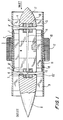
- FIG. 1 Only the major components of an axial flow turbo pump are shown in FIG. 1 in order to best describe the essential elements of the instant invention.
- An axial flow pump is illustrated and is not meant to be limiting.
- the same bearing suspension also applies to use in centrifugal turbo pumps. This is illustrated in the Goldowsky patent cited above.
- the pump rotor is generally depicted as item 18. It includes helical impeller blades 11, a round bearing item 2, magnet thrust bearings at each end, items 4 and 4', thin windows 10 and 10', brushless motor armature magnets item 13, and blood flow conduit hole 14 used to wash out the rotor gaps at each end.
- the concept of employing a central axial hole in the rotor to obtain gap washout flow is contained in Goldowsky U.S. patent No. 6,716,157 "Improved Magnetic Suspension Blood Pump", issued April 6, 2004.
- the magnet assemblies are hermetically sealed by thin (typically .010 thick) titanium or blood compatible sapphire window items 10.
- the bearing is separated from pump cylindrical housing 1 by radial blood gap 3, whose combination forms a conventional hydrodynamic bearing.
- the rotor has large axial blood gaps 5 and 5' at each end.
- the motor's brushless windings 12 surround the pump housing and are commutated to rotate the rotor.
- the outlet stator item 8 has a plurality of fixed, flow straightening vanes 9 that are attached to pump housing 1.
- the inlet stator 17 is fixed to the pump housing by flow inlet vanes 15.
- Each stator houses a thrust bearing magnet assembly generally designated item 4.
- a central hole in the magnet is optional, but one is shown as it is preferable that bearing 4 be identical to its co-linear mate 4'.
- Thrust bearings 4' are preferably located in each end of the rotor as shown to obtain bidirectional force capability.
- only one thrust bearing pair at the LVAD inlet is essential in order to hold differential pump pressure which is directed toward the pump inlet.
- the symmetrical axial portion of the magnetic fields emanating from each pair of magnets oppose one another making a repelling force.
- Typical bucking fields are shown dotted in FIGs. 2-5 (the matching bearing mate is not shown).
- the rotor is repelled in opposite axial directions at each end. This causes the rotor to find a stable central position under axial load.
- the thrust bearing is axis symmetric to allow rotation and this occurs with very low eddy current losses due to symmetry.
- a position sensor 16 uses rotor window item 10 as a target to monitor rotor axial position.
- the preferred sensor is a miniature ultrasound probe (typically 2mm in diameter) that operates from 5-15 mhz to have low attenuation in blood. It is insensitive to stray magnetic fields emanating from the thrust bearings and motor.
- the probe tip in contact with blood may have diamond-like coating for blood compatibility. This sensor only requires a flat rigid window surface for its sound-beam to reflect from. In operation, the probe generates a short burst of sound (pulse), and then monitors the time of flight of the return pulse to determine target range. Range is calculated knowing sound velocity in blood which is independent of blood viscosity and composition and gives stable performance.
- the position sensor may be conveniently located on or off the pump axis provided it sees the target to measure position of the rotor.
- An off axis location is depicted in FIG. 1 because this preferred rotor has an on axis blood washout hole, and the hole is an unsuitable target for such a small diameter transducer.
- Blood conduit 14 may be a titanium tube with an inside diameter of about 1-2mm. The choice of diameter will control the washout flow rate desired.
- the conduit may be a titanium tube for blood compatibility. It connects rotor gaps 5 and 5' in series with LVAD differential pressure which (typically 100 mmhg). The resulting flow actively washes out both gaps with frest blood to avoid thrombosis. There is a degree of centrifugal pressure generated in each gap 5 and 5', but they are equal and oppositely directed so their effects cancel. Pump differential pressure is the main driving force that actively washes out these gaps. This is discussed in detail in Goldowsky U.S. patent No. 6,716,157, issued April 6, 2004 entitled: "Improved Magnetic Suspension Blood Pump".
- FIG. 1 shows an axially magnetized cylindrical magnet 7. It is preferably neodymium iron boron or samarium cobalt for very high strength and resistance to the demagnetization load placed on it by its paired opposing magnet.
- An iron or preferably high saturation vanadium-permendure cylindrical cup 6 surrounds the magnet. The cup retains the magnet's flux and substantially reduces stray fields which could otherwise interfere with the motor armature magnets 18 and vice versa, particularly in a miniature pump where the thrust bearing is desired close to the motor magnets to minimize rotor length.
- FIG. 1 shows an axially magnetized cylindrical magnet 7. It is preferably neodymium iron boron or samarium cobalt for very high strength and resistance to the demagnetization load placed on it by its paired opposing magnet.
- An iron or preferably high saturation vanadium-permendure cylindrical cup 6 surrounds the magnet. The cup retains the magnet's flux and substantially reduces stray fields which could otherwise interfere with
- FIG. 3 shows the axial bucking field that emanates (shown dotted) from a similar geometry thrust bearing.
- the cup terminates at its outside diameter as a thin fringing ring item 6 whch is used to focus the magnet flux to a high level (greater than attainable with a pure magnet alone).
- This flux produces a stronger repulsion force (proportional to gap flux density squared) in a much smaller size than is attainable with a pure magnet alone.
- FIGs. 2 and 2A show the escaping or stray field emanating from a pure magnet. Its emanating axial field is weak and its axial force is small compared to that when a fringing ring is used. Fringing rings are ideally suited to minimize bearing size which is required in a miniature pump.
- FIG. 3 shows a thrust bearing geometry where a second fringing ring is located near to the center.
- the field emanates from the right end and when a matching bearing faces it, the two fields buck and repel. The closer they approach the higher the repulsion force which acts stably like a mechanical spring (negative stiffness) in the axial direction.
- the pair is mutually radial unstable (positive stiffness). The rotor tries to "kick out" at each thrust bearing.
- the magnet flux is concentrated higher in the fringe air gap of FIG. 3 than in the fringe air gap of the thrust bearing shown in FIG. 1. This is because the inner fringe has less cross sectional area than the outer, with the same amount of magnet flux, so its flux density is higher.
- the FIG. 3 bearing is preferred over FIG. 1 for performance but it requires an extra inner fringe.
- the hydrodynamic journal bearing is designed very stiffly in the radial direction to easily support the radial instability of the rotor's thrust bearings. Too large a thrust bearing axial stiffness is not desired because axial deflection under load will be too small to easily measure and because its radial instability stiffness becomes undesirably high. For resonance reasons there could be constraints on the journal bearing and thrust bearing stiffness.
- thrust bearing designs allow large gaps for ease of washout as well as large axial deflections.
- Use of large gaps 5 and 5' allow absorbing the energy of large shock loads without contact even for relatively low axial stiffness.
- a typical gap may be 0.3-3 mm and axial stiffness is easily tailored to be in the range of 20-200 lb/in.
- Another advantage of the iron cup used in bearings of FIGs. 1,3 and 5 is excellent axial force linearity. Constant axial stiffness is desirable for the rotor for dynamic analysis. A linear force displacement characteristic is also desirable for the differential pressure transducer for easy calibration. A pair of plain magnets (a single magnet is shown in FIG.2) is less desirable because it possesses a non-linear or exponential force. It is also much larger for the same stiffness and load capability and it has undesirable stray fields, detrimental in miniature and small pumps.
- FIGs. 1, 2, 2A, 3 and 3A show a single axial magnetized magnet item 7, the construction of the bearing in FIGs. 4 and 4A utilizes several radial magnetized magnet segments. This is the conventional way to obtain a radial magnetized rare earth magnet (one piece radial magnets are just becoming available). Thin circular iron rings 6" are located at the outside and inside diameters to capture the magnet's flux. The central hole (as in FIG.1 item 14) allows blood to flow therethrough. This configuration is not magnetically efficient because leakage flux passes around the left end as shown and is wasted. This can be compensated for using a longer magnet.
- FIG. 5 and 5A are similar in construction to FIG. 1 with an axial magnet but does not have a complete cup to shield the field. Some field is wasted that axially shunts around the outside diameter as shown. An internal finging ring 6' " is added to focus the remaining flux to increase the force. Both outer and inner fringing rings contribute to repulsive force, the inner one generally contributes most of the axial force in FIGs. 3, 3A. 4, 4A, 5 and 5A.
- the bearing assembly consists of the thin cylindrical bearing sleeve 2 rotating in round journal 1 axially. It is separated from the journal by radial bearing gap 3 which is blood immersed.
- the location of the bearing is preferably outside of and surrounds the impeller blades in order to eliminate a blood gap at the O.D. of blades 11 as well as not to occupy the space reserved for the motor magnets in the rotor hub.
- Blade gaps in conventional axial flow pumps like the Jarvik 2000 must be made small to reduce back leakage past them or pump efficiency suffers. This is most important for the small pumps, especially those designed for children.
- the impeller blade O.D. is bonded to the I.D. of bearing sleeve 2 or is made integral with it. No gap substantially improves pump hydraulic efficiency desirably reducing pump power.
- the housing bore is straight, rigid and ideally suited to being the journal.
- Bearing gap 3 is sized to be sufficiently large at the operating RPM of the pump to possess sub-hemolytic shear stresses. This minimizes blood hemolysis. However, the gap must be sufficiently small to produce the desired load capacity and radial stiffness over the LVAD's rpm operating envelope with variable blood viscosities. A larger gap is desired for low power loss. These constraints have been met in the instant invention. Practical operating gaps may fall in the range up to about 2mm for axial flow pumps typically operating 7,000-20,000 rpm. The design of the hydrodynamic bearing (gap, diameter and length) must be compatible with the impeller and operating rpm. Centrifugal turbo pumps on the other hand usually operate at much lower rpm (1,500-3,000). This necessitates use of a smaller gap.
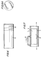
- FIGs. 6. 6A show a bearing that integrates a pressure generating screw pump at one end item 20 with a bearing portion item 19 of length L. It is similar to those shown in Goldowsky patent Nos. 5,924,975 (Linear Hydrodynamic Blood Pump) and 6,436,027 (Hydrodynamic Blood Bearing).
- FIGs. 6, 6A are the preferred design of the instant bearing. Only a short pump section 20 is needed particularly in axial flow turbo pumps because rpm is so high.
- the screw pump consists of a shallow helical screw thread of multiple starts. Blood is viscosity pumped along the thread grooves that are designed to generate pressure in excess of the outlet pressure of the LVAD (LVAD pressure typically 120 mmhg). The thread need only be a few mils deep allowing sleeve 2 to be thin to require little space. This creates continuous flow through the bearing continuously washing it out.
- the screw pump is preferably located near the pump inlet which is at low pressure. The screw pumps blood in one direction into the journal bearing gap and it exits at the bearing gap outlet to mix with LVAD blood. Since LVAD bulk blood is in the same direction as the gap flow, the two merge without regurgitation or back flow.
- Gap flow toward the LVAD outlet thereby eliminates stagnation regions to insure against thrombus formation at both bearing gap inlet and outlet.
- the screw pump flow is made sufficiently large so blood does not become heated in the bearing and to insure that a generous safety factor exists to wash out the gap under all operating conditions of the LVAD.
- a fluid groove (or inlet holes) is conventionally used in bearings not designed for blood, and is located at the center of the journal. The groove allows fluid to be passively drawn in. In an automobile engine, it is supplied under pressure by an external oil pump. This is possible to implement in the instant invention.
- the journal groove item 21 typically subtends 360 degrees to make load capacity symmetrical in angular direction and to wash out all areas. Arrows at the groove bottom depict bearing flow out of the groove toward each end of the bearing where it exists.
- the tube may alternatively be a hole in the wall of housing 1, but this is not practical for a thin wall, unless the wall is locally thickened.
- use of a central groove is not preferable compared to using an integral pump to supply pressurized-flow at the bearing end.
- a central groove undesirably reduces bearing load capacity by shortening bearing effective length L. This requires increasing bearing length to compensate. Grooves may also be prone to areas of stagnation that may clot with incipient bearing failure.
- An integrated compact pump such as the screw pump located at the end of hydrodynamic bearing 19 in FIG. 6, has been reliably used in blood with insignificant blood damage. This is an ideal solution to wash out the bearing.
- the length of the cylindrical bearing portion 19, labeled L is maximized and is not broken up as when the screw is located at the center of the bearing.
- An end location provides a longer effective bearing length that maximizes load capacity and this allows use of a larger radial gap. A larger gap has reduced blood shear stresses and less hemolysis.
- Hemolysis in an integrated hydrodynamic bearing/screw pump that was designed demonstrated a level for just the bearing that is 25 times lower (0.2) than is characteristic of turbo pumps (5mg/dl).
- a high pressure is needed to wash out the gap from one end so flow can be steady and sufficient. If no pressurizing pump is used to wash out the bearing gap, then one can use LVAD differential pressure alone (gap flow will be toward LVAD inlet) which is only about 100 mmhg. The gap can completely wash out using this relatively low pressure only if the internal hydrodynamic pressure pumping effect of the bearing is designed to be less. This internal pressure can be substantial. It is created by the rotating bearing and must be taken into account. Otherwise, a stagnant region will exist in the bearing and blood will clot causing bearing failure. Use of a pressurizing screw pump with sufficient pressure and flow avoids this, it is non-contacting, and it automatically operates with the bearing.
- pump-less washout has hemodynamic reliability concerns.
- a unidirectional screw pump that directs bearing gap flow toward the LVAD outlet is superior. It eliminates this problem and will provide superior long term hemodynamic reliability.
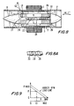
- FIG. 8 An alternate thrust bearing without magnets, is shown in FIG. 8.
- This is a hydro-static thrust bearing designed to hold axial load in one direction that is imposed by pump differential pressure. It has the desired stable negative axial stiffness possessing deflections that are much larger than in hydrodynamic thrust bearings. Its axial deflection under LVAD pressure loads is accurately measured using the preferred ultrasonic sensor discussed.
- a journal bearing with a hydrostatic thrust bearing designed to deliver cooling oil or water to electronic chips is disclosed in Goldowsky patent No. 5,713,670 titled: Self Pressurizing Journal Bearing Assembly. It is not tailored to work in blood but is similar.
- the inlet stator 17 (or alternatively outlet stator) uses an attached stationary helical screw 23 that has a single or multiple start thread. It is provided enlarged in FIG. 8A for clarity. Thread lands 28 may be long or short. Thread groove 29 is typically flat-bottomed and corner radii 30 are employed for good washout.
- the screw is small enough in diameter not to appreciably take space from the motor armature magnets which can be made longer to compensate.
- cylindrical passage 14 may have an internal helical screw thread; in this case a round pin is employed.
- the screw shaft may be supported at both ends. The screw is located on the rotor center line with a radial gap 24 that never contacts by virtue of the stiffness of hydrodynamic bearing 2 whose gap is 3.
- the tip of the screw may be an off-center point to divert flow non-symmetrically without a stagnation point, as may be the design of item 27.
- PL is increased by screw pump 23 to higher value PH at the screw outlet which enters gap G1.
- Gap G1 is much smaller than gap G2, thereby becoming the primary flow resistance on the screw pump. It is large enough to be subhemolytic.
- G1 forms a hydrostatic thrust bearing by virtue of the high pressure therein. Its thrust bearing area is equal to the end face area of the rotor hub (which is preferably the same at both ends as shown).
- Gap G1 discharges blood 26' to LVAD inlet pressure which is low.
- This unique combination or system of a screw pump and thrust bearing automatically adjusts rotor gap G1 using hydraulic feedback until the thrust bearing force equals the externally applied rotor force.
- This automatic adjusting of rotor axial position is measured with a position sensor from which differential pressure is calculated by dividing by the effective area of the rotor.
- a feedback system exists to drive rotor error position to zero because of the negative slope (pressure P versus flow Q) being inherent in the characteristic curves of screw pump 23.
- Schematic screw pump curves are shown in FIG. 9. The two “curves” are linear with the upper one being at higher rpm. These lines are parallel and linearly spaced apart as a function of rpm.
- Q max maximum value
- Q max maximum pressure rise
- Q max maximum pressure rise
- the amount of flow Q at a given pressure P is shown dotted which gives the typical operating point; and so operating gap G1 results, it being shown on the lower horizontal scale.
- G1 is zero, no flow can occur and when G1 is some maximum value, pressure P drops to zero.
- G2 is always large even at bearing lift-off and has no effect.
- This pressure transducer provides a means to determine the onset of inlet suction so it can be avoided.
- a fast-rising spike in differential pressure and its magnitude characterize suction. Avoiding this is important to obtain safe physiologic control with pulsating flow.
- Constant rpm LVADs have much less of a problem because their flow rates can be conservatively set without providing pulsating flow.
- the instant pressure transducer allows one to measure the pressure produced by the patient's beating heart (and the heart's state of recovery) independently of the pulsating pressure produced by the LVAD (which can be programmed at a differing frequency).
- a screw pump operates by pumping fluid (blood) along the screw whose gross flow rate is theoretically independent of fluid viscosity.
- forward gross flow is reduced by back-leakage over the threads which depend on blood viscosity (for laminar flow past the threads).
- Laminar back flow can be made very small using long lands 28 instead of a smaller gap which has undesirable higher shear stress.
- a long length screw is advantageous to accomplish this (a long summed length of series lands) because space exists for a long screw in this preferred design.
- One may also elect to use a larger gap 24 with short thread lands to produce orifice flow. Orifice back flow is viscosity independent. Therefore, it is clear thrust bearing calibration can be made insensitive to blood viscosity (which is variable with hematocrit) for reliable long-term use.
- the proposed thrust bearing's (force - deflection) characteristic is linear because a linear load line screw pump is employed as the pressure source (P versus Q is linear). However, rpm must be used to know which characteristic pump curve is in effect. This gives the final piece of real time information needed to calibrate rotor displacement. If a centrifugal type pump is used as the pressure source instead of a screw, then a plain central hole 14 is employed like in FIG. 1. The P versus Q curve is non-linear for centrifugal pumps and pressure rise depends on the square of rpm. A centrifugal type pump is usable (if employed on its negative slope) since its characteristic curves are insensitive to blood viscosity.
- a centrifugal pump is integrated in the instant invention by providing a plurality of small blades on the rotor in gap G1. This is shown in FIG. 16 of the Goldowsky patent No. 6,527,699 titled: Magnetic Blood Pump, to wash out the bearing gaps of the rotor.
Landscapes
- Health & Medical Sciences (AREA)
- Heart & Thoracic Surgery (AREA)
- Engineering & Computer Science (AREA)
- Cardiology (AREA)
- Life Sciences & Earth Sciences (AREA)
- Public Health (AREA)
- Biomedical Technology (AREA)
- Hematology (AREA)
- Mechanical Engineering (AREA)
- Animal Behavior & Ethology (AREA)
- General Health & Medical Sciences (AREA)
- Anesthesiology (AREA)
- Veterinary Medicine (AREA)
- Physics & Mathematics (AREA)
- Fluid Mechanics (AREA)
- Structures Of Non-Positive Displacement Pumps (AREA)
- External Artificial Organs (AREA)
- Magnetic Bearings And Hydrostatic Bearings (AREA)
Applications Claiming Priority (4)
| Application Number | Priority Date | Filing Date | Title |
|---|---|---|---|
| US845183 | 1997-04-25 | ||
| US47358703P | 2003-05-28 | 2003-05-28 | |
| US473587P | 2003-05-28 | ||
| US10/845,183 US20040241019A1 (en) | 2003-05-28 | 2004-05-14 | Passive non-contacting smart bearing suspension for turbo blood-pumps |
Publications (1)
| Publication Number | Publication Date |
|---|---|
| EP1481699A1 true EP1481699A1 (fr) | 2004-12-01 |
Family
ID=33135330
Family Applications (1)
| Application Number | Title | Priority Date | Filing Date |
|---|---|---|---|
| EP20040102209 Withdrawn EP1481699A1 (fr) | 2003-05-28 | 2004-05-19 | Suspension passive sans contact pour un palier d'une turbopompe a sang |
Country Status (8)
| Country | Link |
|---|---|
| US (1) | US20040241019A1 (fr) |
| EP (1) | EP1481699A1 (fr) |
| JP (1) | JP2004351213A (fr) |
| CN (1) | CN1572331A (fr) |
| BR (1) | BRPI0401836A (fr) |
| CA (1) | CA2468546A1 (fr) |
| IL (1) | IL162074A0 (fr) |
| MX (1) | MXPA04005067A (fr) |
Cited By (20)
| Publication number | Priority date | Publication date | Assignee | Title |
|---|---|---|---|---|
| WO2005028872A3 (fr) * | 2003-09-18 | 2005-09-15 | Myrakelle Llc | Pompe a sang rotative |
| US7134381B2 (en) | 2003-08-21 | 2006-11-14 | Nissan Motor Co., Ltd. | Refrigerant compressor and friction control process therefor |
| US7146956B2 (en) | 2003-08-08 | 2006-12-12 | Nissan Motor Co., Ltd. | Valve train for internal combustion engine |
| US7228786B2 (en) | 2003-06-06 | 2007-06-12 | Nissan Motor Co., Ltd. | Engine piston-pin sliding structure |
| US7255083B2 (en) | 2002-10-16 | 2007-08-14 | Nissan Motor Co., Ltd. | Sliding structure for automotive engine |
| US7273655B2 (en) | 1999-04-09 | 2007-09-25 | Shojiro Miyake | Slidably movable member and method of producing same |
| US7284525B2 (en) | 2003-08-13 | 2007-10-23 | Nissan Motor Co., Ltd. | Structure for connecting piston to crankshaft |
| US7318514B2 (en) | 2003-08-22 | 2008-01-15 | Nissan Motor Co., Ltd. | Low-friction sliding member in transmission, and transmission oil therefor |
| US7322749B2 (en) | 2002-11-06 | 2008-01-29 | Nissan Motor Co., Ltd. | Low-friction sliding mechanism |
| US7406940B2 (en) | 2003-05-23 | 2008-08-05 | Nissan Motor Co., Ltd. | Piston for internal combustion engine |
| US7458585B2 (en) | 2003-08-08 | 2008-12-02 | Nissan Motor Co., Ltd. | Sliding member and production process thereof |
| US7500472B2 (en) | 2003-04-15 | 2009-03-10 | Nissan Motor Co., Ltd. | Fuel injection valve |
| US7572200B2 (en) | 2003-08-13 | 2009-08-11 | Nissan Motor Co., Ltd. | Chain drive system |
| US7771821B2 (en) | 2003-08-21 | 2010-08-10 | Nissan Motor Co., Ltd. | Low-friction sliding member and low-friction sliding mechanism using same |
| US8096205B2 (en) | 2003-07-31 | 2012-01-17 | Nissan Motor Co., Ltd. | Gear |
| US8206035B2 (en) | 2003-08-06 | 2012-06-26 | Nissan Motor Co., Ltd. | Low-friction sliding mechanism, low-friction agent composition and method of friction reduction |
| US9512852B2 (en) | 2006-03-31 | 2016-12-06 | Thoratec Corporation | Rotary blood pump |
| FR3071282A1 (fr) * | 2017-09-21 | 2019-03-22 | Fineheart | Turbine a pales internes |
| WO2019217426A1 (fr) * | 2018-05-10 | 2019-11-14 | Heartware, Inc. | Algorithme de pression de pompe axiale à commande orientée de champ |
| US11311711B2 (en) | 2018-01-31 | 2022-04-26 | Heartware, Inc. | Axial blood pump with impeller rinse operation |
Families Citing this family (92)
| Publication number | Priority date | Publication date | Assignee | Title |
|---|---|---|---|---|
| US7118356B2 (en) * | 2002-10-02 | 2006-10-10 | Nanyang Technological University | Fluid pump with a tubular driver body capable of selective axial expansion and contraction |
| US8419609B2 (en) | 2005-10-05 | 2013-04-16 | Heartware Inc. | Impeller for a rotary ventricular assist device |
| US7972122B2 (en) | 2005-04-29 | 2011-07-05 | Heartware, Inc. | Multiple rotor, wide blade, axial flow pump |
| US7226277B2 (en) * | 2004-12-22 | 2007-06-05 | Pratt & Whitney Canada Corp. | Pump and method |
| EP1898971B1 (fr) | 2005-06-06 | 2015-03-11 | The Cleveland Clinic Foundation | Pompe sanguine |
| EP1738783A1 (fr) * | 2005-07-01 | 2007-01-03 | Universitätsspital Basel | Pompe axiale avec une aube hélicoïdale |
| JP4176753B2 (ja) * | 2005-08-19 | 2008-11-05 | 三菱重工業株式会社 | 人工心臓ポンプ |
| JP4512149B2 (ja) * | 2005-08-19 | 2010-07-28 | 三菱重工業株式会社 | 人工心臓ポンプ |
| JP4209412B2 (ja) * | 2005-09-13 | 2009-01-14 | 三菱重工業株式会社 | 人工心臓ポンプ |
| US8672611B2 (en) | 2006-01-13 | 2014-03-18 | Heartware, Inc. | Stabilizing drive for contactless rotary blood pump impeller |
| EP3954901A1 (fr) | 2006-01-13 | 2022-02-16 | HeartWare, Inc. | Pompe sanguine rotative |
| US9028392B2 (en) * | 2006-12-01 | 2015-05-12 | NuCardia, Inc. | Medical device |
| US20090112312A1 (en) * | 2007-02-26 | 2009-04-30 | Larose Jeffrey A | Intravascular ventricular assist device |
| WO2008140278A2 (fr) * | 2007-05-16 | 2008-11-20 | Jong-Gwan Geum | Motopompe |
| US7828710B2 (en) * | 2007-06-05 | 2010-11-09 | Medical Value Partners, Llc | Apparatus comprising a drive cable for a medical device |
| US8079948B2 (en) | 2007-08-29 | 2011-12-20 | NuCardia, Inc. | Article comprising an impeller |
| DE102010056260A1 (de) | 2010-12-24 | 2012-06-28 | Christian Zschoch | Hydro-magnetisches Zentrifugallager mit nutzbarer Rotationswelle |
| WO2012094641A2 (fr) * | 2011-01-06 | 2012-07-12 | Thoratec Corporation | Pompe cardiaque percutanée |
| EP2846851A4 (fr) * | 2012-05-11 | 2016-01-20 | Heartware Inc | Stator de moteur en argent pour pompe à sang implantable |
| GB2504177B (en) | 2012-05-14 | 2014-12-10 | Thoratec Corp | Sheath system for catheter pump |
| GB2504176A (en) | 2012-05-14 | 2014-01-22 | Thoratec Corp | Collapsible impeller for catheter pump |
| US10111994B2 (en) | 2013-05-14 | 2018-10-30 | Heartware, Inc. | Blood pump with separate mixed-flow and axial-flow impeller stages and multi-stage stators |
| US9427508B2 (en) * | 2013-06-04 | 2016-08-30 | Heartware, Inc. | Axial flow pump pressure algorithm |
| US10357748B2 (en) | 2014-03-28 | 2019-07-23 | Asepco | Magnetically coupled mixer with thrust bearing friction control |
| US10363349B2 (en) | 2014-04-15 | 2019-07-30 | Tc1 Llp | Heart pump providing adjustable outflow |
| JP2016044673A (ja) * | 2014-08-22 | 2016-04-04 | 日本電産株式会社 | 動圧軸受ポンプ |
| JP2016044674A (ja) * | 2014-08-22 | 2016-04-04 | 日本電産株式会社 | 動圧軸受ポンプ |
| BR102014021617B1 (pt) * | 2014-09-01 | 2023-04-11 | Mundial S/A Produtos De Consumo | Motobomba de mancal flutuante arrefecida por um fluido circulante |
| CN104162191B (zh) * | 2014-09-05 | 2016-08-24 | 长治市久安人工心脏科技开发有限公司 | 一种液磁悬浮轴流式心脏辅助血泵 |
| ES2839081T3 (es) * | 2015-03-18 | 2021-07-05 | Abiomed Europe Gmbh | Bomba de sangre |
| WO2017015268A1 (fr) | 2015-07-20 | 2017-01-26 | Thoratec Corporation | Estimation de débit à l'aide de capteurs à effet hall |
| WO2017015210A1 (fr) * | 2015-07-20 | 2017-01-26 | Thoratec Corporation | Tensiomètre pour l'estimation de débit |
| EP3157145A1 (fr) * | 2015-10-13 | 2017-04-19 | Berlin Heart GmbH | Rotor pour une pompe et pompe et procede de montage |
| US10941781B2 (en) * | 2015-11-10 | 2021-03-09 | Pierburg Pump Technology Gmbh | Electric motor vehicle axial-flow liquid pump |
| US10213537B2 (en) * | 2016-07-19 | 2019-02-26 | Heartware, Inc. | Ventricular assist devices and integrated sensors thereof |
| US10851791B2 (en) | 2016-12-19 | 2020-12-01 | Okinawa Institute Of Science And Technology School Corporation | Contactless magnetic couplings for microfluidic devices and nautical propulsion |
| EP4732889A2 (fr) | 2017-06-07 | 2026-04-29 | Supira Medical, Inc. | Dispositifs de déplacement de fluide intravasculaire, systèmes et procédés d'utilisation |
| US11511103B2 (en) | 2017-11-13 | 2022-11-29 | Shifamed Holdings, Llc | Intravascular fluid movement devices, systems, and methods of use |
| EP3720520B1 (fr) | 2017-12-05 | 2024-07-03 | Heartware, Inc. | Pompe à sang avec opération de rinçage de roue |
| CN115025386B (zh) * | 2018-01-10 | 2025-07-25 | 马真塔医药有限公司 | 心室辅助装置 |
| DE102018201030B4 (de) | 2018-01-24 | 2025-10-16 | Kardion Gmbh | Magnetkuppelelement mit magnetischer Lagerungsfunktion |
| JP7410034B2 (ja) | 2018-02-01 | 2024-01-09 | シファメド・ホールディングス・エルエルシー | 血管内血液ポンプならびに使用および製造の方法 |
| DE102018207575A1 (de) | 2018-05-16 | 2019-11-21 | Kardion Gmbh | Magnetische Stirndreh-Kupplung zur Übertragung von Drehmomenten |
| DE102018207611A1 (de) | 2018-05-16 | 2019-11-21 | Kardion Gmbh | Rotorlagerungssystem |
| DE102018207594A1 (de) | 2018-05-16 | 2019-11-21 | Kardion Gmbh | Rotor, Magnetkupplungsvorrichtung, Elektromotor für ein Herzunterstützungssystem, Pumpeneinheit für ein Herzunterstützungssystem sowie Verfahren zum Herstellen eines Rotors |
| DE102018208549A1 (de) | 2018-05-30 | 2019-12-05 | Kardion Gmbh | Elektronikmodul für ein Herzunterstützungssystem und Verfahren zum Herstellen eines Elektronikmoduls für ein Herzunterstützungssystem |
| DE102018208538A1 (de) | 2018-05-30 | 2019-12-05 | Kardion Gmbh | Intravasale Blutpumpe und Verfahren zur Herstellung von elektrischen Leiterbahnen |
| DE102018208541A1 (de) | 2018-05-30 | 2019-12-05 | Kardion Gmbh | Axialpumpe für ein Herzunterstützungssystem und Verfahren zum Herstellen einer Axialpumpe für ein Herzunterstützungssystem |
| DE102018208550A1 (de) | 2018-05-30 | 2019-12-05 | Kardion Gmbh | Leitungsvorrichtung zum Leiten eines Blutstroms für ein Herzunterstützungssystem, Herzunterstützungssystem und Verfahren zum Herstellen einer Leitungsvorrichtung |
| DE102018208539A1 (de) | 2018-05-30 | 2019-12-05 | Kardion Gmbh | Motorgehäusemodul zum Abdichten eines Motorraums eines Motors eines Herzunterstützungssystems und Herzunterstützungssystem und Verfahren zum Montieren eines Herzunterstützungssystems |
| DE102018208899A1 (de) | 2018-06-06 | 2019-12-12 | Kardion Gmbh | Verfahren zum Ermitteln der Schallgeschwindigkeit in einem Fluid im Bereich eines implantierten, vaskulären Unterstützungssystems |
| DE102018208931A1 (de) | 2018-06-06 | 2019-12-12 | Kardion Gmbh | Vorrichtung zum Bestimmen eines Herzzeitvolumens für ein Herzunterstützungssystem, Herzunterstützungssystem und Verfahren zum Bestimmen eines Herzzeitvolumens |
| DE102018208879A1 (de) | 2018-06-06 | 2020-01-30 | Kardion Gmbh | Verfahren zur Bestimmung eines Fluid-Gesamtvolumenstroms im Bereich eines implantierten, vaskuläres Unterstützungssystems |
| DE102018208933A1 (de) | 2018-06-06 | 2019-12-12 | Kardion Gmbh | Verfahren zur Bestimmung einer Strömungsgeschwindigkeit eines durch ein implantiertes, vaskuläres Unterstützungssystem strömenden Fluids |
| DE102018208870A1 (de) | 2018-06-06 | 2019-12-12 | Kardion Gmbh | Verfahren zur Bestimmung eines Fluid-Volumenstroms durch ein implantiertes, vaskuläres Unterstützungssystem |
| DE102018208945A1 (de) | 2018-06-06 | 2019-12-12 | Kardion Gmbh | Analysevorrichtung und Verfahren zum Analysieren einer Viskosität eines Fluids |
| DE102018208862A1 (de) | 2018-06-06 | 2019-12-12 | Kardion Gmbh | Implantierbares, vaskuläres Unterstützungssystem |
| DE102018208913A1 (de) | 2018-06-06 | 2019-12-12 | Kardion Gmbh | Verfahren zum Betreiben eines implantierten, ventrikulären Unterstützungssystems |
| DE102018208892A1 (de) | 2018-06-06 | 2019-12-12 | Kardion Gmbh | Sensorkopfvorrichtung für ein minimalinvasives Herzunterstützungssystem und Verfahren zum Herstellen einer Sensorkopfvorrichtung für ein Herzunterstützungssystem |
| DE102018208936A1 (de) | 2018-06-06 | 2019-12-12 | Kardion Gmbh | Bestimmvorrichtung und Verfahren zum Bestimmen einer Viskosität eines Fluids |
| DE102018208929A1 (de) | 2018-06-06 | 2019-12-12 | Kardion Gmbh | Verfahren zur Bestimmung einer Strömungsgeschwindigkeit eines durch ein implantiertes, vaskuläres Unterstützungssystem strömenden Fluids |
| DE102018210058A1 (de) | 2018-06-21 | 2019-12-24 | Kardion Gmbh | Statorschaufelvorrichtung zur Strömungsführung eines aus einer Austrittsöffnung eines Herzunterstützungssystems ausströmenden Fluids, Herzunterstützungssystem mit Statorschaufelvorrichtung, Verfahren zum Betreiben einer Statorschaufelvorrichtung und Herstellverfahren |
| DE102018210076A1 (de) | 2018-06-21 | 2019-12-24 | Kardion Gmbh | Verfahren und Vorrichtung zum Erkennen eines Verschleißzustands eines Herzunterstützungssystems, Verfahren und Vorrichtung zum Betreiben eines Herzunterstützungssystems und Herzunterstützungssystem |
| DE102018211297A1 (de) | 2018-07-09 | 2020-01-09 | Kardion Gmbh | Herzunterstützungssystem und Verfahren zur Überwachung der Integrität einer Haltestruktur eines Herzunterstützungssystems |
| DE102018211327A1 (de) | 2018-07-10 | 2020-01-16 | Kardion Gmbh | Laufrad für ein implantierbares, vaskuläres Unterstützungssystem |
| DE102018211328A1 (de) | 2018-07-10 | 2020-01-16 | Kardion Gmbh | Laufradgehäuse für ein implantierbares, vaskuläres Unterstützungssystem |
| DE102018212153A1 (de) | 2018-07-20 | 2020-01-23 | Kardion Gmbh | Zulaufleitung für eine Pumpeneinheit eines Herzunterstützungssystems, Herzunterstützungssystem und Verfahren zum Herstellen einer Zulaufleitung für eine Pumpeneinheit eines Herzunterstützungssystems |
| WO2020028537A1 (fr) | 2018-07-31 | 2020-02-06 | Shifamed Holdings, Llc | Pompes sanguines intravasculaires et procédés d'utilisation |
| AU2019320533B2 (en) | 2018-08-07 | 2024-11-21 | Kardion Gmbh | Bearing device for a cardiac support system, and method for flushing an intermediate space in a bearing device for a cardiac support system |
| DE102018213350A1 (de) | 2018-08-08 | 2020-02-13 | Kardion Gmbh | Vorrichtung und Verfahren zur Überwachung eines Gesundheitszustands des Patienten |
| WO2020073047A1 (fr) | 2018-10-05 | 2020-04-09 | Shifamed Holdings, Llc | Pompes à sang intravasculaires et procédés d'utilisation |
| CN109441836B (zh) * | 2018-12-10 | 2024-06-14 | 深圳兴奇宏科技有限公司 | 薄型泵浦结构 |
| CN111375098B (zh) * | 2018-12-29 | 2023-04-07 | 上海微创心力医疗科技有限公司 | 经皮血泵及其转子限位结构 |
| CN109821084B (zh) * | 2019-03-22 | 2019-10-29 | 河海大学 | 一种基于流道渐变的可植入无轴心脏泵 |
| FR3095017B1 (fr) * | 2019-04-10 | 2021-11-26 | Fineheart | Pivot de sortie pour pompe cardiaque à couplage magnétique. |
| WO2021011473A1 (fr) | 2019-07-12 | 2021-01-21 | Shifamed Holdings, Llc | Pompes à sang intravasculaires et méthode d'utilisation et procédé de fabrication |
| US11654275B2 (en) | 2019-07-22 | 2023-05-23 | Shifamed Holdings, Llc | Intravascular blood pumps with struts and methods of use and manufacture |
| EP4010046A4 (fr) | 2019-08-07 | 2023-08-30 | Calomeni, Michael | Pompes sanguines à cathéter et boîtiers de pompe pliants |
| US12171994B2 (en) * | 2019-09-11 | 2024-12-24 | Boston Scientific Scimed, Inc. | Reduced thrombosis blood pump with washout bearing |
| WO2021062260A1 (fr) | 2019-09-25 | 2021-04-01 | Shifamed Holdings, Llc | Pompes à sang de cathéter et conduits sanguins pliables |
| EP4034192B1 (fr) | 2019-09-25 | 2025-12-24 | Supira Medical, Inc. | Dispositifs et systèmes de pompes à sang intravasculaires et leurs procédés d'utilisation et de commande |
| EP4034221B1 (fr) | 2019-09-25 | 2024-11-13 | Shifamed Holdings, LLC | Pompes à sang de cathéter et boîtiers de pompe pliables |
| EP4072650A4 (fr) | 2019-12-11 | 2024-01-10 | Shifamed Holdings, LLC | Pompes à sang d'aorte descendante et de veine cave |
| US12599758B2 (en) | 2019-12-19 | 2026-04-14 | Shifamed Holdings, Llc | Intravascular blood pumps, motors, and fluid control |
| DE102020102474A1 (de) | 2020-01-31 | 2021-08-05 | Kardion Gmbh | Pumpe zum Fördern eines Fluids und Verfahren zum Herstellen einer Pumpe |
| CA3192451A1 (fr) | 2020-09-14 | 2022-03-17 | Johannes Bette | Pompe de support cardiovasculaire dotee d'un impulseur a zone d'ecoulement variable |
| JP2023550938A (ja) | 2020-11-20 | 2023-12-06 | カルディオン ゲーエムベーハー | ガイドワイヤ補助具付き機械的循環支持システム |
| JP2024525097A (ja) | 2021-07-07 | 2024-07-09 | エフビーアール メディカル, インク. | 部分的に変形可能なインペラ及び同インペラを組み込んだカテーテル血液ポンプ |
| WO2023043973A1 (fr) * | 2021-09-17 | 2023-03-23 | Abiomed, Inc. | Pompe à sang intravasculaire |
| US12502524B2 (en) | 2021-12-03 | 2025-12-23 | Kardion Gmbh | Cardiac pump with optical fiber for laser doppler |
| CN114165456B (zh) * | 2021-12-17 | 2022-10-28 | 浙江大学 | 一种基于磁液双悬浮结构的离心泵 |
| CN114367034B (zh) * | 2022-01-22 | 2023-08-22 | 上海炫脉医疗科技有限公司 | 一种带一体式叶轮结构的轴流式血泵 |
Citations (6)
| Publication number | Priority date | Publication date | Assignee | Title |
|---|---|---|---|---|
| US5470208A (en) * | 1990-10-05 | 1995-11-28 | Kletschka; Harold D. | Fluid pump with magnetically levitated impeller |
| US5685700A (en) * | 1995-06-01 | 1997-11-11 | Advanced Bionics, Inc. | Bearing and seal-free blood pump |
| US6071093A (en) * | 1996-10-18 | 2000-06-06 | Abiomed, Inc. | Bearingless blood pump and electronic drive system |
| WO2000064030A1 (fr) * | 1999-04-20 | 2000-10-26 | Berlin Heart Ag | Dispositif pour refouler des substances fluides a une ou a plusieurs phases sans les alterer |
| WO2000074748A1 (fr) * | 1999-06-03 | 2000-12-14 | Goldowsky Michael P | Pompe a sang a suspension magnetique |
| WO2002066837A1 (fr) | 2001-02-16 | 2002-08-29 | Berlin Heart Ag | Dispositif de transport axial de liquides |
Family Cites Families (6)
| Publication number | Priority date | Publication date | Assignee | Title |
|---|---|---|---|---|
| US5209650A (en) * | 1991-02-28 | 1993-05-11 | Lemieux Guy B | Integral motor and pump |
| JP4390856B2 (ja) * | 1996-09-10 | 2009-12-24 | レビトロニクス エルエルシー | ロータリー・ポンプ及びその駆動方法 |
| DE19944863A1 (de) * | 1999-09-18 | 2001-04-19 | Forschungszentrum Juelich Gmbh | Magnetlager |
| US6595743B1 (en) * | 1999-07-26 | 2003-07-22 | Impsa International Inc. | Hydraulic seal for rotary pumps |
| US6527699B1 (en) * | 2000-06-02 | 2003-03-04 | Michael P. Goldowsky | Magnetic suspension blood pump |
| US7052253B2 (en) * | 2003-05-19 | 2006-05-30 | Advanced Bionics, Inc. | Seal and bearing-free fluid pump incorporating a passively suspended self-positioning impeller |
-
2004
- 2004-05-14 US US10/845,183 patent/US20040241019A1/en not_active Abandoned
- 2004-05-19 EP EP20040102209 patent/EP1481699A1/fr not_active Withdrawn
- 2004-05-19 IL IL16207404A patent/IL162074A0/xx unknown
- 2004-05-27 MX MXPA04005067A patent/MXPA04005067A/es not_active Application Discontinuation
- 2004-05-27 BR BR0401836-2A patent/BRPI0401836A/pt not_active IP Right Cessation
- 2004-05-27 CA CA002468546A patent/CA2468546A1/fr not_active Abandoned
- 2004-05-28 CN CNA2004100472916A patent/CN1572331A/zh active Pending
- 2004-05-28 JP JP2004159179A patent/JP2004351213A/ja not_active Withdrawn
Patent Citations (7)
| Publication number | Priority date | Publication date | Assignee | Title |
|---|---|---|---|---|
| US5470208A (en) * | 1990-10-05 | 1995-11-28 | Kletschka; Harold D. | Fluid pump with magnetically levitated impeller |
| US5685700A (en) * | 1995-06-01 | 1997-11-11 | Advanced Bionics, Inc. | Bearing and seal-free blood pump |
| US6071093A (en) * | 1996-10-18 | 2000-06-06 | Abiomed, Inc. | Bearingless blood pump and electronic drive system |
| WO2000064030A1 (fr) * | 1999-04-20 | 2000-10-26 | Berlin Heart Ag | Dispositif pour refouler des substances fluides a une ou a plusieurs phases sans les alterer |
| WO2000074748A1 (fr) * | 1999-06-03 | 2000-12-14 | Goldowsky Michael P | Pompe a sang a suspension magnetique |
| WO2002066837A1 (fr) | 2001-02-16 | 2002-08-29 | Berlin Heart Ag | Dispositif de transport axial de liquides |
| US20040115038A1 (en) | 2001-02-16 | 2004-06-17 | Peter Nuesser | Device for axially conveying fluids |
Cited By (42)
| Publication number | Priority date | Publication date | Assignee | Title |
|---|---|---|---|---|
| US7273655B2 (en) | 1999-04-09 | 2007-09-25 | Shojiro Miyake | Slidably movable member and method of producing same |
| US7255083B2 (en) | 2002-10-16 | 2007-08-14 | Nissan Motor Co., Ltd. | Sliding structure for automotive engine |
| US7322749B2 (en) | 2002-11-06 | 2008-01-29 | Nissan Motor Co., Ltd. | Low-friction sliding mechanism |
| US8152377B2 (en) * | 2002-11-06 | 2012-04-10 | Nissan Motor Co., Ltd. | Low-friction sliding mechanism |
| US7500472B2 (en) | 2003-04-15 | 2009-03-10 | Nissan Motor Co., Ltd. | Fuel injection valve |
| US7406940B2 (en) | 2003-05-23 | 2008-08-05 | Nissan Motor Co., Ltd. | Piston for internal combustion engine |
| US7228786B2 (en) | 2003-06-06 | 2007-06-12 | Nissan Motor Co., Ltd. | Engine piston-pin sliding structure |
| US8096205B2 (en) | 2003-07-31 | 2012-01-17 | Nissan Motor Co., Ltd. | Gear |
| US8206035B2 (en) | 2003-08-06 | 2012-06-26 | Nissan Motor Co., Ltd. | Low-friction sliding mechanism, low-friction agent composition and method of friction reduction |
| US7458585B2 (en) | 2003-08-08 | 2008-12-02 | Nissan Motor Co., Ltd. | Sliding member and production process thereof |
| US8575076B2 (en) | 2003-08-08 | 2013-11-05 | Nissan Motor Co., Ltd. | Sliding member and production process thereof |
| US7146956B2 (en) | 2003-08-08 | 2006-12-12 | Nissan Motor Co., Ltd. | Valve train for internal combustion engine |
| US7284525B2 (en) | 2003-08-13 | 2007-10-23 | Nissan Motor Co., Ltd. | Structure for connecting piston to crankshaft |
| US7572200B2 (en) | 2003-08-13 | 2009-08-11 | Nissan Motor Co., Ltd. | Chain drive system |
| US7771821B2 (en) | 2003-08-21 | 2010-08-10 | Nissan Motor Co., Ltd. | Low-friction sliding member and low-friction sliding mechanism using same |
| US7134381B2 (en) | 2003-08-21 | 2006-11-14 | Nissan Motor Co., Ltd. | Refrigerant compressor and friction control process therefor |
| US7318514B2 (en) | 2003-08-22 | 2008-01-15 | Nissan Motor Co., Ltd. | Low-friction sliding member in transmission, and transmission oil therefor |
| US7650976B2 (en) | 2003-08-22 | 2010-01-26 | Nissan Motor Co., Ltd. | Low-friction sliding member in transmission, and transmission oil therefor |
| US7416525B2 (en) | 2003-09-18 | 2008-08-26 | Myrakelle, Llc | Rotary blood pump |
| US8807968B2 (en) | 2003-09-18 | 2014-08-19 | Thoratec Corporation | Rotary blood pump with opposing spindle magnets, bore and drive windings |
| US7753645B2 (en) | 2003-09-18 | 2010-07-13 | Thoratec Corporation | Rotary blood pump with opposing spindle magnets and contoured housing |
| US8118724B2 (en) | 2003-09-18 | 2012-02-21 | Thoratec Corporation | Rotary blood pump |
| US7682301B2 (en) | 2003-09-18 | 2010-03-23 | Thoratec Corporation | Rotary blood pump |
| US7431688B2 (en) | 2003-09-18 | 2008-10-07 | Myrakelle, Llc | Rotary blood pump |
| WO2005028872A3 (fr) * | 2003-09-18 | 2005-09-15 | Myrakelle Llc | Pompe a sang rotative |
| US8579607B2 (en) | 2003-09-18 | 2013-11-12 | Thoratec Corporation | Rotary blood pump with opposing spindle magnets, bore and drive windings |
| US8684902B2 (en) | 2003-09-18 | 2014-04-01 | Thoratec Corporation | Rotary blood pump |
| US10391215B2 (en) | 2003-09-18 | 2019-08-27 | Tc1 Llc | Rotary blood pump with opposing spindle magnets, bore and drive windings |
| US8834342B2 (en) | 2003-09-18 | 2014-09-16 | Thoratec Corporation | Rotary blood pump |
| US7802966B2 (en) | 2003-09-18 | 2010-09-28 | Thoratec Corporation | Rotary blood pump |
| US9533083B2 (en) | 2003-09-18 | 2017-01-03 | Thoratec Corporation | Methods of operating a rotary blood pump |
| US9545467B2 (en) | 2003-09-18 | 2017-01-17 | Thoratec Corporation | Rotary blood pump with opposing spindle magnets, bore and drive windings |
| US9844617B2 (en) | 2003-09-18 | 2017-12-19 | Tc1 Llc | Rotary blood pump with opposing spindle magnets, bore and drive windings |
| US10034972B2 (en) | 2003-09-18 | 2018-07-31 | Tc1 Llc | Rotary blood pump with opposing spindle magnets, bore and drive windings |
| US10751454B2 (en) | 2003-09-18 | 2020-08-25 | Tc1 Llc | Rotary blood pump with opposing spindle magnets, bore and drive windings |
| US9512852B2 (en) | 2006-03-31 | 2016-12-06 | Thoratec Corporation | Rotary blood pump |
| WO2019057776A1 (fr) * | 2017-09-21 | 2019-03-28 | Fineheart | Turbine a pales internes |
| FR3071282A1 (fr) * | 2017-09-21 | 2019-03-22 | Fineheart | Turbine a pales internes |
| US10954954B2 (en) | 2017-09-21 | 2021-03-23 | Fineheart | Turbine with internal blades |
| US11311711B2 (en) | 2018-01-31 | 2022-04-26 | Heartware, Inc. | Axial blood pump with impeller rinse operation |
| WO2019217426A1 (fr) * | 2018-05-10 | 2019-11-14 | Heartware, Inc. | Algorithme de pression de pompe axiale à commande orientée de champ |
| US11446481B2 (en) * | 2018-05-10 | 2022-09-20 | Heartware, Inc. | Axial pump pressure algorithm with field oriented control |
Also Published As
| Publication number | Publication date |
|---|---|
| CN1572331A (zh) | 2005-02-02 |
| JP2004351213A (ja) | 2004-12-16 |
| US20040241019A1 (en) | 2004-12-02 |
| CA2468546A1 (fr) | 2004-11-28 |
| BRPI0401836A (pt) | 2005-05-24 |
| MXPA04005067A (es) | 2005-07-01 |
| IL162074A0 (en) | 2005-11-20 |
Similar Documents
| Publication | Publication Date | Title |
|---|---|---|
| EP1481699A1 (fr) | Suspension passive sans contact pour un palier d'une turbopompe a sang | |
| US20080262289A1 (en) | Blood Pump Having A Passive Non-Contacting Bearing Suspension | |
| US6527699B1 (en) | Magnetic suspension blood pump | |
| CA2253435C (fr) | Appareil de pompage rotatif hybride combinant sustentation magnetique et force centrifuge et procede | |
| US5507629A (en) | Artificial hearts with permanent magnet bearings | |
| US6302661B1 (en) | Electromagnetically suspended and rotated centrifugal pumping apparatus and method | |
| US7229258B2 (en) | Streamlined unobstructed one-pass axial-flow pump | |
| AU722998B2 (en) | Electromagnetically suspended and rotated centrifugal pumping apparatus and method | |
| JP5155186B2 (ja) | 回転式血液ポンプ | |
| JP5038316B2 (ja) | 多溝型ロータを備えた軸流ポンプ | |
| JP3182402B2 (ja) | 磁気浮揚式の流体ポンプ及び制御システム | |
| WO2006053384A1 (fr) | Pompe à fluide | |
| JP2006525460A (ja) | 流体ポンプ | |
| JPH08504490A (ja) | 無シールロトダイナミックポンプ | |
| JP2008183229A (ja) | ターボ式血液ポンプ | |
| EP1189646A1 (fr) | Pompe a sang a suspension magnetique | |
| Kosaka et al. | Effect of a bearing gap on hemolytic property in a hydrodynamically levitated centrifugal blood pump with a semi-open impeller | |
| HK1073804A (en) | Passive non-contacting smart bearing suspension for turbo blood-pumps | |
| Bramm et al. | Reduction of coagulation and hemolysis by sealless and bearingless blood pump systems for long-term application |
Legal Events
| Date | Code | Title | Description |
|---|---|---|---|
| PUAI | Public reference made under article 153(3) epc to a published international application that has entered the european phase |
Free format text: ORIGINAL CODE: 0009012 |
|
| AK | Designated contracting states |
Kind code of ref document: A1 Designated state(s): AT BE BG CH CY CZ DE DK EE ES FI FR GB GR HU IE IT LI LU MC NL PL PT RO SE SI SK TR |
|
| AX | Request for extension of the european patent |
Extension state: AL HR LT LV MK |
|
| 17P | Request for examination filed |
Effective date: 20050329 |
|
| AKX | Designation fees paid |
Designated state(s): AT BE BG CH CY CZ DE DK EE ES FI FR GB GR HU IE IT LI LU MC NL PL PT RO SE SI SK TR |
|
| 17Q | First examination report despatched |
Effective date: 20051129 |
|
| STAA | Information on the status of an ep patent application or granted ep patent |
Free format text: STATUS: THE APPLICATION IS DEEMED TO BE WITHDRAWN |
|
| 18D | Application deemed to be withdrawn |
Effective date: 20091201 |