EP3720520B1 - Pompe à sang avec opération de rinçage de roue - Google Patents
Pompe à sang avec opération de rinçage de roue Download PDFInfo
- Publication number
- EP3720520B1 EP3720520B1 EP18816424.8A EP18816424A EP3720520B1 EP 3720520 B1 EP3720520 B1 EP 3720520B1 EP 18816424 A EP18816424 A EP 18816424A EP 3720520 B1 EP3720520 B1 EP 3720520B1
- Authority
- EP
- European Patent Office
- Prior art keywords
- voltage waveform
- impeller
- stator
- controller
- phase
- Prior art date
- Legal status (The legal status is an assumption and is not a legal conclusion. Google has not performed a legal analysis and makes no representation as to the accuracy of the status listed.)
- Active
Links
Images


Classifications
-
- A—HUMAN NECESSITIES
- A61—MEDICAL OR VETERINARY SCIENCE; HYGIENE
- A61M—DEVICES FOR INTRODUCING MEDIA INTO, OR ONTO, THE BODY; DEVICES FOR TRANSDUCING BODY MEDIA OR FOR TAKING MEDIA FROM THE BODY; DEVICES FOR PRODUCING OR ENDING SLEEP OR STUPOR
- A61M60/00—Blood pumps; Devices for mechanical circulatory actuation; Balloon pumps for circulatory assistance
- A61M60/10—Location thereof with respect to the patient's body
- A61M60/122—Implantable pumps or pumping devices, i.e. the blood being pumped inside the patient's body
- A61M60/126—Implantable pumps or pumping devices, i.e. the blood being pumped inside the patient's body implantable via, into, inside, in line, branching on, or around a blood vessel
- A61M60/148—Implantable pumps or pumping devices, i.e. the blood being pumped inside the patient's body implantable via, into, inside, in line, branching on, or around a blood vessel in line with a blood vessel using resection or like techniques, e.g. permanent endovascular heart assist devices
-
- A—HUMAN NECESSITIES
- A61—MEDICAL OR VETERINARY SCIENCE; HYGIENE
- A61M—DEVICES FOR INTRODUCING MEDIA INTO, OR ONTO, THE BODY; DEVICES FOR TRANSDUCING BODY MEDIA OR FOR TAKING MEDIA FROM THE BODY; DEVICES FOR PRODUCING OR ENDING SLEEP OR STUPOR
- A61M60/00—Blood pumps; Devices for mechanical circulatory actuation; Balloon pumps for circulatory assistance
- A61M60/10—Location thereof with respect to the patient's body
- A61M60/122—Implantable pumps or pumping devices, i.e. the blood being pumped inside the patient's body
- A61M60/165—Implantable pumps or pumping devices, i.e. the blood being pumped inside the patient's body implantable in, on, or around the heart
- A61M60/178—Implantable pumps or pumping devices, i.e. the blood being pumped inside the patient's body implantable in, on, or around the heart drawing blood from a ventricle and returning the blood to the arterial system via a cannula external to the ventricle, e.g. left or right ventricular assist devices
-
- A—HUMAN NECESSITIES
- A61—MEDICAL OR VETERINARY SCIENCE; HYGIENE
- A61M—DEVICES FOR INTRODUCING MEDIA INTO, OR ONTO, THE BODY; DEVICES FOR TRANSDUCING BODY MEDIA OR FOR TAKING MEDIA FROM THE BODY; DEVICES FOR PRODUCING OR ENDING SLEEP OR STUPOR
- A61M60/00—Blood pumps; Devices for mechanical circulatory actuation; Balloon pumps for circulatory assistance
- A61M60/20—Type thereof
- A61M60/205—Non-positive displacement blood pumps
- A61M60/216—Non-positive displacement blood pumps including a rotating member acting on the blood, e.g. impeller
-
- A—HUMAN NECESSITIES
- A61—MEDICAL OR VETERINARY SCIENCE; HYGIENE
- A61M—DEVICES FOR INTRODUCING MEDIA INTO, OR ONTO, THE BODY; DEVICES FOR TRANSDUCING BODY MEDIA OR FOR TAKING MEDIA FROM THE BODY; DEVICES FOR PRODUCING OR ENDING SLEEP OR STUPOR
- A61M60/00—Blood pumps; Devices for mechanical circulatory actuation; Balloon pumps for circulatory assistance
- A61M60/20—Type thereof
- A61M60/205—Non-positive displacement blood pumps
- A61M60/216—Non-positive displacement blood pumps including a rotating member acting on the blood, e.g. impeller
- A61M60/226—Non-positive displacement blood pumps including a rotating member acting on the blood, e.g. impeller the blood flow through the rotating member having mainly radial components
- A61M60/232—Centrifugal pumps
-
- A—HUMAN NECESSITIES
- A61—MEDICAL OR VETERINARY SCIENCE; HYGIENE
- A61M—DEVICES FOR INTRODUCING MEDIA INTO, OR ONTO, THE BODY; DEVICES FOR TRANSDUCING BODY MEDIA OR FOR TAKING MEDIA FROM THE BODY; DEVICES FOR PRODUCING OR ENDING SLEEP OR STUPOR
- A61M60/00—Blood pumps; Devices for mechanical circulatory actuation; Balloon pumps for circulatory assistance
- A61M60/40—Details relating to driving
- A61M60/403—Details relating to driving for non-positive displacement blood pumps
- A61M60/419—Details relating to driving for non-positive displacement blood pumps the force acting on the blood contacting member being permanent magnetic, e.g. from a rotating magnetic coupling between driving and driven magnets
-
- A—HUMAN NECESSITIES
- A61—MEDICAL OR VETERINARY SCIENCE; HYGIENE
- A61M—DEVICES FOR INTRODUCING MEDIA INTO, OR ONTO, THE BODY; DEVICES FOR TRANSDUCING BODY MEDIA OR FOR TAKING MEDIA FROM THE BODY; DEVICES FOR PRODUCING OR ENDING SLEEP OR STUPOR
- A61M60/00—Blood pumps; Devices for mechanical circulatory actuation; Balloon pumps for circulatory assistance
- A61M60/40—Details relating to driving
- A61M60/403—Details relating to driving for non-positive displacement blood pumps
- A61M60/422—Details relating to driving for non-positive displacement blood pumps the force acting on the blood contacting member being electromagnetic, e.g. using canned motor pumps
-
- A—HUMAN NECESSITIES
- A61—MEDICAL OR VETERINARY SCIENCE; HYGIENE
- A61M—DEVICES FOR INTRODUCING MEDIA INTO, OR ONTO, THE BODY; DEVICES FOR TRANSDUCING BODY MEDIA OR FOR TAKING MEDIA FROM THE BODY; DEVICES FOR PRODUCING OR ENDING SLEEP OR STUPOR
- A61M60/00—Blood pumps; Devices for mechanical circulatory actuation; Balloon pumps for circulatory assistance
- A61M60/50—Details relating to control
- A61M60/508—Electronic control means, e.g. for feedback regulation
-
- A—HUMAN NECESSITIES
- A61—MEDICAL OR VETERINARY SCIENCE; HYGIENE
- A61M—DEVICES FOR INTRODUCING MEDIA INTO, OR ONTO, THE BODY; DEVICES FOR TRANSDUCING BODY MEDIA OR FOR TAKING MEDIA FROM THE BODY; DEVICES FOR PRODUCING OR ENDING SLEEP OR STUPOR
- A61M60/00—Blood pumps; Devices for mechanical circulatory actuation; Balloon pumps for circulatory assistance
- A61M60/80—Constructional details other than related to driving
- A61M60/802—Constructional details other than related to driving of non-positive displacement blood pumps
- A61M60/818—Bearings
- A61M60/82—Magnetic bearings
-
- A—HUMAN NECESSITIES
- A61—MEDICAL OR VETERINARY SCIENCE; HYGIENE
- A61M—DEVICES FOR INTRODUCING MEDIA INTO, OR ONTO, THE BODY; DEVICES FOR TRANSDUCING BODY MEDIA OR FOR TAKING MEDIA FROM THE BODY; DEVICES FOR PRODUCING OR ENDING SLEEP OR STUPOR
- A61M60/00—Blood pumps; Devices for mechanical circulatory actuation; Balloon pumps for circulatory assistance
- A61M60/80—Constructional details other than related to driving
- A61M60/802—Constructional details other than related to driving of non-positive displacement blood pumps
- A61M60/818—Bearings
- A61M60/824—Hydrodynamic or fluid film bearings
-
- A—HUMAN NECESSITIES
- A61—MEDICAL OR VETERINARY SCIENCE; HYGIENE
- A61M—DEVICES FOR INTRODUCING MEDIA INTO, OR ONTO, THE BODY; DEVICES FOR TRANSDUCING BODY MEDIA OR FOR TAKING MEDIA FROM THE BODY; DEVICES FOR PRODUCING OR ENDING SLEEP OR STUPOR
- A61M60/00—Blood pumps; Devices for mechanical circulatory actuation; Balloon pumps for circulatory assistance
- A61M60/80—Constructional details other than related to driving
- A61M60/855—Constructional details other than related to driving of implantable pumps or pumping devices
- A61M60/857—Implantable blood tubes
-
- A—HUMAN NECESSITIES
- A61—MEDICAL OR VETERINARY SCIENCE; HYGIENE
- A61M—DEVICES FOR INTRODUCING MEDIA INTO, OR ONTO, THE BODY; DEVICES FOR TRANSDUCING BODY MEDIA OR FOR TAKING MEDIA FROM THE BODY; DEVICES FOR PRODUCING OR ENDING SLEEP OR STUPOR
- A61M60/00—Blood pumps; Devices for mechanical circulatory actuation; Balloon pumps for circulatory assistance
- A61M60/80—Constructional details other than related to driving
- A61M60/855—Constructional details other than related to driving of implantable pumps or pumping devices
- A61M60/871—Energy supply devices; Converters therefor
- A61M60/878—Electrical connections within the patient's body
Definitions
- the present technology is generally related to a method and system for moving the impeller of an implantable blood pump to order to increase washing of the impeller surfaces.
- Implantable blood pumps used as a mechanical circulatory support devices or "MCSDs” include a pumping mechanism to move blood from the heart out to the rest of the body.
- the pumping mechanism may be a centrifugal flow pump, such as the HVAD ® Pump manufactured by HeartWare, Inc. in Miami Lakes, Fla., USA.
- the HVAD ® Pump is further discussed in U.S. Patent No. 8,512,013 .
- the blood pump draws blood from a source such as the right ventricle, left ventricle, right atrium, or left atrium of a patient's heart and impels the blood into an artery such as the patient's ascending aorta or peripheral artery.
- an impeller is positioned within a housing having an upstream inflow cannula and a downstream outlet.
- the impeller is configured to rotate along an axis defined by the rotor and to impel blood upstream from the inflow cannula downstream to the outlet.
- the impeller pumps blood in a direction substantially perpendicular to the axis about which it rotates.
- Dual stators are included in the pump, one upstream of the impeller and one downstream from the impeller and are each configured to rotate the impeller to impel blood.
- Disposed between the impeller and each respective stator is a non-ferromagnetic ceramic disk that separates the respective stator from the impeller and provides a smooth surface to pump blood.
- WO 2014/133942 A1 describes a startup sequence for centrifugal pump with levitated impeller
- controller for an implantable blood pump defined in the appended claims.
- the present invention advantageously provides a system for moving the impeller of an implantable blood pump to order to increase washing of the impeller surfaces. Further, notwithstanding references below to a method or methods, no method is claimed.
- the present disclosure provides a method of operating an implantable blood pump having a first stator, a second stator, and an impeller movably disposed there between.
- the method includes applying a first voltage waveform at first phase to the first stator to generate a magnetic field to rotate the impeller.
- a second voltage waveform is applied at a second phase shifted from the first phase to the second stator to rotate the impeller, the second voltage waveform is asymmetric to the first voltage waveform.
- the first voltage waveform is a square wave.
- the second voltage waveform is a square wave.
- second voltage waveform is trapezoidal.
- the first voltage waveform is applied while the impeller is rotating.
- first voltage waveform and the second voltage waveform each have transition steps between positive and negative polarities of their respective waveforms, and wherein the first voltage waveform and the second voltage waveform each have the same polarity at their respective transition steps.
- the duration of the transition steps of the first voltage waveform and the second voltage waveform range from 1-30 electrical degrees.
- the application of the first voltage waveform and the second voltage waveform moves the impeller axially.
- a predetermined axial gap is maintained between the impeller and the first stator, and wherein the application of the first voltage waveform and the second voltage waveform temporarily increases the predetermined axial gap.
- control circuit is further configured to delay the application of the second voltage waveform by 60 degrees.
- the first period of time occurs while the impeller is rotating.
- control circuit is further configured to apply the first voltage waveform and the second voltage waveform during a second period of time different than the first period of time, and wherein during the second period of time, the first phase and the second phase are the same, and the first voltage waveform and the second voltage waveform are symmetric.
- a method of operating an implantable blood pump having a first stator, a second stator, and an impeller movably disposed there between comprises applying a first voltage waveform at first phase to the first stator to generate a magnetic field to rotate the impeller and applying a second voltage waveform at a second phase shifted from the first phase to the second stator to rotate the impeller, the second voltage waveform being asymmetric to the first voltage waveform, the first voltage waveform and the second voltage waveform each having transition steps between positive and negative polarities of their respective waveforms, and the first voltage waveform and the second voltage waveform each have the same polarity at their respective transition steps.
- a predetermined axial gap is maintained between the impeller and the first stator, and wherein the application of the first voltage waveform and the second voltage waveform temporarily increases the predetermined axial gap.
- relational terms such as “first” and “second,” “top” and “bottom,” and the like, may be used solely to distinguish one entity or element from another entity or element without necessarily requiring or implying any physical or logical relationship or order between such entities or elements.
- the terminology used herein is for the purpose of describing particular embodiments only and is not intended to be limiting of the concepts described herein.
- the singular forms “a”, “an” and “the” are intended to include the plural forms as well, unless the context clearly indicates otherwise.
- the joining term, "in communication with” and the like may be used to indicate electrical or data communication, which may be accomplished by physical contact, induction, electromagnetic radiation, radio signaling, infrared signaling or optical signaling, for example.
- electrical or data communication may be accomplished by physical contact, induction, electromagnetic radiation, radio signaling, infrared signaling or optical signaling, for example.
- the described techniques may be implemented in hardware, software, firmware, or any combination thereof. If implemented in software, the functions may be stored as one or more instructions or code on a computer-readable medium and executed by a hardware-based processing unit.
- Computer-readable media may include non-transitory computer-readable media, which corresponds to a tangible medium such as data storage media (e.g., RAM, ROM, EEPROM, flash memory, or any other medium that can be used to store desired program code in the form of instructions or data structures and that can be accessed by a computer).
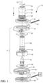
- the blood pump 10 includes a static structure or housing 12 which houses the components of the blood pump 10.
- the housing 12 includes a upper housing or first portion 14, a lower housing or second portion 16, and an inlet portion or inflow cannula 18 which includes an outer tube 18a and an inner tube 18b.
- the first portion 14 and the second portion 16 cooperatively define a volute shaped chamber 20 having a major longitudinal axis 22 extending through the first portion 14 and inflow cannula 18.
- the first stator 36 may be axially aligned with the rotor along axis 22 such that when a current is applied to the plurality of coils in the first stator 36, the electromagnetic forces generated by the first stator 36 rotate the rotor 32 and pump blood.
- a second stator 38 may be disposed within the second portion 16 downstream from the rotor 32. The second stator 38 may be configured to operate in conjunction with or independently of the first stator 36 to rotate the rotor 32.
- Electrical connectors 41 and 43 are provided on the first portion 14 and the second portion 16 respectively for connecting the coils to a common source of power such as a controller 39, shown connected to connector 41, but is also connected to the pump by connector 43.
- the controller 39 is arranged and configured to apply power to the coils of the pump to create a rotating magnetic field which spins rotor 32 around axis 22 in a predetermined first direction of rotation, such as the direction R indicated by the arrow in FIG. 1 , i.e., counterclockwise as seen from the upstream end of inflow cannula 18.
- the first direction may be clockwise.
- the controller 39 applies a first voltage waveform 44 to the first stator 36 and a second voltage waveform 46 to the second stator 38.
- Each of the first voltage waveform 44 and the second voltage waveform 46 provide power to rotate the impeller 32 independently of the other stator while the impeller is rotating after a startup sequence is initiated.
- the first voltage waveform 44 is equal to and symmetric with the second voltage waveform 46 such that the net axial force on the impeller 32 is zero.
- the first and second voltage waveforms define trapezoidal waveforms with sloped transitions applied at the same phase.
- the transition step of each waveform described herein refers to portions of the respective waveforms in which the voltage transitions from a positive voltage to a negative voltage polarity or vice-verse. As shown in FIG. 3 , the slope of the transition portions ("t 1 " or "t 2 ”) of the first and second voltage waveforms are equal, which creates a zero net axial force on the impeller 32.
Landscapes
- Health & Medical Sciences (AREA)
- Heart & Thoracic Surgery (AREA)
- Engineering & Computer Science (AREA)
- Cardiology (AREA)
- Biomedical Technology (AREA)
- Veterinary Medicine (AREA)
- Mechanical Engineering (AREA)
- Anesthesiology (AREA)
- Public Health (AREA)
- Hematology (AREA)
- Life Sciences & Earth Sciences (AREA)
- Animal Behavior & Ethology (AREA)
- General Health & Medical Sciences (AREA)
- Vascular Medicine (AREA)
- Physics & Mathematics (AREA)
- Fluid Mechanics (AREA)
- External Artificial Organs (AREA)
- Structures Of Non-Positive Displacement Pumps (AREA)
Claims (9)
- Dispositif de commande (39) pour une pompe à sang implantable (10) ayant un premier stator (36), un second stator (38) et un impulseur (32) disposée de manière mobile entre ceux-ci, le dispositif de commande comprenant :
un circuit de commande configuré pour :appliquer une première forme d'onde de tension (44) à la première phase au premier stator (36) pour générer un champ magnétique afin de faire tourner l'impulseur (32) pendant un premier laps de temps ;appliquer une seconde forme d'onde de tension (46) à une seconde phase décalée par rapport à la première phase au second stator (38) pour faire tourner l'impulseur (32) pendant le premier laps de temps, la seconde forme d'onde de tension (46) étant asymétrique par rapport à la première forme d'onde de tension (44). - Dispositif de commande (39) selon la revendication 1, dans lequel le circuit de commande est en outre configuré pour retarder de 60 degrés la seconde forme d'onde de tension d'application (46).
- Dispositif de commande (39) selon les revendications 1 ou 2, dans lequel la première forme d'onde de tension (44) est une onde carrée.
- Dispositif de commande (39) selon l'une quelconque des revendications 1-3, dans lequel la seconde forme d'onde de tension (46) est une onde carrée.
- Dispositif de commande (39) selon l'une quelconque des revendications 1-4, dans lequel la seconde forme d'onde de tension (46) est trapézoïdale.
- Dispositif de commande (39) selon l'une quelconque des revendications 1-5, dans lequel la première période de temps se produit pendant que l'impulseur (32) tourne.
- Dispositif de commande (39) selon l'une quelconque des revendications 1-6, dans lequel le circuit de commande est en outre configuré pour appliquer la première forme d'onde de tension (44) et la seconde forme d'onde de tension (46) pendant un second laps de temps différent du premier laps de temps, et dans lequel, pendant le second laps de temps, la première phase et la seconde phase sont identiques, et la première forme d'onde de tension (44) et la seconde forme d'onde de tension (46) sont symétriques.
- Dispositif de commande (39) selon l'une quelconque des revendications 1-6, dans lequel le circuit de commande est configuré de telle sorte que l'application de la première forme d'onde de tension (44) et de la seconde forme d'onde de tension (46) déplace l'impulseur (32) axialement.
- Dispositif de commande (39) selon la revendication 8, configuré pour fonctionner de telle sorte qu'un écart axial prédéterminé est maintenu entre l'impulseur (32) et le premier stator (36), et dans lequel le circuit de commande est configuré de telle sorte que l'application de la première forme d'onde de tension (44) et de la seconde forme d'onde de tension (46) augmente temporairement l'écart axial prédéterminé
Applications Claiming Priority (2)
| Application Number | Priority Date | Filing Date | Title |
|---|---|---|---|
| US201762594697P | 2017-12-05 | 2017-12-05 | |
| PCT/US2018/062431 WO2019112825A1 (fr) | 2017-12-05 | 2018-11-26 | Pompe à sang avec opération de rinçage de roue |
Publications (2)
| Publication Number | Publication Date |
|---|---|
| EP3720520A1 EP3720520A1 (fr) | 2020-10-14 |
| EP3720520B1 true EP3720520B1 (fr) | 2024-07-03 |
Family
ID=64664506
Family Applications (1)
| Application Number | Title | Priority Date | Filing Date |
|---|---|---|---|
| EP18816424.8A Active EP3720520B1 (fr) | 2017-12-05 | 2018-11-26 | Pompe à sang avec opération de rinçage de roue |
Country Status (4)
| Country | Link |
|---|---|
| US (2) | US11065434B2 (fr) |
| EP (1) | EP3720520B1 (fr) |
| CN (1) | CN111491677B (fr) |
| WO (1) | WO2019112825A1 (fr) |
Families Citing this family (33)
| Publication number | Priority date | Publication date | Assignee | Title |
|---|---|---|---|---|
| EP3720520B1 (fr) * | 2017-12-05 | 2024-07-03 | Heartware, Inc. | Pompe à sang avec opération de rinçage de roue |
| DE102018201030B4 (de) | 2018-01-24 | 2025-10-16 | Kardion Gmbh | Magnetkuppelelement mit magnetischer Lagerungsfunktion |
| DE102018207611A1 (de) | 2018-05-16 | 2019-11-21 | Kardion Gmbh | Rotorlagerungssystem |
| DE102018207575A1 (de) | 2018-05-16 | 2019-11-21 | Kardion Gmbh | Magnetische Stirndreh-Kupplung zur Übertragung von Drehmomenten |
| DE102018207594A1 (de) | 2018-05-16 | 2019-11-21 | Kardion Gmbh | Rotor, Magnetkupplungsvorrichtung, Elektromotor für ein Herzunterstützungssystem, Pumpeneinheit für ein Herzunterstützungssystem sowie Verfahren zum Herstellen eines Rotors |
| DE102018208550A1 (de) | 2018-05-30 | 2019-12-05 | Kardion Gmbh | Leitungsvorrichtung zum Leiten eines Blutstroms für ein Herzunterstützungssystem, Herzunterstützungssystem und Verfahren zum Herstellen einer Leitungsvorrichtung |
| DE102018208538A1 (de) | 2018-05-30 | 2019-12-05 | Kardion Gmbh | Intravasale Blutpumpe und Verfahren zur Herstellung von elektrischen Leiterbahnen |
| DE102018208541A1 (de) | 2018-05-30 | 2019-12-05 | Kardion Gmbh | Axialpumpe für ein Herzunterstützungssystem und Verfahren zum Herstellen einer Axialpumpe für ein Herzunterstützungssystem |
| DE102018208549A1 (de) | 2018-05-30 | 2019-12-05 | Kardion Gmbh | Elektronikmodul für ein Herzunterstützungssystem und Verfahren zum Herstellen eines Elektronikmoduls für ein Herzunterstützungssystem |
| DE102018208539A1 (de) | 2018-05-30 | 2019-12-05 | Kardion Gmbh | Motorgehäusemodul zum Abdichten eines Motorraums eines Motors eines Herzunterstützungssystems und Herzunterstützungssystem und Verfahren zum Montieren eines Herzunterstützungssystems |
| DE102018208899A1 (de) | 2018-06-06 | 2019-12-12 | Kardion Gmbh | Verfahren zum Ermitteln der Schallgeschwindigkeit in einem Fluid im Bereich eines implantierten, vaskulären Unterstützungssystems |
| DE102018208945A1 (de) | 2018-06-06 | 2019-12-12 | Kardion Gmbh | Analysevorrichtung und Verfahren zum Analysieren einer Viskosität eines Fluids |
| DE102018208862A1 (de) | 2018-06-06 | 2019-12-12 | Kardion Gmbh | Implantierbares, vaskuläres Unterstützungssystem |
| DE102018208892A1 (de) | 2018-06-06 | 2019-12-12 | Kardion Gmbh | Sensorkopfvorrichtung für ein minimalinvasives Herzunterstützungssystem und Verfahren zum Herstellen einer Sensorkopfvorrichtung für ein Herzunterstützungssystem |
| DE102018208933A1 (de) | 2018-06-06 | 2019-12-12 | Kardion Gmbh | Verfahren zur Bestimmung einer Strömungsgeschwindigkeit eines durch ein implantiertes, vaskuläres Unterstützungssystem strömenden Fluids |
| DE102018208936A1 (de) | 2018-06-06 | 2019-12-12 | Kardion Gmbh | Bestimmvorrichtung und Verfahren zum Bestimmen einer Viskosität eines Fluids |
| DE102018208870A1 (de) | 2018-06-06 | 2019-12-12 | Kardion Gmbh | Verfahren zur Bestimmung eines Fluid-Volumenstroms durch ein implantiertes, vaskuläres Unterstützungssystem |
| DE102018208913A1 (de) | 2018-06-06 | 2019-12-12 | Kardion Gmbh | Verfahren zum Betreiben eines implantierten, ventrikulären Unterstützungssystems |
| DE102018208931A1 (de) | 2018-06-06 | 2019-12-12 | Kardion Gmbh | Vorrichtung zum Bestimmen eines Herzzeitvolumens für ein Herzunterstützungssystem, Herzunterstützungssystem und Verfahren zum Bestimmen eines Herzzeitvolumens |
| DE102018208929A1 (de) | 2018-06-06 | 2019-12-12 | Kardion Gmbh | Verfahren zur Bestimmung einer Strömungsgeschwindigkeit eines durch ein implantiertes, vaskuläres Unterstützungssystem strömenden Fluids |
| DE102018208879A1 (de) | 2018-06-06 | 2020-01-30 | Kardion Gmbh | Verfahren zur Bestimmung eines Fluid-Gesamtvolumenstroms im Bereich eines implantierten, vaskuläres Unterstützungssystems |
| DE102018210058A1 (de) | 2018-06-21 | 2019-12-24 | Kardion Gmbh | Statorschaufelvorrichtung zur Strömungsführung eines aus einer Austrittsöffnung eines Herzunterstützungssystems ausströmenden Fluids, Herzunterstützungssystem mit Statorschaufelvorrichtung, Verfahren zum Betreiben einer Statorschaufelvorrichtung und Herstellverfahren |
| DE102018210076A1 (de) | 2018-06-21 | 2019-12-24 | Kardion Gmbh | Verfahren und Vorrichtung zum Erkennen eines Verschleißzustands eines Herzunterstützungssystems, Verfahren und Vorrichtung zum Betreiben eines Herzunterstützungssystems und Herzunterstützungssystem |
| DE102018211297A1 (de) | 2018-07-09 | 2020-01-09 | Kardion Gmbh | Herzunterstützungssystem und Verfahren zur Überwachung der Integrität einer Haltestruktur eines Herzunterstützungssystems |
| DE102018211328A1 (de) | 2018-07-10 | 2020-01-16 | Kardion Gmbh | Laufradgehäuse für ein implantierbares, vaskuläres Unterstützungssystem |
| DE102018211327A1 (de) | 2018-07-10 | 2020-01-16 | Kardion Gmbh | Laufrad für ein implantierbares, vaskuläres Unterstützungssystem |
| DE102018212153A1 (de) | 2018-07-20 | 2020-01-23 | Kardion Gmbh | Zulaufleitung für eine Pumpeneinheit eines Herzunterstützungssystems, Herzunterstützungssystem und Verfahren zum Herstellen einer Zulaufleitung für eine Pumpeneinheit eines Herzunterstützungssystems |
| AU2019320533B2 (en) | 2018-08-07 | 2024-11-21 | Kardion Gmbh | Bearing device for a cardiac support system, and method for flushing an intermediate space in a bearing device for a cardiac support system |
| DE102018213350A1 (de) | 2018-08-08 | 2020-02-13 | Kardion Gmbh | Vorrichtung und Verfahren zur Überwachung eines Gesundheitszustands des Patienten |
| US11318295B2 (en) * | 2019-02-28 | 2022-05-03 | Heartware, Inc. | HVAD rinse via a non-uniform thrust bearing gap |
| DE102020102474A1 (de) | 2020-01-31 | 2021-08-05 | Kardion Gmbh | Pumpe zum Fördern eines Fluids und Verfahren zum Herstellen einer Pumpe |
| CA3192451A1 (fr) | 2020-09-14 | 2022-03-17 | Johannes Bette | Pompe de support cardiovasculaire dotee d'un impulseur a zone d'ecoulement variable |
| JP2023550938A (ja) | 2020-11-20 | 2023-12-06 | カルディオン ゲーエムベーハー | ガイドワイヤ補助具付き機械的循環支持システム |
Family Cites Families (41)
| Publication number | Priority date | Publication date | Assignee | Title |
|---|---|---|---|---|
| US4944748A (en) * | 1986-10-12 | 1990-07-31 | Bramm Gunter W | Magnetically suspended and rotated rotor |
| US5078741A (en) * | 1986-10-12 | 1992-01-07 | Life Extenders Corporation | Magnetically suspended and rotated rotor |
| WO1987000360A1 (fr) * | 1985-06-29 | 1987-01-15 | Hartmut Griepentrog | Machine comportant un rotor a paliers magnetiques et une machine electrique a champ radial |
| US6808482B1 (en) * | 1994-04-15 | 2004-10-26 | Allegheny-Singer Research Institute | Blood pump device and method of producing |
| US5840070A (en) | 1996-02-20 | 1998-11-24 | Kriton Medical, Inc. | Sealless rotary blood pump |
| EP1019117B2 (fr) * | 1997-10-02 | 2015-03-18 | Micromed Technology, Inc. | Unité de contrôle pour système de pompage implantable |
| US6293901B1 (en) * | 1997-11-26 | 2001-09-25 | Vascor, Inc. | Magnetically suspended fluid pump and control system |
| US6264635B1 (en) * | 1998-12-03 | 2001-07-24 | Kriton Medical, Inc. | Active magnetic bearing system for blood pump |
| US6227817B1 (en) * | 1999-09-03 | 2001-05-08 | Magnetic Moments, Llc | Magnetically-suspended centrifugal blood pump |
| US20030164654A1 (en) * | 2002-02-25 | 2003-09-04 | Thaxton Edgar S. | Axially segmented permanent magnet synchronous machine with integrated magnetic bearings and active stator control of the axial degree-of-freedom |
| US20040241019A1 (en) | 2003-05-28 | 2004-12-02 | Michael Goldowsky | Passive non-contacting smart bearing suspension for turbo blood-pumps |
| DE10330434A1 (de) * | 2003-07-04 | 2005-02-03 | Jostra Ag | Zentrifugal-Pumpe |
| WO2005030296A2 (fr) * | 2003-09-25 | 2005-04-07 | Medforte Research Foundation | Pompe sanguine a debit axial presentant un impulseur stabilise radialement et axialement, magnetiquement suspendu |
| US8419609B2 (en) | 2005-10-05 | 2013-04-16 | Heartware Inc. | Impeller for a rotary ventricular assist device |
| EP3954901A1 (fr) | 2006-01-13 | 2022-02-16 | HeartWare, Inc. | Pompe sanguine rotative |
| DE102006036948A1 (de) * | 2006-08-06 | 2008-02-07 | Akdis, Mustafa, Dipl.-Ing. | Blutpumpe |
| US8152493B2 (en) * | 2007-04-30 | 2012-04-10 | Hearthware Inc. | Centrifugal rotary blood pump with impeller having a hydrodynamic thrust bearing surface |
| CN101868628B (zh) * | 2007-10-18 | 2015-08-19 | 克里夫兰诊所基金会 | 两级转子动力血泵 |
| CN102239334B (zh) * | 2008-12-08 | 2015-03-04 | 胸腔科技有限公司 | 离心式泵装置 |
| US8632449B2 (en) * | 2009-04-16 | 2014-01-21 | Bivacor Pty Ltd | Heart pump controller |
| JP5577506B2 (ja) * | 2010-09-14 | 2014-08-27 | ソーラテック コーポレイション | 遠心式ポンプ装置 |
| TWI402436B (zh) * | 2010-12-30 | 2013-07-21 | 私立中原大學 | 混合式軸向磁浮軸承及其工作方法與其轉動體結構 |
| EP2693609B1 (fr) * | 2011-03-28 | 2017-05-03 | Thoratec Corporation | Dispositif de rotation et d'entraînement, et dispositif de pompe centrifuge utilisant ce dispositif |
| EP4252823A3 (fr) * | 2012-08-15 | 2023-11-15 | Artio Medical, Inc. | Systèmes et procédés de pompe d'assistance circulatoire |
| US10857274B2 (en) * | 2012-11-06 | 2020-12-08 | Queen Mary University Of London | Mechanical circulatory support device with centrifugal impeller designed for implantation in the descending aorta |
| US9371826B2 (en) * | 2013-01-24 | 2016-06-21 | Thoratec Corporation | Impeller position compensation using field oriented control |
| US9556873B2 (en) * | 2013-02-27 | 2017-01-31 | Tc1 Llc | Startup sequence for centrifugal pump with levitated impeller |
| AU2014306398B2 (en) * | 2013-08-16 | 2019-01-31 | Cardiobionic Pty Ltd | Heart assist system and/or device |
| WO2015026711A1 (fr) * | 2013-08-19 | 2015-02-26 | Heartware, Inc. | Système de puissance sans fil multibande |
| CN103893849B (zh) * | 2014-04-15 | 2016-01-20 | 中南大学 | 一种大气隙磁力驱动的全植入式轴流式血泵及其控制方法 |
| US10030664B2 (en) | 2014-06-17 | 2018-07-24 | Ch Biomedical (Usa) Inc. | Centrifugal blood pump impeller and flow path |
| US20160166211A1 (en) * | 2014-12-02 | 2016-06-16 | Heartware, Inc. | Mean arterial pressure estimation |
| US9717832B2 (en) * | 2015-01-06 | 2017-08-01 | HeartWave, Inc. | Axial flow rotor with downstream bearing wash flow |
| WO2016130944A1 (fr) * | 2015-02-12 | 2016-08-18 | Thoratec Corporation | Système et procédé de commande de la position d'un rotor en lévitation |
| US10371152B2 (en) * | 2015-02-12 | 2019-08-06 | Tc1 Llc | Alternating pump gaps |
| ES2839081T3 (es) * | 2015-03-18 | 2021-07-05 | Abiomed Europe Gmbh | Bomba de sangre |
| EP3173109A1 (fr) * | 2015-11-30 | 2017-05-31 | Fundacja Rozwoju Kardiochirurgii Im. Prof. Zbigniewa Religi | Procédé de contrôle de la position de l'impulseur de pompe centrifuge d'assistance cardiaque |
| WO2017120453A1 (fr) * | 2016-01-06 | 2017-07-13 | Bivacor Inc. | Pompe cardiaque avec commande de position axiale de turbine |
| CN105477706B (zh) * | 2016-01-14 | 2018-01-26 | 山东大学 | 双定子混合支承人工心脏泵 |
| US10543302B2 (en) * | 2017-08-16 | 2020-01-28 | Heartware, Inc. | Map measurement on VAD patients with low pulsatility |
| EP3720520B1 (fr) * | 2017-12-05 | 2024-07-03 | Heartware, Inc. | Pompe à sang avec opération de rinçage de roue |
-
2018
- 2018-11-26 EP EP18816424.8A patent/EP3720520B1/fr active Active
- 2018-11-26 US US16/199,684 patent/US11065434B2/en active Active
- 2018-11-26 CN CN201880078562.4A patent/CN111491677B/zh active Active
- 2018-11-26 WO PCT/US2018/062431 patent/WO2019112825A1/fr not_active Ceased
-
2021
- 2021-06-24 US US17/356,704 patent/US11969588B2/en active Active
Also Published As
| Publication number | Publication date |
|---|---|
| CN111491677A (zh) | 2020-08-04 |
| US20190167874A1 (en) | 2019-06-06 |
| US11065434B2 (en) | 2021-07-20 |
| US20210322755A1 (en) | 2021-10-21 |
| WO2019112825A1 (fr) | 2019-06-13 |
| CN111491677B (zh) | 2023-12-01 |
| EP3720520A1 (fr) | 2020-10-14 |
| US11969588B2 (en) | 2024-04-30 |
Similar Documents
| Publication | Publication Date | Title |
|---|---|---|
| US11969588B2 (en) | Blood pump with impeller rinse operation | |
| EP3668561B1 (fr) | Traitement thérapeutique du sang par uv dans une pompe à sang | |
| EP3615103B1 (fr) | Élément céramique à potentiel de surface antithrombotique | |
| EP3930785B1 (fr) | Rincage de vad via un interstice de palier de butee non-uniforme | |
| US11648393B2 (en) | Implantable blood pump with thrombus diverter | |
| US11534596B2 (en) | Pulsatile blood pump via contraction with smart material | |
| EP3436106B1 (fr) | Pompe à sang à écoulement axial dotée d'un rotor décalé radialement | |
| WO2021141693A1 (fr) | Angle de palier de butée passif | |
| CN110997032A (zh) | 使用柔性电子传感器和发射器的血栓检测和去除 | |
| WO2006118600A2 (fr) | Pompe a flux axial, a larges ailettes et a rotors multiples | |
| US12156745B2 (en) | Detection of hypertension in LVAD patients using speed change | |
| EP3852832B1 (fr) | Procédé de démarrage d'une pompe à sang avec un défaut électrique |
Legal Events
| Date | Code | Title | Description |
|---|---|---|---|
| STAA | Information on the status of an ep patent application or granted ep patent |
Free format text: STATUS: UNKNOWN |
|
| STAA | Information on the status of an ep patent application or granted ep patent |
Free format text: STATUS: THE INTERNATIONAL PUBLICATION HAS BEEN MADE |
|
| PUAI | Public reference made under article 153(3) epc to a published international application that has entered the european phase |
Free format text: ORIGINAL CODE: 0009012 |
|
| STAA | Information on the status of an ep patent application or granted ep patent |
Free format text: STATUS: REQUEST FOR EXAMINATION WAS MADE |
|
| 17P | Request for examination filed |
Effective date: 20200622 |
|
| AK | Designated contracting states |
Kind code of ref document: A1 Designated state(s): AL AT BE BG CH CY CZ DE DK EE ES FI FR GB GR HR HU IE IS IT LI LT LU LV MC MK MT NL NO PL PT RO RS SE SI SK SM TR |
|
| AX | Request for extension of the european patent |
Extension state: BA ME |
|
| DAV | Request for validation of the european patent (deleted) | ||
| DAX | Request for extension of the european patent (deleted) | ||
| STAA | Information on the status of an ep patent application or granted ep patent |
Free format text: STATUS: EXAMINATION IS IN PROGRESS |
|
| 17Q | First examination report despatched |
Effective date: 20220412 |
|
| 17Q | First examination report despatched |
Effective date: 20220923 |
|
| REG | Reference to a national code |
Ref country code: DE Ref legal event code: R079 Free format text: PREVIOUS MAIN CLASS: A61M0001120000 Ipc: A61M0001000000 Ref country code: DE Ref legal event code: R079 Ref document number: 602018071369 Country of ref document: DE Free format text: PREVIOUS MAIN CLASS: A61M0001120000 Ipc: A61M0001000000 |
|
| GRAP | Despatch of communication of intention to grant a patent |
Free format text: ORIGINAL CODE: EPIDOSNIGR1 |
|
| STAA | Information on the status of an ep patent application or granted ep patent |
Free format text: STATUS: GRANT OF PATENT IS INTENDED |
|
| RIC1 | Information provided on ipc code assigned before grant |
Ipc: A61M 1/00 20060101AFI20240226BHEP |
|
| INTG | Intention to grant announced |
Effective date: 20240313 |
|
| GRAS | Grant fee paid |
Free format text: ORIGINAL CODE: EPIDOSNIGR3 |
|
| GRAA | (expected) grant |
Free format text: ORIGINAL CODE: 0009210 |
|
| STAA | Information on the status of an ep patent application or granted ep patent |
Free format text: STATUS: THE PATENT HAS BEEN GRANTED |
|
| AK | Designated contracting states |
Kind code of ref document: B1 Designated state(s): AL AT BE BG CH CY CZ DE DK EE ES FI FR GB GR HR HU IE IS IT LI LT LU LV MC MK MT NL NO PL PT RO RS SE SI SK SM TR |
|
| REG | Reference to a national code |
Ref country code: CH Ref legal event code: EP |
|
| REG | Reference to a national code |
Ref country code: DE Ref legal event code: R096 Ref document number: 602018071369 Country of ref document: DE |
|
| REG | Reference to a national code |
Ref country code: LT Ref legal event code: MG9D |
|
| REG | Reference to a national code |
Ref country code: NL Ref legal event code: MP Effective date: 20240703 |
|
| PG25 | Lapsed in a contracting state [announced via postgrant information from national office to epo] |
Ref country code: PT Free format text: LAPSE BECAUSE OF FAILURE TO SUBMIT A TRANSLATION OF THE DESCRIPTION OR TO PAY THE FEE WITHIN THE PRESCRIBED TIME-LIMIT Effective date: 20241104 |
|
| REG | Reference to a national code |
Ref country code: AT Ref legal event code: MK05 Ref document number: 1699142 Country of ref document: AT Kind code of ref document: T Effective date: 20240703 |
|
| PG25 | Lapsed in a contracting state [announced via postgrant information from national office to epo] |
Ref country code: NL Free format text: LAPSE BECAUSE OF FAILURE TO SUBMIT A TRANSLATION OF THE DESCRIPTION OR TO PAY THE FEE WITHIN THE PRESCRIBED TIME-LIMIT Effective date: 20240703 |
|
| PG25 | Lapsed in a contracting state [announced via postgrant information from national office to epo] |
Ref country code: PT Free format text: LAPSE BECAUSE OF FAILURE TO SUBMIT A TRANSLATION OF THE DESCRIPTION OR TO PAY THE FEE WITHIN THE PRESCRIBED TIME-LIMIT Effective date: 20241104 Ref country code: NL Free format text: LAPSE BECAUSE OF FAILURE TO SUBMIT A TRANSLATION OF THE DESCRIPTION OR TO PAY THE FEE WITHIN THE PRESCRIBED TIME-LIMIT Effective date: 20240703 |
|
| RAP2 | Party data changed (patent owner data changed or rights of a patent transferred) |
Owner name: BOSTON SCIENTIFIC SCIMED, INC. |
|
| PG25 | Lapsed in a contracting state [announced via postgrant information from national office to epo] |
Ref country code: NO Free format text: LAPSE BECAUSE OF FAILURE TO SUBMIT A TRANSLATION OF THE DESCRIPTION OR TO PAY THE FEE WITHIN THE PRESCRIBED TIME-LIMIT Effective date: 20241003 |
|
| PG25 | Lapsed in a contracting state [announced via postgrant information from national office to epo] |
Ref country code: FI Free format text: LAPSE BECAUSE OF FAILURE TO SUBMIT A TRANSLATION OF THE DESCRIPTION OR TO PAY THE FEE WITHIN THE PRESCRIBED TIME-LIMIT Effective date: 20240703 Ref country code: GR Free format text: LAPSE BECAUSE OF FAILURE TO SUBMIT A TRANSLATION OF THE DESCRIPTION OR TO PAY THE FEE WITHIN THE PRESCRIBED TIME-LIMIT Effective date: 20241004 Ref country code: PL Free format text: LAPSE BECAUSE OF FAILURE TO SUBMIT A TRANSLATION OF THE DESCRIPTION OR TO PAY THE FEE WITHIN THE PRESCRIBED TIME-LIMIT Effective date: 20240703 |
|
| PG25 | Lapsed in a contracting state [announced via postgrant information from national office to epo] |
Ref country code: BG Free format text: LAPSE BECAUSE OF FAILURE TO SUBMIT A TRANSLATION OF THE DESCRIPTION OR TO PAY THE FEE WITHIN THE PRESCRIBED TIME-LIMIT Effective date: 20240703 |
|
| PG25 | Lapsed in a contracting state [announced via postgrant information from national office to epo] |
Ref country code: LV Free format text: LAPSE BECAUSE OF FAILURE TO SUBMIT A TRANSLATION OF THE DESCRIPTION OR TO PAY THE FEE WITHIN THE PRESCRIBED TIME-LIMIT Effective date: 20240703 |
|
| PG25 | Lapsed in a contracting state [announced via postgrant information from national office to epo] |
Ref country code: IS Free format text: LAPSE BECAUSE OF FAILURE TO SUBMIT A TRANSLATION OF THE DESCRIPTION OR TO PAY THE FEE WITHIN THE PRESCRIBED TIME-LIMIT Effective date: 20241103 Ref country code: AT Free format text: LAPSE BECAUSE OF FAILURE TO SUBMIT A TRANSLATION OF THE DESCRIPTION OR TO PAY THE FEE WITHIN THE PRESCRIBED TIME-LIMIT Effective date: 20240703 |
|
| PG25 | Lapsed in a contracting state [announced via postgrant information from national office to epo] |
Ref country code: HR Free format text: LAPSE BECAUSE OF FAILURE TO SUBMIT A TRANSLATION OF THE DESCRIPTION OR TO PAY THE FEE WITHIN THE PRESCRIBED TIME-LIMIT Effective date: 20240703 Ref country code: CZ Free format text: LAPSE BECAUSE OF FAILURE TO SUBMIT A TRANSLATION OF THE DESCRIPTION OR TO PAY THE FEE WITHIN THE PRESCRIBED TIME-LIMIT Effective date: 20240703 |
|
| PG25 | Lapsed in a contracting state [announced via postgrant information from national office to epo] |
Ref country code: RS Free format text: LAPSE BECAUSE OF FAILURE TO SUBMIT A TRANSLATION OF THE DESCRIPTION OR TO PAY THE FEE WITHIN THE PRESCRIBED TIME-LIMIT Effective date: 20241003 Ref country code: ES Free format text: LAPSE BECAUSE OF FAILURE TO SUBMIT A TRANSLATION OF THE DESCRIPTION OR TO PAY THE FEE WITHIN THE PRESCRIBED TIME-LIMIT Effective date: 20240703 |
|
| PG25 | Lapsed in a contracting state [announced via postgrant information from national office to epo] |
Ref country code: RS Free format text: LAPSE BECAUSE OF FAILURE TO SUBMIT A TRANSLATION OF THE DESCRIPTION OR TO PAY THE FEE WITHIN THE PRESCRIBED TIME-LIMIT Effective date: 20241003 Ref country code: PL Free format text: LAPSE BECAUSE OF FAILURE TO SUBMIT A TRANSLATION OF THE DESCRIPTION OR TO PAY THE FEE WITHIN THE PRESCRIBED TIME-LIMIT Effective date: 20240703 Ref country code: NO Free format text: LAPSE BECAUSE OF FAILURE TO SUBMIT A TRANSLATION OF THE DESCRIPTION OR TO PAY THE FEE WITHIN THE PRESCRIBED TIME-LIMIT Effective date: 20241003 Ref country code: LV Free format text: LAPSE BECAUSE OF FAILURE TO SUBMIT A TRANSLATION OF THE DESCRIPTION OR TO PAY THE FEE WITHIN THE PRESCRIBED TIME-LIMIT Effective date: 20240703 Ref country code: IS Free format text: LAPSE BECAUSE OF FAILURE TO SUBMIT A TRANSLATION OF THE DESCRIPTION OR TO PAY THE FEE WITHIN THE PRESCRIBED TIME-LIMIT Effective date: 20241103 Ref country code: HR Free format text: LAPSE BECAUSE OF FAILURE TO SUBMIT A TRANSLATION OF THE DESCRIPTION OR TO PAY THE FEE WITHIN THE PRESCRIBED TIME-LIMIT Effective date: 20240703 Ref country code: GR Free format text: LAPSE BECAUSE OF FAILURE TO SUBMIT A TRANSLATION OF THE DESCRIPTION OR TO PAY THE FEE WITHIN THE PRESCRIBED TIME-LIMIT Effective date: 20241004 Ref country code: FI Free format text: LAPSE BECAUSE OF FAILURE TO SUBMIT A TRANSLATION OF THE DESCRIPTION OR TO PAY THE FEE WITHIN THE PRESCRIBED TIME-LIMIT Effective date: 20240703 Ref country code: ES Free format text: LAPSE BECAUSE OF FAILURE TO SUBMIT A TRANSLATION OF THE DESCRIPTION OR TO PAY THE FEE WITHIN THE PRESCRIBED TIME-LIMIT Effective date: 20240703 Ref country code: CZ Free format text: LAPSE BECAUSE OF FAILURE TO SUBMIT A TRANSLATION OF THE DESCRIPTION OR TO PAY THE FEE WITHIN THE PRESCRIBED TIME-LIMIT Effective date: 20240703 Ref country code: BG Free format text: LAPSE BECAUSE OF FAILURE TO SUBMIT A TRANSLATION OF THE DESCRIPTION OR TO PAY THE FEE WITHIN THE PRESCRIBED TIME-LIMIT Effective date: 20240703 Ref country code: AT Free format text: LAPSE BECAUSE OF FAILURE TO SUBMIT A TRANSLATION OF THE DESCRIPTION OR TO PAY THE FEE WITHIN THE PRESCRIBED TIME-LIMIT Effective date: 20240703 |
|
| REG | Reference to a national code |
Ref country code: DE Ref legal event code: R097 Ref document number: 602018071369 Country of ref document: DE |
|
| PG25 | Lapsed in a contracting state [announced via postgrant information from national office to epo] |
Ref country code: SM Free format text: LAPSE BECAUSE OF FAILURE TO SUBMIT A TRANSLATION OF THE DESCRIPTION OR TO PAY THE FEE WITHIN THE PRESCRIBED TIME-LIMIT Effective date: 20240703 Ref country code: RO Free format text: LAPSE BECAUSE OF FAILURE TO SUBMIT A TRANSLATION OF THE DESCRIPTION OR TO PAY THE FEE WITHIN THE PRESCRIBED TIME-LIMIT Effective date: 20240703 Ref country code: DK Free format text: LAPSE BECAUSE OF FAILURE TO SUBMIT A TRANSLATION OF THE DESCRIPTION OR TO PAY THE FEE WITHIN THE PRESCRIBED TIME-LIMIT Effective date: 20240703 |
|
| PG25 | Lapsed in a contracting state [announced via postgrant information from national office to epo] |
Ref country code: EE Free format text: LAPSE BECAUSE OF FAILURE TO SUBMIT A TRANSLATION OF THE DESCRIPTION OR TO PAY THE FEE WITHIN THE PRESCRIBED TIME-LIMIT Effective date: 20240703 |
|
| PG25 | Lapsed in a contracting state [announced via postgrant information from national office to epo] |
Ref country code: SK Free format text: LAPSE BECAUSE OF FAILURE TO SUBMIT A TRANSLATION OF THE DESCRIPTION OR TO PAY THE FEE WITHIN THE PRESCRIBED TIME-LIMIT Effective date: 20240703 Ref country code: IT Free format text: LAPSE BECAUSE OF FAILURE TO SUBMIT A TRANSLATION OF THE DESCRIPTION OR TO PAY THE FEE WITHIN THE PRESCRIBED TIME-LIMIT Effective date: 20240703 |
|
| PLBE | No opposition filed within time limit |
Free format text: ORIGINAL CODE: 0009261 |
|
| STAA | Information on the status of an ep patent application or granted ep patent |
Free format text: STATUS: NO OPPOSITION FILED WITHIN TIME LIMIT |
|
| 26N | No opposition filed |
Effective date: 20250404 |
|
| REG | Reference to a national code |
Ref country code: CH Ref legal event code: PL |
|
| PG25 | Lapsed in a contracting state [announced via postgrant information from national office to epo] |
Ref country code: MC Free format text: LAPSE BECAUSE OF FAILURE TO SUBMIT A TRANSLATION OF THE DESCRIPTION OR TO PAY THE FEE WITHIN THE PRESCRIBED TIME-LIMIT Effective date: 20240703 |
|
| PG25 | Lapsed in a contracting state [announced via postgrant information from national office to epo] |
Ref country code: LU Free format text: LAPSE BECAUSE OF NON-PAYMENT OF DUE FEES Effective date: 20241126 |
|
| REG | Reference to a national code |
Ref country code: CH Ref legal event code: PL |
|
| GBPC | Gb: european patent ceased through non-payment of renewal fee |
Effective date: 20241126 |
|
| PG25 | Lapsed in a contracting state [announced via postgrant information from national office to epo] |
Ref country code: CH Free format text: LAPSE BECAUSE OF NON-PAYMENT OF DUE FEES Effective date: 20241130 |
|
| REG | Reference to a national code |
Ref country code: BE Ref legal event code: MM Effective date: 20241130 |
|
| PG25 | Lapsed in a contracting state [announced via postgrant information from national office to epo] |
Ref country code: SE Free format text: LAPSE BECAUSE OF FAILURE TO SUBMIT A TRANSLATION OF THE DESCRIPTION OR TO PAY THE FEE WITHIN THE PRESCRIBED TIME-LIMIT Effective date: 20240703 |
|
| PG25 | Lapsed in a contracting state [announced via postgrant information from national office to epo] |
Ref country code: GB Free format text: LAPSE BECAUSE OF NON-PAYMENT OF DUE FEES Effective date: 20241126 Ref country code: BE Free format text: LAPSE BECAUSE OF NON-PAYMENT OF DUE FEES Effective date: 20241130 |
|
| PG25 | Lapsed in a contracting state [announced via postgrant information from national office to epo] |
Ref country code: FR Free format text: LAPSE BECAUSE OF NON-PAYMENT OF DUE FEES Effective date: 20241130 |
|
| PG25 | Lapsed in a contracting state [announced via postgrant information from national office to epo] |
Ref country code: IE Free format text: LAPSE BECAUSE OF NON-PAYMENT OF DUE FEES Effective date: 20241126 |
|
| PGFP | Annual fee paid to national office [announced via postgrant information from national office to epo] |
Ref country code: DE Payment date: 20251022 Year of fee payment: 8 |
|
| PG25 | Lapsed in a contracting state [announced via postgrant information from national office to epo] |
Ref country code: HU Free format text: LAPSE BECAUSE OF FAILURE TO SUBMIT A TRANSLATION OF THE DESCRIPTION OR TO PAY THE FEE WITHIN THE PRESCRIBED TIME-LIMIT; INVALID AB INITIO Effective date: 20181126 |
|
| PG25 | Lapsed in a contracting state [announced via postgrant information from national office to epo] |
Ref country code: CY Free format text: LAPSE BECAUSE OF FAILURE TO SUBMIT A TRANSLATION OF THE DESCRIPTION OR TO PAY THE FEE WITHIN THE PRESCRIBED TIME-LIMIT; INVALID AB INITIO Effective date: 20181126 |