EP1481777A2 - Dispositif de sortie de rouleaux pour une machine de coupe - Google Patents
Dispositif de sortie de rouleaux pour une machine de coupe Download PDFInfo
- Publication number
- EP1481777A2 EP1481777A2 EP04008724A EP04008724A EP1481777A2 EP 1481777 A2 EP1481777 A2 EP 1481777A2 EP 04008724 A EP04008724 A EP 04008724A EP 04008724 A EP04008724 A EP 04008724A EP 1481777 A2 EP1481777 A2 EP 1481777A2
- Authority
- EP
- European Patent Office
- Prior art keywords
- exit assembly
- roll
- roll exit
- chain
- cutting
- Prior art date
- Legal status (The legal status is an assumption and is not a legal conclusion. Google has not performed a legal analysis and makes no representation as to the accuracy of the status listed.)
- Withdrawn
Links
Images




Classifications
-
- B—PERFORMING OPERATIONS; TRANSPORTING
- B26—HAND CUTTING TOOLS; CUTTING; SEVERING
- B26D—CUTTING; DETAILS COMMON TO MACHINES FOR PERFORATING, PUNCHING, CUTTING-OUT, STAMPING-OUT OR SEVERING
- B26D7/00—Details of apparatus for cutting, cutting-out, stamping-out, punching, perforating, or severing by means other than cutting
- B26D7/06—Arrangements for feeding or delivering work of other than sheet, web, or filamentary form
- B26D7/0625—Arrangements for feeding or delivering work of other than sheet, web, or filamentary form by endless conveyors, e.g. belts
-
- B—PERFORMING OPERATIONS; TRANSPORTING
- B26—HAND CUTTING TOOLS; CUTTING; SEVERING
- B26D—CUTTING; DETAILS COMMON TO MACHINES FOR PERFORATING, PUNCHING, CUTTING-OUT, STAMPING-OUT OR SEVERING
- B26D7/00—Details of apparatus for cutting, cutting-out, stamping-out, punching, perforating, or severing by means other than cutting
- B26D7/01—Means for holding or positioning work
- B26D2007/013—Means for holding or positioning work the work being tubes, rods or logs
-
- B—PERFORMING OPERATIONS; TRANSPORTING
- B26—HAND CUTTING TOOLS; CUTTING; SEVERING
- B26D—CUTTING; DETAILS COMMON TO MACHINES FOR PERFORATING, PUNCHING, CUTTING-OUT, STAMPING-OUT OR SEVERING
- B26D2210/00—Machines or methods used for cutting special materials
- B26D2210/11—Machines or methods used for cutting special materials for cutting web rolls
Definitions
- the present invention relates to a roll exit assembly for a cutting off machine for the transverse cutting of rolls of sheet material, such as paper, starting from large-sized logs.
- the roll exit assembly serves to remove cut rolls from the cutting area.
- the log of paper to be cut is made to advance on the cutting off machine bench by means of a pusher towards a cutting disc, as described in European patent application EP0970784 in the name of the same applicant.
- the advancement of the log, under the action of the pusher pushes the cut roll onto a roll discharge belt whilst the trimming or end waste is pushed directly by the pusher.
- FIG. 1 illustrates a roll exit assembly 101 according to the prior art destined to be disposed downstream of a conveying bed 102 of a cutting off machine.
- rolls 103 of sheet material obtained by transverse cutting of a log, are fed toward the roll exit assembly 101 by means of a pusher 104 moved along the conveying bed 102 of the cutting off machine.
- the roll exit assembly 101 comprises a belt conveyor having two flat belts 105 and two belts 106 with a circular section.
- the flat belts 105 allow conveying of rolls in a vertical or raised position (not shown in Figures 1 and 2), that is to say with the axis of the roll at right angles to the conveying surface, whilst the belts 106 with a circular section, as shown in Figures 1 and 2, allow conveying of rolls 103 in a horizontal or lying position, that is to say with the axis of the roll parallel to the conveying surface.
- Said roll exit assembly 101 according to the prior art presents many drawbacks.
- the distance between the two circular section belts 106 is fixed, with the consequent limitation of the minimum and maximum diameters of the roll 103 to be conveyed, according to the distance between said belts. In fact, small diameter rolls sink too deep between the belts, whilst large diameter rolls are not gripped adequately.
- the width of the pusher 104 is limited by the distance between the two circular section belts 106 and this does not allow an adequate surface for pushing and pressing the log, especially in the case of large diameter logs.
- the end trimmings of the rolls with a high diameter/height (transverse measurement/axial measurement) ratio can rotate around the pusher 104 in the cutting area because of the friction between the log and the pressers (elements for blocking the log in the cutting area) during advancement of the log and/or because of the stress exerted by the cutting disk on the log during cutting.
- a height difference is generated between the log on the conveying bench 102 of the cutting off machine and the roll 103 on the roll exit assembly 101.
- the difference varies with the diameter of the roll and will be greater for small diameter rolls and smaller for large diameter rolls.
- the object of the present invention is to eliminate the drawbacks of the prior art by providing a roll exit assembly for a cutting off machine that is versatile and able to work with rolls of different diameters and formats.
- Another object of the present invention is to provide a roll exit assembly that is highly reliable and able to avoid risks of jamming of the machine.
- Yet another object of the present invention is to provide a roll exit assembly that is able to allow continuous high-speed production, without the need to stop components of the machine.
- the roll exit assembly comprises a conveyor consisting of two chains, belts or other conveying means which may support inserts of aluminium, Teflon or other material, of a suitable shape to grip the roll in a vertical or in a horizontal position.
- the chains are mounted on supports which can translate along a straight line, so as to keep constant the angle formed between the contact surfaces of the inserts of the two chains and to adapt the gripping width according to the diameter of the roll.
- the two chains thus form an ideal V-shaped support to accommodate the roll.
- the angle of opening of this V-shaped support is identical to that of the support bench of the cutting off machine. Thus, a height difference between the log on the bench and the roll on the exit assembly is avoided.
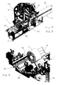
- FIG. 3 illustrates partially a cutting off machine, indicated as a whole with reference numeral 10.
- the cutting off machine 10 comprises a conveying bench 2, a cutting assembly 20 and a roll exit assembly 1.
- a log 30 of large length is conveyed on the conveying bench 2 towards the cutting assembly 20.
- the cutting assembly 20 comprises an arm 21 supporting a rotating disc 22 to perform the transverse cutting of the log 30 into rolls of smaller length.
- the roll 3 obtained by cutting the log 30 is pushed, by means of pushers 4, towards the roll exit assembly 1 which, by means of a conveying system 50, is responsible for conveying the rolls 3 towards roll discharge means. Movement of the pushers 4 takes place by means of a chain transmission in a per se known manner.
- the roll exit assembly 1 comprises a base frame 40 supported by feet 41 and disposed downstream of the cutting assembly 20.
- the base frame 40 supports the conveying system 50 and a conveyor belt 42 disposed downstream of the conveying system 50 to allow the discharge of the rolls 3 from the cutting off machine 10.
- the conveying system 50 comprises a support frame 51 to be mounted fixedly to the base frame 40.
- the support frame 51 On the sides of the support frame 51 there are provided two transmission track chains 60, disposed longitudinally and parallel to each other.
- conveying and drive transmission means such as belts and the like-able to support the cut rolls can be provided instead of the chains 60.
- Each chain 60 is supported by two pinions 62 and 63.
- the first pinion 62 is shrunk on a shaft mounted idly in a plate 66 carrying the chain 60.
- the second pinion 63 is shrunk on a drive shaft 64 set in rotation by an electric motor 65 disposed beyond the chain-carrying plate 66.
- each insert 61 has, towards the outside, a first face 61a substantially parallel with respect to a plane passing through the axes of rotation of the pinions 62 and 63 and a second face 61b substantially oblique with respect to said plane passing through the axes of rotation of the pinions 62 and 63.
- the support frame 51 has on each side a pair of support brackets 52 disposed obliquely with respect to a horizontal plane and converging with each other.
- the chain-carrying plates 66 are mounted on the respective support brackets 52 of the frame 51.
- the flat faces 61a of the inserts 61 of the chains are disposed obliquely with respect to a horizontal plane and diverge from each other, so as to form a substantially V-shaped seat able to receive the rolls 3 in a horizontal position.
- the oblique faces 61b of the inserts are disposed along a plane substantially parallel to the horizontal plane to receive the edges of a roll disposed vertically.
- the support frame 51 has a fixed structure comprising two sides 54 connected to a front crossbar 57.
- Two rear crossbars 58 are connected to the respective sides 54.
- two rods 59 connect the respective rear crossbars 58 to the front crossbar 57.
- Each movable structure consists of two support brackets 52, of an abutment plate 53 and of two slides or shoes 55.
- the shoes 55 are mounted slidably in a pair of grooved guides 56 integral with the front crossbar 57 and with the rear crossbars 58 of the support frame 51. In this manner each abutment plate 53 is maintained parallel to the respective side 54.
- the grooved guides 56 are substantially oblique with respect to a horizontal plane.
- each side 54 there is mounted a handwheel 70 which sets in rotation a screw 71 which passes through the respective side 54 to engage in a nut-screw formed in the abutment plate 53 of the mobile structure.
- the screw 71 which screws into the nut-screw of the abutment plate 53 is set in rotation.
- the shoes 55 which are integral with the abutment plate 53, slide linearly in the respective guides 56.
- the support brackets 52 move along a trajectory imposed by the guides 56.
- the chain-carrying plates 66 are integral with the respective pairs of brackets 52, by operating the handwheels 70 the distance between the chains 60 can be adjusted so as to adapt the conveying system 50 to the different diameters of the rolls 3 to be conveyed. With this system rolls 3 with diameters ranging from 90 mm to 350 mm can be conveyed.
- the movement of the chain-carrying plates 66 is synchronised.
- a pulley 73 which draws a respective belt 74 into rotation is shrunk on the shank of each screw 71.
- the belt 74 in turn sets in rotation another pulley 75 provided at the end of a synchronisation shaft 76.
- a gear 77 which meshes with a corresponding gear 77 or with an universal joint of the other synchronisation shaft 76.
- an automatic adjustment system such as an electric motor that sets the screw 71 in rotation could be provided, or an actuator that pushes the mobile structure could be provided in place of the screw and nut-screw system.
- the motors 65 that set the respective chains 60 in motion are synchronised with each other by means of a suitable inverter actuator, so as to allow synchronous rotation of the chains 60.
- a single motor and drive transmission means to transmit the drive to both chains 60 can be provided instead of the two motors 65.
- the speed of advancement of the chains 60 is controlled so as to be greater than the speed of advancement of the pushers 4 to allow a rapid removal of the rolls 3 from the area of rotation of the pushers 4.
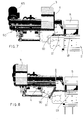
- the bench for conveying rolls 2 leaving the cutting assembly 20 has a cradle-shaped support guide 8 obtained by means of suitably inclined metal plates.
- the chains 60 are adjusted in position, so that the front face of the inserts 61 is kept in register with and substantially parallel to the plane of the guide metal plates 8. In this manner the passage of the roll 3 from the guide 8 of the conveying bench to the chains 60 of the conveying system 50 of the exit assembly 1 is facilitated.
- the conveying system 50 of the roll exit assembly 1 is particularly suitable for also conveying rolls 3 in the vertical position, that is to say with the axis of the roll at right angles to the conveying surface.
- the edges of the roll 3 rest on the oblique faces 61b of the inserts 61 of the chains.
- the pusher 4 consists of a plate supported by a flange 90 mounted on a carriage 91 slidable in guides 93 of the conveying bench.
- the front end of the conveying bench 2 ends in register with the front end of the cradle-shaped guide 8. Therefore the pusher 4, when it reaches the front end of the conveying bench 2, that is to say at the end of its working stroke, pushes the roll 3 between the chains 60 of the roll exit assembly to begin rotation and its return stroke.
- the pushing plate of the pusher 4 can be chosen sufficiently wide to be able to pass in the space between the two chains 60. In this manner a larger surface for pushing the log 30 is ensured.
- the invention is not limited to said embodiment.
- the inserts 61 are optional and can therefore be omitted.
- the chains 60 can be replaced by other conveying means, such as, for example, belts and the like.
Landscapes
- Life Sciences & Earth Sciences (AREA)
- Forests & Forestry (AREA)
- Engineering & Computer Science (AREA)
- Mechanical Engineering (AREA)
- Delivering By Means Of Belts And Rollers (AREA)
Applications Claiming Priority (2)
| Application Number | Priority Date | Filing Date | Title |
|---|---|---|---|
| ITMI20031050 | 2003-05-26 | ||
| IT001050A ITMI20031050A1 (it) | 2003-05-26 | 2003-05-26 | Gruppo di uscita rotoli per macchina troncatrice |
Publications (2)
| Publication Number | Publication Date |
|---|---|
| EP1481777A2 true EP1481777A2 (fr) | 2004-12-01 |
| EP1481777A3 EP1481777A3 (fr) | 2005-06-08 |
Family
ID=30131080
Family Applications (1)
| Application Number | Title | Priority Date | Filing Date |
|---|---|---|---|
| EP04008724A Withdrawn EP1481777A3 (fr) | 2003-05-26 | 2004-04-13 | Dispositif de sortie de rouleaux pour une machine de coupe |
Country Status (2)
| Country | Link |
|---|---|
| EP (1) | EP1481777A3 (fr) |
| IT (1) | ITMI20031050A1 (fr) |
Cited By (9)
| Publication number | Priority date | Publication date | Assignee | Title |
|---|---|---|---|---|
| FR2917662A1 (fr) * | 2007-06-21 | 2008-12-26 | Eberle Soc Par Actions Simplif | Dispositif de support et d'entrainement de tubes, en particulier de tubes de faible epaisseur de paroi, en fin d'enroulement et pendant la coupe a la volee |
| CN106965237A (zh) * | 2017-05-12 | 2017-07-21 | 北塘区军之印纸品加工厂 | 一种纸卷加工用剪切辅助装置 |
| ITUA20163298A1 (it) * | 2016-05-10 | 2017-11-10 | Paper Converting Machine Company Italia S P A | Macchina troncatrice e metodo di taglio di rotoli di materiale in foglio |
| CN109129026A (zh) * | 2018-10-24 | 2019-01-04 | 深圳格瑞克机械有限公司 | 笔杆自动切削机 |
| CN112092031A (zh) * | 2020-07-17 | 2020-12-18 | 保定市碧柔卫生用品有限公司 | 一种卷筒卫生纸切割装置 |
| CN112623329A (zh) * | 2020-12-10 | 2021-04-09 | 杭州中亚机械股份有限公司 | 一种用于灌装生产线的插棒装置 |
| CN116079806A (zh) * | 2023-04-07 | 2023-05-09 | 颐中(潍坊)实业有限公司 | 一种双轴卷筒纸可调式分切机 |
| CN116160100A (zh) * | 2023-04-21 | 2023-05-26 | 中建材(合肥)钢构科技有限公司 | 一种钢管自动上料的等离子切割装置 |
| CN117260840A (zh) * | 2023-10-08 | 2023-12-22 | 亿得宝科技发展有限公司 | 自动对点识别式辊压滚刀裁切装置及其自动对点识别方法 |
Families Citing this family (4)
| Publication number | Priority date | Publication date | Assignee | Title |
|---|---|---|---|---|
| CN108515727B (zh) * | 2018-03-28 | 2019-07-19 | 江苏南江智能装备股份有限公司 | 一种链条式纸质手提成型机及手提成型方法 |
| CN109129663A (zh) * | 2018-09-27 | 2019-01-04 | 盐城市华森机械有限公司 | 一种砂纸自动冲切机 |
| CN117656141B (zh) * | 2024-02-01 | 2024-04-05 | 青州金青云新材料有限公司 | 一种镀铝纸裁剪装置 |
| CN120481091B (zh) * | 2025-06-16 | 2025-12-05 | 青岛山岛建材有限公司 | 一种适用于大型石材的降尘切割设备 |
Family Cites Families (5)
| Publication number | Priority date | Publication date | Assignee | Title |
|---|---|---|---|---|
| US4265361A (en) * | 1979-10-10 | 1981-05-05 | American Can Company | Apparatus for handling wound rolls of fibrous webs |
| IT1198571B (it) * | 1983-03-18 | 1988-12-21 | Lucchese Finanz | Attrezzatura per eliminare gli estremi inutilizzabili (rifili) di bastoni di carta tagliati per la formazione di rotolini per carta igienica ed altro |
| IT1259683B (it) * | 1992-09-28 | 1996-03-25 | Perini Fabio Spa | Congegno eliminatore di rifili, associato ad una macchina troncatrice per la formazione di rotolini di carta igienica o simili |
| ATE240191T1 (de) * | 1998-07-07 | 2003-05-15 | Italconverting S P A | Vorrichtung zur automatischen entfernung von abfällen in der herstellung von papierrollen |
| ITFI20020102A1 (it) * | 2002-06-13 | 2003-12-15 | Perini Fabio Spa | Dispositivo per l'eliminazione di rifili di taglio di un rotolo od altro |
-
2003
- 2003-05-26 IT IT001050A patent/ITMI20031050A1/it unknown
-
2004
- 2004-04-13 EP EP04008724A patent/EP1481777A3/fr not_active Withdrawn
Cited By (12)
| Publication number | Priority date | Publication date | Assignee | Title |
|---|---|---|---|---|
| FR2917662A1 (fr) * | 2007-06-21 | 2008-12-26 | Eberle Soc Par Actions Simplif | Dispositif de support et d'entrainement de tubes, en particulier de tubes de faible epaisseur de paroi, en fin d'enroulement et pendant la coupe a la volee |
| ITUA20163298A1 (it) * | 2016-05-10 | 2017-11-10 | Paper Converting Machine Company Italia S P A | Macchina troncatrice e metodo di taglio di rotoli di materiale in foglio |
| EP3243612A1 (fr) * | 2016-05-10 | 2017-11-15 | Paper Converting Machine Company Italia S.p.A. | Machine de découpe et procédé de découpage de rouleaux de matériau en feuille |
| CN106965237A (zh) * | 2017-05-12 | 2017-07-21 | 北塘区军之印纸品加工厂 | 一种纸卷加工用剪切辅助装置 |
| CN109129026A (zh) * | 2018-10-24 | 2019-01-04 | 深圳格瑞克机械有限公司 | 笔杆自动切削机 |
| CN112092031A (zh) * | 2020-07-17 | 2020-12-18 | 保定市碧柔卫生用品有限公司 | 一种卷筒卫生纸切割装置 |
| CN112623329A (zh) * | 2020-12-10 | 2021-04-09 | 杭州中亚机械股份有限公司 | 一种用于灌装生产线的插棒装置 |
| CN112623329B (zh) * | 2020-12-10 | 2023-11-14 | 杭州中亚机械股份有限公司 | 一种用于灌装生产线的插棒装置 |
| CN116079806A (zh) * | 2023-04-07 | 2023-05-09 | 颐中(潍坊)实业有限公司 | 一种双轴卷筒纸可调式分切机 |
| CN116160100A (zh) * | 2023-04-21 | 2023-05-26 | 中建材(合肥)钢构科技有限公司 | 一种钢管自动上料的等离子切割装置 |
| CN116160100B (zh) * | 2023-04-21 | 2023-06-27 | 中建材(合肥)钢构科技有限公司 | 一种钢管自动上料的等离子切割装置 |
| CN117260840A (zh) * | 2023-10-08 | 2023-12-22 | 亿得宝科技发展有限公司 | 自动对点识别式辊压滚刀裁切装置及其自动对点识别方法 |
Also Published As
| Publication number | Publication date |
|---|---|
| EP1481777A3 (fr) | 2005-06-08 |
| ITMI20031050A0 (it) | 2003-05-26 |
| ITMI20031050A1 (it) | 2004-11-27 |
Similar Documents
| Publication | Publication Date | Title |
|---|---|---|
| EP1481777A2 (fr) | Dispositif de sortie de rouleaux pour une machine de coupe | |
| WO2015194983A1 (fr) | Machine comportant un couteau à ruban sans fin de coupe de panneaux éponge en morceaux | |
| JP4383573B2 (ja) | 仮とじ本、雑誌又は書籍のような印刷物の自動断裁用断裁機 | |
| JP2017052091A (ja) | 長尺状の被切断物のスライス切断方法、及びその装置、長尺パイプ材のv溝スライス切断方法、及びその装置、並びに可搬式スライス切断機 | |
| CN215698420U (zh) | 一种板材加工用连续剪板机 | |
| US4750254A (en) | Continuously operating one-sided formatting and edge shaping machine | |
| KR101011716B1 (ko) | 고속 슬라이서의 절편 스테킹장치 | |
| CN116140694B (zh) | 一种用于铝板剪切的输送设备 | |
| CN117548727A (zh) | 金属板料剪切装置 | |
| CN116475297A (zh) | 料带裁切设备 | |
| CN212598567U (zh) | 一种切断机的送料装置 | |
| CN118528345B (zh) | 一种塑料件切割装置 | |
| JP4463281B2 (ja) | 帯状板処理設備 | |
| CN113510289A (zh) | 一种钢带用裁剪装置 | |
| US6067884A (en) | Part cutting machine | |
| ITFI20060064A1 (it) | Segatrice a nastro a ponte mobile per il taglio assiale di barre o tubi metallici | |
| CN115709822B (zh) | 一种板材用覆膜切膜机器 | |
| CN200977614Y (zh) | 具有自动翻料装置的管、棒除毛边机 | |
| JP2662375B2 (ja) | 板金加工機 | |
| CA2687357A1 (fr) | Dispositif de transport pour une installation d'aboutage par entures multiples | |
| CN216938626U (zh) | 用于钢带加工线的剪切装置 | |
| CN105538397B (zh) | 一种分切机的减速机构 | |
| CN223989801U (zh) | 一种纸箱加工结构 | |
| CN215395530U (zh) | 产品加工自动分切机 | |
| CN115251125B (zh) | 一种肉类产品的切片装置 |
Legal Events
| Date | Code | Title | Description |
|---|---|---|---|
| PUAI | Public reference made under article 153(3) epc to a published international application that has entered the european phase |
Free format text: ORIGINAL CODE: 0009012 |
|
| AK | Designated contracting states |
Kind code of ref document: A2 Designated state(s): AT BE BG CH CY CZ DE DK EE ES FI FR GB GR HU IE IT LI LU MC NL PL PT RO SE SI SK TR |
|
| AX | Request for extension of the european patent |
Extension state: AL HR LT LV MK |
|
| PUAL | Search report despatched |
Free format text: ORIGINAL CODE: 0009013 |
|
| AK | Designated contracting states |
Kind code of ref document: A3 Designated state(s): AT BE BG CH CY CZ DE DK EE ES FI FR GB GR HU IE IT LI LU MC NL PL PT RO SE SI SK TR |
|
| AX | Request for extension of the european patent |
Extension state: AL HR LT LV MK |
|
| RIN1 | Information on inventor provided before grant (corrected) |
Inventor name: BIAGIONI, MAURO Inventor name: CASELLA, SERGIO |
|
| 17P | Request for examination filed |
Effective date: 20051115 |
|
| AKX | Designation fees paid |
Designated state(s): AT BE BG CH CY CZ DE DK EE ES FI FR GB GR HU IE IT LI LU MC NL PL PT RO SE SI SK TR |
|
| 17Q | First examination report despatched |
Effective date: 20061206 |
|
| STAA | Information on the status of an ep patent application or granted ep patent |
Free format text: STATUS: THE APPLICATION IS DEEMED TO BE WITHDRAWN |
|
| 18D | Application deemed to be withdrawn |
Effective date: 20080624 |