EP1481817B1 - Système d'insertion utilisant un coupe-papier rotative - Google Patents
Système d'insertion utilisant un coupe-papier rotative Download PDFInfo
- Publication number
- EP1481817B1 EP1481817B1 EP20040012420 EP04012420A EP1481817B1 EP 1481817 B1 EP1481817 B1 EP 1481817B1 EP 20040012420 EP20040012420 EP 20040012420 EP 04012420 A EP04012420 A EP 04012420A EP 1481817 B1 EP1481817 B1 EP 1481817B1
- Authority
- EP
- European Patent Office
- Prior art keywords
- sheets
- velocity
- web
- collation
- individual
- Prior art date
- Legal status (The legal status is an assumption and is not a legal conclusion. Google has not performed a legal analysis and makes no representation as to the accuracy of the status listed.)
- Expired - Lifetime
Links
- 238000000926 separation method Methods 0.000 claims description 24
- 238000005520 cutting process Methods 0.000 claims description 16
- 230000007246 mechanism Effects 0.000 claims description 12
- 238000000034 method Methods 0.000 claims description 12
- 239000000463 material Substances 0.000 claims description 7
- 230000003247 decreasing effect Effects 0.000 claims description 6
- 230000007723 transport mechanism Effects 0.000 claims description 5
- 230000032258 transport Effects 0.000 description 34
- 238000012545 processing Methods 0.000 description 7
- 238000009825 accumulation Methods 0.000 description 4
- 230000008569 process Effects 0.000 description 4
- 238000011144 upstream manufacturing Methods 0.000 description 3
- 230000001133 acceleration Effects 0.000 description 2
- 238000006073 displacement reaction Methods 0.000 description 2
- 238000011143 downstream manufacturing Methods 0.000 description 2
- 238000003780 insertion Methods 0.000 description 2
- 230000037431 insertion Effects 0.000 description 2
- 238000004519 manufacturing process Methods 0.000 description 2
- 238000012163 sequencing technique Methods 0.000 description 2
- 238000010586 diagram Methods 0.000 description 1
- 230000009977 dual effect Effects 0.000 description 1
- 230000000694 effects Effects 0.000 description 1
- 238000009434 installation Methods 0.000 description 1
- 238000005259 measurement Methods 0.000 description 1
- 238000012544 monitoring process Methods 0.000 description 1
- 238000002360 preparation method Methods 0.000 description 1
- 239000002994 raw material Substances 0.000 description 1
- 230000004044 response Effects 0.000 description 1
- 238000007789 sealing Methods 0.000 description 1
- 238000003860 storage Methods 0.000 description 1
- 230000001360 synchronised effect Effects 0.000 description 1
- 238000005303 weighing Methods 0.000 description 1
Images
Classifications
-
- B—PERFORMING OPERATIONS; TRANSPORTING
- B43—WRITING OR DRAWING IMPLEMENTS; BUREAU ACCESSORIES
- B43M—BUREAU ACCESSORIES NOT OTHERWISE PROVIDED FOR
- B43M3/00—Devices for inserting documents into envelopes
- B43M3/04—Devices for inserting documents into envelopes automatic
- B43M3/045—Devices for inserting documents into envelopes automatic for envelopes with only one flap
-
- B—PERFORMING OPERATIONS; TRANSPORTING
- B26—HAND CUTTING TOOLS; CUTTING; SEVERING
- B26D—CUTTING; DETAILS COMMON TO MACHINES FOR PERFORATING, PUNCHING, CUTTING-OUT, STAMPING-OUT OR SEVERING
- B26D9/00—Cutting apparatus combined with punching or perforating apparatus or with dissimilar cutting apparatus
-
- B—PERFORMING OPERATIONS; TRANSPORTING
- B65—CONVEYING; PACKING; STORING; HANDLING THIN OR FILAMENTARY MATERIAL
- B65H—HANDLING THIN OR FILAMENTARY MATERIAL, e.g. SHEETS, WEBS, CABLES
- B65H29/00—Delivering or advancing articles from machines; Advancing articles to or into piles
- B65H29/66—Advancing articles in overlapping streams
- B65H29/6609—Advancing articles in overlapping streams forming an overlapping stream
-
- B—PERFORMING OPERATIONS; TRANSPORTING
- B65—CONVEYING; PACKING; STORING; HANDLING THIN OR FILAMENTARY MATERIAL
- B65H—HANDLING THIN OR FILAMENTARY MATERIAL, e.g. SHEETS, WEBS, CABLES
- B65H35/00—Delivering articles from cutting or line-perforating machines; Article or web delivery apparatus incorporating cutting or line-perforating devices, e.g. adhesive tape dispensers
- B65H35/02—Delivering articles from cutting or line-perforating machines; Article or web delivery apparatus incorporating cutting or line-perforating devices, e.g. adhesive tape dispensers from or with longitudinal slitters or perforators
-
- B—PERFORMING OPERATIONS; TRANSPORTING
- B65—CONVEYING; PACKING; STORING; HANDLING THIN OR FILAMENTARY MATERIAL
- B65H—HANDLING THIN OR FILAMENTARY MATERIAL, e.g. SHEETS, WEBS, CABLES
- B65H35/00—Delivering articles from cutting or line-perforating machines; Article or web delivery apparatus incorporating cutting or line-perforating devices, e.g. adhesive tape dispensers
- B65H35/04—Delivering articles from cutting or line-perforating machines; Article or web delivery apparatus incorporating cutting or line-perforating devices, e.g. adhesive tape dispensers from or with transverse cutters or perforators
-
- B—PERFORMING OPERATIONS; TRANSPORTING
- B26—HAND CUTTING TOOLS; CUTTING; SEVERING
- B26D—CUTTING; DETAILS COMMON TO MACHINES FOR PERFORATING, PUNCHING, CUTTING-OUT, STAMPING-OUT OR SEVERING
- B26D1/00—Cutting through work characterised by the nature or movement of the cutting member or particular materials not otherwise provided for; Apparatus or machines therefor; Cutting members therefor
- B26D1/01—Cutting through work characterised by the nature or movement of the cutting member or particular materials not otherwise provided for; Apparatus or machines therefor; Cutting members therefor involving a cutting member which does not travel with the work
- B26D1/12—Cutting through work characterised by the nature or movement of the cutting member or particular materials not otherwise provided for; Apparatus or machines therefor; Cutting members therefor involving a cutting member which does not travel with the work having a cutting member moving about an axis
- B26D1/14—Cutting through work characterised by the nature or movement of the cutting member or particular materials not otherwise provided for; Apparatus or machines therefor; Cutting members therefor involving a cutting member which does not travel with the work having a cutting member moving about an axis with a circular cutting member, e.g. disc cutter
- B26D1/143—Cutting through work characterised by the nature or movement of the cutting member or particular materials not otherwise provided for; Apparatus or machines therefor; Cutting members therefor involving a cutting member which does not travel with the work having a cutting member moving about an axis with a circular cutting member, e.g. disc cutter rotating about a stationary axis
- B26D1/1435—Cutting through work characterised by the nature or movement of the cutting member or particular materials not otherwise provided for; Apparatus or machines therefor; Cutting members therefor involving a cutting member which does not travel with the work having a cutting member moving about an axis with a circular cutting member, e.g. disc cutter rotating about a stationary axis for thin material, e.g. for sheets, strips or the like
-
- B—PERFORMING OPERATIONS; TRANSPORTING
- B26—HAND CUTTING TOOLS; CUTTING; SEVERING
- B26D—CUTTING; DETAILS COMMON TO MACHINES FOR PERFORATING, PUNCHING, CUTTING-OUT, STAMPING-OUT OR SEVERING
- B26D1/00—Cutting through work characterised by the nature or movement of the cutting member or particular materials not otherwise provided for; Apparatus or machines therefor; Cutting members therefor
- B26D1/01—Cutting through work characterised by the nature or movement of the cutting member or particular materials not otherwise provided for; Apparatus or machines therefor; Cutting members therefor involving a cutting member which does not travel with the work
- B26D1/12—Cutting through work characterised by the nature or movement of the cutting member or particular materials not otherwise provided for; Apparatus or machines therefor; Cutting members therefor involving a cutting member which does not travel with the work having a cutting member moving about an axis
- B26D1/14—Cutting through work characterised by the nature or movement of the cutting member or particular materials not otherwise provided for; Apparatus or machines therefor; Cutting members therefor involving a cutting member which does not travel with the work having a cutting member moving about an axis with a circular cutting member, e.g. disc cutter
- B26D1/24—Cutting through work characterised by the nature or movement of the cutting member or particular materials not otherwise provided for; Apparatus or machines therefor; Cutting members therefor involving a cutting member which does not travel with the work having a cutting member moving about an axis with a circular cutting member, e.g. disc cutter coacting with another disc cutter
- B26D1/245—Cutting through work characterised by the nature or movement of the cutting member or particular materials not otherwise provided for; Apparatus or machines therefor; Cutting members therefor involving a cutting member which does not travel with the work having a cutting member moving about an axis with a circular cutting member, e.g. disc cutter coacting with another disc cutter for thin material, e.g. for sheets, strips or the like
-
- B—PERFORMING OPERATIONS; TRANSPORTING
- B26—HAND CUTTING TOOLS; CUTTING; SEVERING
- B26D—CUTTING; DETAILS COMMON TO MACHINES FOR PERFORATING, PUNCHING, CUTTING-OUT, STAMPING-OUT OR SEVERING
- B26D1/00—Cutting through work characterised by the nature or movement of the cutting member or particular materials not otherwise provided for; Apparatus or machines therefor; Cutting members therefor
- B26D1/56—Cutting through work characterised by the nature or movement of the cutting member or particular materials not otherwise provided for; Apparatus or machines therefor; Cutting members therefor involving a cutting member which travels with the work otherwise than in the direction of the cut, i.e. flying cutter
- B26D1/62—Cutting through work characterised by the nature or movement of the cutting member or particular materials not otherwise provided for; Apparatus or machines therefor; Cutting members therefor involving a cutting member which travels with the work otherwise than in the direction of the cut, i.e. flying cutter and is rotating about an axis parallel to the line of cut, e.g. mounted on a rotary cylinder
- B26D1/626—Cutting through work characterised by the nature or movement of the cutting member or particular materials not otherwise provided for; Apparatus or machines therefor; Cutting members therefor involving a cutting member which travels with the work otherwise than in the direction of the cut, i.e. flying cutter and is rotating about an axis parallel to the line of cut, e.g. mounted on a rotary cylinder for thin material, e.g. for sheets, strips or the like
-
- B—PERFORMING OPERATIONS; TRANSPORTING
- B65—CONVEYING; PACKING; STORING; HANDLING THIN OR FILAMENTARY MATERIAL
- B65H—HANDLING THIN OR FILAMENTARY MATERIAL, e.g. SHEETS, WEBS, CABLES
- B65H2301/00—Handling processes for sheets or webs
- B65H2301/30—Orientation, displacement, position of the handled material
- B65H2301/34—Modifying, selecting, changing direction of displacement
- B65H2301/342—Modifying, selecting, changing direction of displacement with change of plane of displacement
- B65H2301/3423—Modifying, selecting, changing direction of displacement with change of plane of displacement by travelling an angled curved path section for overturning and changing feeding direction
-
- B—PERFORMING OPERATIONS; TRANSPORTING
- B65—CONVEYING; PACKING; STORING; HANDLING THIN OR FILAMENTARY MATERIAL
- B65H—HANDLING THIN OR FILAMENTARY MATERIAL, e.g. SHEETS, WEBS, CABLES
- B65H2301/00—Handling processes for sheets or webs
- B65H2301/40—Type of handling process
- B65H2301/44—Moving, forwarding, guiding material
- B65H2301/445—Moving, forwarding, guiding material stream of articles separated from each other
- B65H2301/4451—Moving, forwarding, guiding material stream of articles separated from each other forming a stream or streams of separated articles
- B65H2301/44514—Separating superposed articles
-
- Y—GENERAL TAGGING OF NEW TECHNOLOGICAL DEVELOPMENTS; GENERAL TAGGING OF CROSS-SECTIONAL TECHNOLOGIES SPANNING OVER SEVERAL SECTIONS OF THE IPC; TECHNICAL SUBJECTS COVERED BY FORMER USPC CROSS-REFERENCE ART COLLECTIONS [XRACs] AND DIGESTS
- Y10—TECHNICAL SUBJECTS COVERED BY FORMER USPC
- Y10T—TECHNICAL SUBJECTS COVERED BY FORMER US CLASSIFICATION
- Y10T83/00—Cutting
- Y10T83/04—Processes
- Y10T83/0448—With subsequent handling [i.e., of product]
- Y10T83/0467—By separating products from each other
-
- Y—GENERAL TAGGING OF NEW TECHNOLOGICAL DEVELOPMENTS; GENERAL TAGGING OF CROSS-SECTIONAL TECHNOLOGIES SPANNING OVER SEVERAL SECTIONS OF THE IPC; TECHNICAL SUBJECTS COVERED BY FORMER USPC CROSS-REFERENCE ART COLLECTIONS [XRACs] AND DIGESTS
- Y10—TECHNICAL SUBJECTS COVERED BY FORMER USPC
- Y10T—TECHNICAL SUBJECTS COVERED BY FORMER US CLASSIFICATION
- Y10T83/00—Cutting
- Y10T83/202—With product handling means
- Y10T83/2092—Means to move, guide, or permit free fall or flight of product
- Y10T83/2192—Endless conveyor
-
- Y—GENERAL TAGGING OF NEW TECHNOLOGICAL DEVELOPMENTS; GENERAL TAGGING OF CROSS-SECTIONAL TECHNOLOGIES SPANNING OVER SEVERAL SECTIONS OF THE IPC; TECHNICAL SUBJECTS COVERED BY FORMER USPC CROSS-REFERENCE ART COLLECTIONS [XRACs] AND DIGESTS
- Y10—TECHNICAL SUBJECTS COVERED BY FORMER USPC
- Y10T—TECHNICAL SUBJECTS COVERED BY FORMER US CLASSIFICATION
- Y10T83/00—Cutting
- Y10T83/647—With means to convey work relative to tool station
- Y10T83/6476—Including means to move work from one tool station to another
- Y10T83/6489—Slitter station
- Y10T83/6491—And transverse cutter station
Definitions
- the present invention relates to an inserter input system for generating sheets of printed material to be collated and inserted into envelopes.
- Such an inserter input system cuts and processes a continuous web of material into individual sheets. The individual sheets may then be processed into individual mail pieces.
- Inserter systems such as those applicable for use with the present invention, are typically used by organizations such as banks, insurance companies and utility companies for producing a large volume of specific mailings where the contents of each mail item are directed to a particular addressee. Also, other organizations, such as direct mailers, use inserts for producing a large volume of generic mailings where the contents of each mail item are substantially identical for each addressee. Examples of such inserter systems are the 8 series, 9 series, and APSTM inserter systems available from Pitney Bowes Inc. of Stamford, Connecticut, U.S.A.
- the typical inserter system resembles a manufacturing assembly line. Sheets and other raw materials (other sheets, enclosures, and envelopes) enter the inserter system as inputs. Then, a plurality of different modules or workstations in the inserter system work cooperatively to process the sheets until a finished mail piece is produced. The exact configuration of each inserter system depends upon the needs of each particular customer or installation.
- inserter systems prepare mail pieces by gathering collations of documents on a conveyor. The collations are then transported on the conveyor to an insertion station where they are automatically stuffed into envelopes. After being stuffed with the collations, the envelopes are removed from the insertion station for further processing. Such further processing may include automated closing and sealing the envelope flap, weighing the envelope, applying postage to the envelope, and finally sorting and stacking the envelopes.
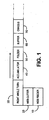
- Fig. 1 The input stages of a typical inserter system are depicted in Fig. 1 .
- a web feeder 10 At the input end of the inserter system, rolls or stacks of continuous printed documents, called a "web," are fed into the inserter system by a web feeder 10.
- the continuous web must be separated into individual document pages. This separation is typically carried out by a web cutter 20 that cuts the continuous web into individual document pages. Downstream of the web cutter 20, a right angle turn 30 may be used to reorient the documents, and/or to meet the inserter user's floor space requirements.
- the separated documents must subsequently be grouped into collations corresponding to the multi-page documents to be included in individual mail pieces. This gathering of related document pages occurs in the accumulator module 40 where individual pages are stacked on top of one another.
- the control system for the inserter senses markings on the individual pages to determine what pages are to be collated together in the accumulator module 40 .
- mail pieces may include varying numbers of pages to be accumulated. For example, the phone bill for a person who lives by himself may be much shorter than another phone bill representing calls made by a large family. It is this variation in the number of pages to be accumulated that makes the output of the accumulator 40 asynchronous, that is, not necessarily occurring at regular time intervals.
- a folder 50 Downstream of the accumulator 40, a folder 50 typically folds the accumulation of documents, so that they will fit in the desired envelopes. To allow the same inserter system to be used with different sized mailings, the folder 50 can typically be adjusted to make different sized folds on different sized paper. As a result, an inserter system must be capable of handling different lengths of accumulated and folded documents.
- a buffer transport 60 transports and stores accumulated and folded documents in series in preparation for transferring the documents to the synchronous inserter chassis 70 .
- the cutter is comprised of a guillotine blade that chops transverse sections of web into individual sheets.
- This guillotine arrangement requires that the web be stopped during the cutting process.
- the web cutter 20 transports the web in a sharp starting and stopping fashion and subjects the web to high accelerations and decelerations.
- the web feeder 10 may typically include a loop control module to provide a loop of slack web to be fed into the web cutter 20 .
- a loop control module to provide a loop of slack web to be fed into the web cutter 20 .
- the accelerations experienced by the web in the slack loop can be quite severe.
- the inertia experienced by the web from the sudden starting and stopping may cause it to tear or become damaged.
- An alternative to the guillotine cutter arrangement is an arrangement using a rotary cutter.
- a rotary cutter utilizes a blade positioned transversely along a roller in a roller arrangement through which the web is transported.
- the rotary cutter module can simultaneously serve to continuously transport the web while cutting it into to predetermined length pieces as the blade on the roller comes into contact with the paper while the roller turns.
- the rotary cutter arrangement does not include the disadvantage of sudden starting and stopping.
- a different disadvantage exists in that a rotary cutter requires a significant amount of time to decelerate when a downstream condition occurs that requires the system to stop. While the rotary cutter is decelerating to a stop, a number of additional sheets will be cut for which there may be no downstream space to accommodate.
- a frequent limitation on speed of an inserter system is the ability of the system to handle all of the generated documents if the system is required to stop.
- An input system may be capable of going very fast under non-stop operating conditions, but a problem arises during stopping if there isn't a means to handle all the sheets produced by the input system.
- a buffer module such as the ones described in U.S. patents 6,687,569 and 6,687,570 both issued on February 3, 2004 and assigned to the assignee of the present application, may be used to provide stopping stations, or "parking spots," for work-in-progress documents.
- an inserter input system should not be run faster than spaces for holding work in progress can be made available.
- the problem is less severe since sheets from the same mail piece are stored together in the buffer stations.
- the ratio of required stopping stations to the number of sheets generated will be greater, and the inserter input may be required to slow down.
- Refeed devices While solving one problem with rotary cutters, refeed devices cause another problem of their own. Refeed devices have been found to be insufficiently reliable for consistent feeding of cut sheets in the input subsystem of a high-speed inserter. For varying sheets sizes, paper weights, and curl conditions, a vertical stack feeding device has been found to incorrectly feed sheets from the bottom of the stack.
- US-B-6 176 483 discloses a high speed document separator and sequencing apparatus in which documents printed side-by-side on a wide roll, cut into individual documents, and turned through 90° by an inverter into an overlapping configuration are then separated using a speeded up pair of rollers.
- a preliminary sensor identifies advancement of a document towards the separator and sequencing apparatus, to begin rotation of a second document transport means of this apparatus, at the appropriate time, while a bar code reader reads the account identification printed on each document, for achieving proper account accumulation in a downstream accumulator.
- an inserter input system comprising: a web feeder for a web of printed material, the web feeder being arranged to feed the web at a first velocity in a first direction, a web slitting knife arranged for splitting the web along the first direction into at least two portions, a rotary web cutter arranged for cutting the portions of slit web transverse to the first direction while the web is transported through the rotary web cutter at the first velocity to form side-by-side individual sheets, a right angle turn mechanism downstream of the rotary web cutter, arranged for rearranging the individual sheets to be one on top of the other in a shingled arrangement, a high speed separation transport arrangement downstream of the right angle turn mechanism and arranged for pulling individual shingled sheets out from the shingled arrangement, whereby sheets are thereafter transported serially and separated by predetermined gaps, one or more sensors for scanning a code on an individual sheet processed by the inserter input system, the code indicating a number of sheets for a collation to which the scanned individual sheet belongs, the one or more sensors for scanning a code on
- a method for generating sheets from a continuous web for creating mail pieces comprising: feeding a web of printed material at a first velocity in a first direction, splitting the web along the first direction into at least two portions, cutting the portions of slit web transverse to the first direction while the web is transported at the first velocity to form side-by-side individual sheets, turning the side-by-side sheets at a right angle whereby the individual sheets are rearranged to be one on top of the other in a shingled arrangement, pulling individual shingled sheets out from the shingled arrangement whereby sheets are thereafter transported serially and separated by predetermined gaps, scanning a code on an individual sheet, the code indicating a number of sheets for a collation to which the scanned individual sheet belongs, sensing a position of the scanned individual sheet and providing a position indication of that sheet, and adjusting the first velocity as a function of the number of sheets in the collation prior to the step of pulling individual sheets out of the shingled arrangement, whereby a lower
- Embodiments of the present invention overcome disadvantage of the prior art by obtaining performance characteristics of a rotary cutter without having to use unreliable refeed devices to accommodate sheets generated during a stopping condition. Such embodiments also provide efficiency in that the preferred embodiment can handle the necessary number of sheets using relatively little floor space, and without significant lengthening of a buffer module.
- An inserter input system to be described begins with a web feeder providing a web of printed material.
- a web slitting knife splits the web along its direction of travel into at least two portions. While a preferred embodiment of the present invention operates on web in two side-by-side portions, in others a web may be split into any number of portions along its length.
- a rotary web cutter cuts the web in a direction transverse to the travel direction.
- the rotary cutter is typically comprised of a rotating roller with a blade along its length.
- a right angle turn mechanism receives each of the side-by-side sheets and reorients them by ninety degrees.
- the sheets are changed from the side-by-side orientation to a serial and shingled arrangement. This serial shingled arrangement provides storage capacity for sheets over a shorter length.
- a high speed separation nip pulls individual shingled sheets out from the shingled arrangement.
- the speed of the separation nip is such that a predetermined gap between the previously shingled sheets is formed. This gap is sufficient that downstream processing, such as selectively diverting sheets into accumulator bins, may be performed.
- the speed of the rotary cutter and right angle turn mechanism are controlled to adjust a quantity of sheets that would be generated from inertia during a deceleration of the system to a stop. Speeds are maintained such that, assuming the system may be required to stop at any time, no more sheets will be presented to the high speed separation nip than may be accommodated at available downstream parking spots.
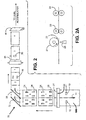
- FIG. 2 A preferred embodiment for implementing the present invention is depicted in Fig. 2 .
- the components depicted in Fig. 2 may be associated with the general input stages depicted in Fig. 1 , however it is not necessary that the particular components be part of any particular module, so long as they perform as described herein.
- a web 100 is drawn into the inserter input subsystem.
- Methods for transporting the web are known and may include rollers, or tractors pulling on holes along a perforated strip at the edges of the web.
- the web 100 is split into two side-by-side portions by a cutting device 11 .
- Cutting device 11 may be a stationary knife or a rotating cutting disc, or any other cutting device known in the art. While the embodiment in Fig. 2 shows the web being split into two portions, one skilled in the art will understand that a plurality of cutting devices 11 may be used to create more than two strands of web from the original one.
- processing steps described below will also be as applicable to webs that are split into more than two portions.
- Sensors 12 and 13 scan a mark or code printed on the web.
- the mark or code identify which mail piece that particular portion of web belongs to, and provides instructions for processing and assembling the mail pieces.
- the scanning process is useful for tracking the documents' progress through the mail piece assembly process. Once the location of a document is known based on a sensor reading, the document's position may be tracked throughout the system by monitoring the displacement of the transport system. In particular, encoders may be incorporated in the transport systems to give a reliable measurement of displacements that have occurred since a document was at a certain location.
- rotary cutter 21 is comprised of a cutting blade 22 that separates the web into the sheets as it rotates, and a stationary blade 25 . The cut is made across the web, transverse to the direction of transport.
- Fig. 2A provides a further side view of the rotary cutting operation.
- Nips 23 serve to further transport sheets downstream for further processing.
- nips 23 preferably help to create a predetermined gap between subsequent sets of cut sheets. This is accomplished by setting the transport speed of nips 23 to be slightly faster than the transport speed of the upstream web. Thus, when nips 23 grab the individual sheets designated as 1 and 2 , those sheets are pulled away from the slower moving portion of the uncut web that is still within the rotary cutter 21 .
- Nips 24 further serve to transport the sheets to the right angle turn 30 portion of the system.
- Right angle turn devices 30 are known in the art and will not be described in detail here. However, and exemplary right angle turn will comprise turn bars 32 and 33. Of the two paper paths formed by the right angle turn 30, turn bar 33 forms an inner paper path for transporting sheet 1 . Turn bar 32 forms a longer outer paper path on which sheet 2 travels.
- the turn bars 32 and 33 are further arranged so that a lead edge of a subsequent sheet on the shorter path will catch up to, and pass, the trailing edge of the prior document on the longer path.
- sheet 1 is the sheet that traveled on the shorter path through the right angle turn.
- Sheet 2 was previously side-by-side with sheet 1, but is now shingled on top of sheet 1 .
- Sheet 3 is a sheet that followed sheet 1 on the shorter paper path through the right angle turn 30 , and a lead portion of sheet 3 is now shingled under sheet 2 .
- sheet 4 previously the side-by-side portion paired with sheet 3 , is shingled on top of the rear portion of sheet 3 .
- the transport mechanisms between the rotary cutter 21 and high speed separation nip 34 operate at the same speeds.
- the transport mechanisms may be referred to herein as the "right angle turn transport,” and include rollers 23, 24, 36 , and turn bars 32 and 33 .
- the components of the right angle turn transport are electronically or mechanically geared to one another so that speeds are always consistent throughout.
- the shingling of sheets provides a means for storing a greater number of sheets in a smaller amount of space.
- the prior art problem of rotary cutters creating additional sheets during a stopping condition is partially mitigated.
- the rotary cutter 21 begins its deceleration.
- the right angle turn transports are subjected to a controlled deceleration to receive and store the extra sheets before coming to a complete stop.
- the speeds of the rotary cutter 21 and right angle turn transport are controlled so that no more sheets than may be accommodated are produced.
- the right angle turn transports pursuant to the present invention are capable of storing sheets during a stopping condition.
- a rotary feeder 21 is effectively used for input to a high speed inserter system without requiring a prior art re-feed device.
- the shingled sheets 1, 2, 3, 4 must be unshingled. This is accomplished by the high speed separation nip 34 .
- nip 34 operates at a higher speed than the upstream right angle transports and pulls the lead edges of sheets out of the shingled arrangement.
- the speed of the high speed separation nip 34 is selected so that downstream of the nip 34 the sheets are traveling serially, and are separated by a predetermined gap.
- high speed separation nip 34 operates at a constant high velocity, and is not controlled as part of a stoppage condition.
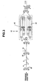
- a sensor 35 Downstream of nip 34 , a sensor 35 scans a code on the sheets. Once again this scanned code links the particular sheet to a set of instructions for assembling the mail pieces. Sensor 35 further is used to confirm that the sheets detected by sensors 12 and 13 have arrived as expected. Of particular interest at this stage of the production process is the number of sheets belonging to a particular mail piece, and which sheets go together to form the same mail piece. Based on mail piece information determined from the sensors, flipper gate 41 directs sheets belonging to the same mail piece to one of two accumulator bins 42 and 43 of accumulator 40 .
- accumulator 40 depicted in Fig. 3 is based on the one from U.S. Patent 6,644,657 issued November 11, 2003 .
- Another dual accumulator is described in U.S. Patent 5,083,769 issued January 28, 1992 .
- only one bin of the accumulator 40 is dedicated to providing a parking spot for additional sheets generated as a consequence of the deceleration period required for the rotary cutter 21 .
- the number of sheets cut by the rotary cutter 21 during deceleration will be a function of how fast the rotary cutter was going when the deceleration instruction is received.
- the number of sheets created during deceleration is not enough to know how may parking spots are required. Since all of the sheets for one collation are stored together, only one parking spot is needed for all the sheets of a given accumulation. Thus, if the collation to be stored includes four sheets, one parking space is sufficient and four sheets may be allowed to reach the high speed separation nip 34 . However, if the next four sheets each comprise single sheet collations, then a single parking space is insufficient, and three sheets may become improperly accumulated with sheets from different mail pieces.
- the number of sheets in a mail piece entering the accumulator 40 may be determined based on the code on the sheets scanned by sensors 12, 13 and 35 .
- the speeds of the rotary cutter 21 feed and the right angel turn transport mechanisms are adjusted to ensure that only one parking space will be needed to account for the additional sheets generated during rotary cutter 21 deceleration.
- the speed of the rotary cutter 21 and the right angle turn transports would be adjusted to a low velocity.
- the low velocity should be such that, if required to stop, the rotary cutter 21 would not produce any more sheets than would result in more than one sheet reaching the high speed separation roller 34 . If the mail piece prior to sheet 1 had included more than one sheet, then this would require a decrease in speed of the rotary cutter 21 and the right angle turn transports.
- the shingling arrangement downstream of the rotary cutter 21 allows that more than one sheet may be cut without necessarily causing more than one sheet to arrive at the nip 34 .
- the particular requirements for velocity changes will be functions of the characteristics of the hardware, and of the size of the paper that is being processed.
- the exemplary system characteristics are provided below to show how an embodiment would operate for particular conditions.
- the web 100 is being cut into 81 ⁇ 2 x 11 inch (21.6 x 27.9 cm) sheets, and that the rotary cutter 21 is capable of decelerating at 0.98 G's, with a maximum cutting rate of 36,000 cuts per hour.
- the velocity of the paper in the rotary cutter is a maximum of 110 in/s (2.8 m/s).
- the right angle turn transport is proportionally geared (electronically or mechanically) to the rotary cutter and operates at a maximum of 150 in/s (3.8 m/s).
- the distance from the rotary cutter blade 22 to a mid-point of both turning devices 32 and 33 is 16 inches (40.6 cm).
- the paper path length around the outer turning device 32 is 8.5 inches (21.6 cm) (the width of a sheet) longer than the paper path length around the inner turning device 33.
- the mid-point of the inner turning device 33 to the high speed separation nip is 17 inches (43.2 cm).
- the high speed separator nip 34 operates at a constant transport velocity 280 inches per second (7.1 m/sec).
- the rates of the rotary cutter 21 and right angle turn transports are adjusted at least every 500 microseconds second as a function of a sheet count per collation of "n" sheets positioned just prior to reaching the high speed separator nip 34 .
- sensors 12, 13, and 35 may be used to determine the position of the sheets.
- the position of sheets downstream of sensors 12 and 13 may be determined based on tracking an encoder count for the transports between the sensors and nip 34 .
- additional sensors may be used to determine the position of sheets just upstream of nip 34 .
- the rotary cutter 21 and the right angle turn transport will be required to operate at less than its full speed.
- the collations are comprised of four or more sheets, the shingled sheet arrangement and available parking spaces are readily able to absorb all of the additional sheets that would be generated while decelerating the rotary cutter 21 to a stop.
- the limitation on the speed of the inserter input system will be the speed at which the rotary cutter can operate.
- the right angle turn transport velocity and the rotary cutter 21 velocity are preferably adjusted in accordance with predetermined velocities, as a function of the sheet counts per collation, as depicted in the table above.
- the lead edges of the shingled sheets 1 and 2 from the same side-by-side pair will be 8.5 inches (21.6 cm) apart.
- the distance from a lead edge from Fig. 3 sheet 2 to sheet 3 will be 6.5 inches (16.5 cm) (this takes into account a four inch gap generated between pairs of side-by-side sheets resulting from the initial separation transport 23 ).
Landscapes
- Engineering & Computer Science (AREA)
- Mechanical Engineering (AREA)
- Life Sciences & Earth Sciences (AREA)
- Forests & Forestry (AREA)
- Separation, Sorting, Adjustment, Or Bending Of Sheets To Be Conveyed (AREA)
- Forming Counted Batches (AREA)
- Collation Of Sheets And Webs (AREA)
Claims (12)
- Système d'introduction d'inséreuse comprenant :un dispositif d'alimentation de bande (10) fournissant une bande de matériau imprimé, le dispositif d'alimentation de bande étant agencé pour distribuer la bande à une première vitesse dans une première direction ;un dispositif de fendage de bande (1) agencé pour fendre la bande le long de la première direction en au moins deux parties ;une coupeuse de bande rotative (21) agencée pour couper les parties de bande fendue transversalement à la première direction tandis que la bande est transportée via la coupeuse de bande rotative à la première vitesse pour former des feuilles individuelles côte à côte ;un mécanisme de virage à angle droit (30) en aval de la coupeuse de bande rotative (21), disposé de façon à réagencer les feuilles individuelles de façon qu'elles soient placées les unes sur les autres en un agencement en nappe ;un dispositif de transport de séparation à grande vitesse (34) en aval du mécanisme de virage à angle droit (30) et agencé pour tirer les feuilles en nappe individuelles hors de l'agencement en nappe, grâce à quoi les feuilles sont ensuite transportées en série et séparées par des espaces prédéterminés ;un ou plusieurs capteurs (12, 13) pour balayer un code sur une feuille individuelle traitée par le système d'introduction d'inséreuse, le code indiquant un nombre de feuilles pour un assemblage auquel appartient la feuille individuelle scannée, le ou les capteurs étant en outre agencés pour fournir une indication de position de la feuille individuelle dans le système d'introduction d'inséreuse ; etun dispositif de commande couplé au(x) capteur(s) (12, 13), le dispositif de commande étant agencé pour ajuster la première vitesse en fonction du nombre de feuilles dans l'assemblage arrivant au dispositif de transport de séparation à grande vitesse, grâce à quoi un moins grand nombre de feuilles dans l'assemblage correspond à une diminution de la première vitesse, et un plus grand nombre de feuilles dans l'assemblage correspond à une augmentation de la première vitesse.
- Système d'introduction d'inséreuse selon la revendication 1, dans lequel la coupeuse de bande rotative (21) est actionnable à une vitesse proportionnellement adaptée à la première vitesse.
- Système d'inséreuse selon la revendication 1 ou 2, comprenant, en outre, un premier dispositif de transport de séparation (23) en aval de la coupeuse rotative (21) et avant le mécanisme de virage à angle droit (30), le premier dispositif de transport de séparation étant agencé pour opérer à une deuxième vitesse supérieure à la première vitesse et amener un premier espace prédéterminé à se former entre des jeux consécutifs de feuilles individuelles côte à côte qui ont été coupées par la coupeuse rotative (21), le premier dispositif de transport de séparation étant proportionnellement adapté au dispositif d'alimentation de bande (10).
- Système d'inséreuse selon la revendication 3, dans lequel le mécanisme de virage à angle droit (30) est agencé pour opérer à la deuxième vitesse et le dispositif de transport de séparation à grande vitesse (34) est agencé pour opérer à une troisième vitesse constante, supérieure à la deuxième vitesse.
- Système d'introduction d'inséreuse selon la revendication 3 ou 4, dans lequel le dispositif de commande est agencé pour ajuster la première vitesse et la deuxième vitesse en fonction d'un nombre de feuilles dans l'assemblage arrivant au dispositif de transport de séparation à grande vitesse, grâce à quoi un moins grand nombre de feuilles dans l'assemblage correspond à une diminution de la première vitesse et de la deuxième vitesse, et un plus grand nombre de feuilles dans l'assemblage correspond à une augmentation de la première vitesse et de la deuxième vitesse.
- Système d'inséreuse selon l'une quelconque des revendications précédentes, dans lequel le mécanisme de virage à angle droit (30) comprend des barres de retournement à 45° (32, 33), parallèles, comprenant, en outre, une première barre de retournement (33) formant une trajectoire de papier intérieure ayant une première longueur de trajectoire de virage, et une deuxième barre de retournement (32) formant une trajectoire de papier extérieure ayant une deuxième longueur de trajectoire de virage, la deuxième longueur de trajectoire de virage étant supérieure à la première longueur de trajectoire de virage.
- Système d'inséreuse selon la revendication 6, dans lequel les première et deuxième barres de retournement (32, 33) sont espacées l'une de l'autre en fonction d'une longueur des feuilles de manière que l'agencement en nappe comprenne les feuilles transportées sur la trajectoire de papier intérieure positionnées sur le dessous de l'agencement en nappe et les feuilles transportées sur la trajectoire de papier extérieure positionnées sur le dessus de l'agencement en nappe.
- Système d'inséreuse selon l'une quelconque des revendications précédentes, comprenant, en outre, un mécanisme de transport pour transporter des feuilles de la coupeuse rotative (21) au mécanisme de virage à angle droit (30) et du mécanisme de virage à angle droit (30) au dispositif de transport de séparation à grande vitesse (34) ; et où le mécanisme de transport, et le mécanisme de virage à angle droit sont agencés pour décélérer jusqu'à un arrêt et retenir les feuilles au cas où survient une condition d'arrêt en aval.
- Procédé pour produire des feuilles à partir d'une bande continue (100) afin de créer des pièces de courrier, le procédé comprenant les étapes consistant à :distribuer une bande de matériau imprimé (100) à une première vitesse dans une première direction ;fendre la bande (100) le long de la première direction en au moins deux parties ;couper les parties de bande fendue transversalement à la première direction tandis que la bande est transportée à la première vitesse pour former des feuilles individuelles côte à côte (1, 2) ;faire tourner les feuilles côte à côte (1, 2) à angle droit, grâce à quoi les feuilles individuelles (1, 2) sont réagencées pour être placées les unes sur les autres en un agencement en nappe (1, 2, 3, 4) ;tirer les feuilles en nappe individuelles (1, 2) hors de l'agencement en nappe, grâce à quoi les feuilles (1, 2) sont ensuite transportées en série et séparées par des espaces prédéterminés ;balayer un code sur une feuille individuelle (1, 2), le code indiquant un nombre de feuilles (1, 2) pour un assemblage auquel appartient la feuille individuelle scannée (1, 2) ;détecter une position de la feuille individuelle scannée (1, 2), et fournir une indication de position de cette feuille (1, 2) ; etajuster la première vitesse en fonction du nombre de feuilles (1, 2) dans l'assemblage avant l'étape de traction des feuilles individuelles (1, 2) hors de l'agencement en nappe, grâce à quoi un moins grand nombre de feuilles (1, 2) dans l'assemblage correspond à une diminution de la première vitesse, et un plus grand nombre de feuilles (1, 2) dans l'assemblage correspond à une augmentation de la première vitesse.
- Procédé selon la revendication 9, comprenant, en outre, les étapes consistant à :postérieurement à la coupe de la bande dans la direction transversale, transporter les feuilles à une deuxième vitesse, supérieure à la première vitesse, et amener un premier espace prédéterminé à se former entre des jeux consécutifs de feuilles individuelles côte à côte, la deuxième vitesse étant en outre proportionnellement adaptée à la première vitesse.
- Procédé selon la revendication 10, dans lequel l'étape consistant à faire tourner les feuilles a lieu à la deuxième vitesse et l'étape consistant à tirer les feuilles a lieu à une troisième vitesse constante, supérieure à la deuxième vitesse.
- Procédé selon la revendication 10 ou 11, dans lequel, en outre :la première vitesse et la deuxième vitesse sont toutes deux ajustées en fonction du nombre de feuilles dans l'assemblage avant l'étape de traction des feuilles en nappe individuelles hors de l'agencement en nappe, grâce à quoi un moins grand nombre de feuilles dans l'assemblage correspond à une diminution de la première vitesse et de la deuxième vitesse, et un plus grand nombre de feuilles dans l'assemblage correspond à une augmentation de la première vitesse et de la deuxième vitesse.
Applications Claiming Priority (2)
| Application Number | Priority Date | Filing Date | Title |
|---|---|---|---|
| US445673 | 1995-05-22 | ||
| US10/445,673 US7021184B2 (en) | 2003-05-27 | 2003-05-27 | System and method for providing sheets to an inserter system using a rotary cutter |
Publications (3)
| Publication Number | Publication Date |
|---|---|
| EP1481817A2 EP1481817A2 (fr) | 2004-12-01 |
| EP1481817A3 EP1481817A3 (fr) | 2006-12-06 |
| EP1481817B1 true EP1481817B1 (fr) | 2010-08-11 |
Family
ID=33131543
Family Applications (1)
| Application Number | Title | Priority Date | Filing Date |
|---|---|---|---|
| EP20040012420 Expired - Lifetime EP1481817B1 (fr) | 2003-05-27 | 2004-05-26 | Système d'insertion utilisant un coupe-papier rotative |
Country Status (4)
| Country | Link |
|---|---|
| US (2) | US7021184B2 (fr) |
| EP (1) | EP1481817B1 (fr) |
| CA (1) | CA2468210C (fr) |
| DE (1) | DE602004028545D1 (fr) |
Families Citing this family (22)
| Publication number | Priority date | Publication date | Assignee | Title |
|---|---|---|---|---|
| US7021184B2 (en) * | 2003-05-27 | 2006-04-04 | Pitney Bowes Inc. | System and method for providing sheets to an inserter system using a rotary cutter |
| US20040237739A1 (en) * | 2003-05-27 | 2004-12-02 | Pitney Bowes Incorporated | System and method for providing sheets to an inserter system using a high speed cutter and right angle turn |
| US7111935B2 (en) * | 2004-01-21 | 2006-09-26 | Silverbrook Research Pty Ltd | Digital photofinishing system media cartridge |
| AU2004314460B2 (en) * | 2004-01-21 | 2008-08-28 | Memjet Technology Limited | Digital photofinishing system |
| US7735982B2 (en) * | 2004-01-21 | 2010-06-15 | Silverbrook Research Pty Ltd | Digital photofinishing system cartridge |
| US20060005675A1 (en) * | 2004-07-06 | 2006-01-12 | Scheffer, Inc. | Process of using a fixed size rotary cutter to cut products of variable repeat lengths |
| US7458578B2 (en) * | 2005-09-21 | 2008-12-02 | Pitney Bowes Inc. | Mailpiece fabrication system |
| US7637490B2 (en) * | 2005-10-03 | 2009-12-29 | Bowe Bell + Howell Company | Inserting systems and methods |
| US7607649B2 (en) * | 2005-10-03 | 2009-10-27 | Bowe Bell + Howell Company | Apparatuses and methods for staging and processing documents for sheet processing |
| US20080088083A1 (en) * | 2006-10-12 | 2008-04-17 | Bowe Bell + Howell Company | Apparatuses and methods for registering sheet articles |
| US7607653B2 (en) * | 2006-10-12 | 2009-10-27 | Bowe Bell + Howell Company | Systems and methods for maintaining the density of grouped sheet articles |
| US7662080B2 (en) * | 2006-10-12 | 2010-02-16 | Bowe Bell & Howell | Crease roller apparatuses and methods for using same |
| US7454882B2 (en) * | 2006-10-12 | 2008-11-25 | Bowe Bell + Howell Company | Methods for variably opening envelopes |
| US7611133B2 (en) * | 2006-10-13 | 2009-11-03 | Pitney Bowes Inc. | Method and system for enhanced cutter throughput |
| US7752948B2 (en) | 2006-12-01 | 2010-07-13 | Pitney Bowes Inc. | Method and apparatus for enhanced cutter throughput using an exit motion profile |
| EP2314533B1 (fr) * | 2009-10-23 | 2012-04-04 | Müller Martini Holding AG | Procédé de fabrication d'un produit d'impression |
| US8608163B1 (en) * | 2012-06-21 | 2013-12-17 | Xerox Corporation | Method and apparatus for constant velocity cut-sheet inversion in a printing system |
| US10102456B2 (en) * | 2016-04-29 | 2018-10-16 | Xerox Corporation | Systems and methods for implementing selectable input media routing of multiple input media forms from multiple axes in image forming devices |
| CN112571502B (zh) * | 2020-11-27 | 2025-11-18 | 浙江亚厦装饰股份有限公司 | 门板的包覆面自动跟踪切割机构 |
| EP4294628B1 (fr) * | 2021-02-19 | 2025-10-15 | Lohia Corp Limited | Système et procédé de transfert de pièces découpées de matériau en bande tournant les angles |
| CN113369165B (zh) * | 2021-05-14 | 2022-12-27 | 深圳市智弘自动化科技有限公司 | 一种工厂自动化分拣装置 |
| CN114889064B (zh) * | 2022-05-05 | 2023-08-08 | 江西快手机器人科技有限公司 | 手机保护套水口剪除及入胶口冲切机 |
Family Cites Families (30)
| Publication number | Priority date | Publication date | Assignee | Title |
|---|---|---|---|---|
| JPS5151084A (ja) * | 1974-10-29 | 1976-05-06 | Rengo Co Ltd | Shiitosetsudanseigyohoshiki |
| US4056023A (en) * | 1976-12-30 | 1977-11-01 | Westvaco Corporation | Single web sheet cutter and stacker |
| US4273319A (en) * | 1978-05-30 | 1981-06-16 | Bell & Howell Company | Document sequencer |
| US4753429A (en) * | 1986-11-13 | 1988-06-28 | Pitney Bowes Inc. | Collating station for inserting machine |
| US5228373A (en) * | 1990-01-08 | 1993-07-20 | Robert A. Foisie | Method and apparatus using electrostatic charges to temporarily hold packets of paper |
| US5048810A (en) * | 1990-11-19 | 1991-09-17 | Harris Graphics Corporation | Apparatus for adjusting an anglebar or a compensator roller in a folder of a printing press |
| US5207412A (en) * | 1991-11-22 | 1993-05-04 | Xerox Corporation | Multi-function document integrater with control indicia on sheets |
| US5359832A (en) * | 1992-09-04 | 1994-11-01 | Cloud Corporation | Accumulator and collator for packaging apparatus |
| US5538240A (en) * | 1994-11-04 | 1996-07-23 | Pitney Bowes | Right angle turn over module |
| US5664772A (en) * | 1994-11-04 | 1997-09-09 | Pitney Bowes Inc. | Apparatus and method for right angle turn over of sheet material |
| US5439208A (en) * | 1994-11-04 | 1995-08-08 | Bell & Howell Phillipsburg Company | Turnover-sequencer staging apparatus and method |
| US5887864A (en) * | 1995-09-27 | 1999-03-30 | Stevens; Kenneth A. | Method of and apparatus for processing and stacking printed forms |
| US5896797A (en) * | 1996-09-09 | 1999-04-27 | Thompson; Leroy J. | System and method for collating and stacking two streams of cut sheets |
| US5924686A (en) * | 1996-10-25 | 1999-07-20 | Pitney Bowes Inc. | Method for controlling the velocity of sheet separation |
| EP0869092B1 (fr) * | 1997-03-06 | 2002-07-03 | Grapha-Holding Ag | Méthode pour la fabrication de produits imprimés et un dispositif pour la mise en oeuvre de cette méthode |
| US6176483B1 (en) * | 1997-03-12 | 2001-01-23 | Bell & Howell Mail And Messaging Technologies Company | High speed document separator and sequencing apparatus |
| US6073527A (en) * | 1997-04-11 | 2000-06-13 | Marquip, Inc. | Method and apparatus for direct shingling of cut sheets at the cutoff knife |
| US6279636B1 (en) * | 1999-03-26 | 2001-08-28 | Daniel E. Miller | Method and apparatus for merging and attaching documents to envelopes |
| US6155560A (en) * | 1999-05-25 | 2000-12-05 | Heidelberger Druckmaschinen Ag | Method and apparatus for reorienting a printable medium |
| US20030197321A1 (en) * | 2002-04-19 | 2003-10-23 | Franz Schwab | Method and apparatus for forming groups of sheets from a plurality of sheets |
| US6378861B1 (en) * | 1999-11-19 | 2002-04-30 | Bell & Howell Mail And Messaging Technologies Company | Right angle stager apparatus and method |
| US6439563B1 (en) * | 2000-01-18 | 2002-08-27 | Currency Systems International, Inc. | Note feeder |
| US6443447B1 (en) * | 2000-12-29 | 2002-09-03 | Pitney Bowes Inc. | Method and device for moving cut sheets in a sheet accumulating system |
| US6519503B2 (en) * | 2001-05-07 | 2003-02-11 | Longford Equipment International Limited | Collation system and method |
| EP1277684B1 (fr) * | 2001-07-16 | 2006-05-31 | Grapha-Holding AG | Arrangement pour former un troisième courant à partir d'un premier et d'un deuxième courant de produits imprimés |
| GB2389574B (en) * | 2002-06-14 | 2005-07-06 | Pfe Internat Ltd | Collator |
| US6719522B1 (en) * | 2002-09-23 | 2004-04-13 | William H. Gunther | Sheet feeding |
| US20040173958A1 (en) * | 2003-03-04 | 2004-09-09 | Quad/Graphics, Inc. | Method of delivering a printed product to a binding or mailing line |
| US20040237739A1 (en) * | 2003-05-27 | 2004-12-02 | Pitney Bowes Incorporated | System and method for providing sheets to an inserter system using a high speed cutter and right angle turn |
| US7021184B2 (en) * | 2003-05-27 | 2006-04-04 | Pitney Bowes Inc. | System and method for providing sheets to an inserter system using a rotary cutter |
-
2003
- 2003-05-27 US US10/445,673 patent/US7021184B2/en not_active Expired - Lifetime
-
2004
- 2004-05-25 CA CA 2468210 patent/CA2468210C/fr not_active Expired - Fee Related
- 2004-05-26 EP EP20040012420 patent/EP1481817B1/fr not_active Expired - Lifetime
- 2004-05-26 DE DE200460028545 patent/DE602004028545D1/de not_active Expired - Lifetime
-
2005
- 2005-11-23 US US11/286,036 patent/US20060075860A1/en not_active Abandoned
Also Published As
| Publication number | Publication date |
|---|---|
| EP1481817A3 (fr) | 2006-12-06 |
| EP1481817A2 (fr) | 2004-12-01 |
| DE602004028545D1 (de) | 2010-09-23 |
| US20040237738A1 (en) | 2004-12-02 |
| CA2468210C (fr) | 2007-03-27 |
| US20060075860A1 (en) | 2006-04-13 |
| CA2468210A1 (fr) | 2004-11-27 |
| US7021184B2 (en) | 2006-04-04 |
Similar Documents
| Publication | Publication Date | Title |
|---|---|---|
| EP1481817B1 (fr) | Système d'insertion utilisant un coupe-papier rotative | |
| US6161828A (en) | Sheet collation device and method | |
| US4273319A (en) | Document sequencer | |
| EP0899129B1 (fr) | Système d'entrée de document à grande vitesse | |
| EP1016613B1 (fr) | Système pneumatique d'entrée de document à grande vitesse | |
| EP1911709B1 (fr) | Procédé et système pour le débit de découpe amélioré | |
| EP1683651B1 (fr) | Contrôle de mouvement pour l'entrée d'un système d'insertion à grande vitesse | |
| US6364305B1 (en) | System and method for providing sheets to an inserter system | |
| EP1577242B1 (fr) | Système et procédé pour fournir des feuilles à un système d'insertion utilisant un dispositif de coupe à haute vitesse et une rotation à angle droit | |
| EP1053963B1 (fr) | Sytème et procédé pour fournir des lots d'accumulation de documents à un système d'insertion | |
| EP1108563B1 (fr) | Méthode d'amenée d'enveloppes à un dispositif d'insertion | |
| US6687569B1 (en) | Configurable multi-station buffer transport for an inserter system | |
| EP1927563B1 (fr) | Procédé et appareil pour améliorer le rendement de découpe à l'aide d'un profil de mouvement de sortie | |
| US6607190B1 (en) | Apparatus for providing gap control for a high-speed check feeder | |
| EP1798176B1 (fr) | Dispositif et procédé pour la mise en sequence des produits coupés | |
| EP2714422B1 (fr) | Tampon inter-machine pour système de fabrication de pièce de courrier | |
| EP1334935B1 (fr) | Dispositif de manipulation de document avec mécanisme d'introduction dynamique et méthode correspondante | |
| CA2472870C (fr) | Appareil et methode pour accumuler les feuilles | |
| CA2558631A1 (fr) | Appareil et methode pour accumuler les feuilles |
Legal Events
| Date | Code | Title | Description |
|---|---|---|---|
| PUAI | Public reference made under article 153(3) epc to a published international application that has entered the european phase |
Free format text: ORIGINAL CODE: 0009012 |
|
| AK | Designated contracting states |
Kind code of ref document: A2 Designated state(s): AT BE BG CH CY CZ DE DK EE ES FI FR GB GR HU IE IT LI LU MC NL PL PT RO SE SI SK TR |
|
| AX | Request for extension of the european patent |
Extension state: AL HR LT LV MK |
|
| PUAL | Search report despatched |
Free format text: ORIGINAL CODE: 0009013 |
|
| AK | Designated contracting states |
Kind code of ref document: A3 Designated state(s): AT BE BG CH CY CZ DE DK EE ES FI FR GB GR HU IE IT LI LU MC NL PL PT RO SE SI SK TR |
|
| AX | Request for extension of the european patent |
Extension state: AL HR LT LV MK |
|
| RIC1 | Information provided on ipc code assigned before grant |
Ipc: B43M 3/04 20060101AFI20040908BHEP Ipc: B65H 29/56 20060101ALI20061102BHEP |
|
| 17P | Request for examination filed |
Effective date: 20070514 |
|
| AKX | Designation fees paid |
Designated state(s): DE FR GB |
|
| 17Q | First examination report despatched |
Effective date: 20071128 |
|
| GRAP | Despatch of communication of intention to grant a patent |
Free format text: ORIGINAL CODE: EPIDOSNIGR1 |
|
| GRAS | Grant fee paid |
Free format text: ORIGINAL CODE: EPIDOSNIGR3 |
|
| GRAA | (expected) grant |
Free format text: ORIGINAL CODE: 0009210 |
|
| AK | Designated contracting states |
Kind code of ref document: B1 Designated state(s): DE FR GB |
|
| REG | Reference to a national code |
Ref country code: GB Ref legal event code: FG4D |
|
| REF | Corresponds to: |
Ref document number: 602004028545 Country of ref document: DE Date of ref document: 20100923 Kind code of ref document: P |
|
| PLBE | No opposition filed within time limit |
Free format text: ORIGINAL CODE: 0009261 |
|
| STAA | Information on the status of an ep patent application or granted ep patent |
Free format text: STATUS: NO OPPOSITION FILED WITHIN TIME LIMIT |
|
| 26N | No opposition filed |
Effective date: 20110512 |
|
| PGFP | Annual fee paid to national office [announced via postgrant information from national office to epo] |
Ref country code: FR Payment date: 20110607 Year of fee payment: 8 |
|
| REG | Reference to a national code |
Ref country code: DE Ref legal event code: R097 Ref document number: 602004028545 Country of ref document: DE Effective date: 20110512 |
|
| REG | Reference to a national code |
Ref country code: FR Ref legal event code: ST Effective date: 20130131 |
|
| PG25 | Lapsed in a contracting state [announced via postgrant information from national office to epo] |
Ref country code: FR Free format text: LAPSE BECAUSE OF NON-PAYMENT OF DUE FEES Effective date: 20120531 |
|
| REG | Reference to a national code |
Ref country code: DE Ref legal event code: R082 Ref document number: 602004028545 Country of ref document: DE Representative=s name: HOFFMANN - EITLE PATENT- UND RECHTSANWAELTE PA, DE Ref country code: DE Ref legal event code: R081 Ref document number: 602004028545 Country of ref document: DE Owner name: DMT SOLUTIONS GLOBAL CORP. (N.D.GES.D. STAATES, US Free format text: FORMER OWNER: PITNEY BOWES, INC., STAMFORD, CONN., US |
|
| REG | Reference to a national code |
Ref country code: GB Ref legal event code: 732E Free format text: REGISTERED BETWEEN 20191128 AND 20191204 |
|
| PGFP | Annual fee paid to national office [announced via postgrant information from national office to epo] |
Ref country code: DE Payment date: 20230530 Year of fee payment: 20 |
|
| PGFP | Annual fee paid to national office [announced via postgrant information from national office to epo] |
Ref country code: GB Payment date: 20230529 Year of fee payment: 20 |
|
| REG | Reference to a national code |
Ref country code: DE Ref legal event code: R071 Ref document number: 602004028545 Country of ref document: DE |
|
| REG | Reference to a national code |
Ref country code: GB Ref legal event code: PE20 Expiry date: 20240525 |
|
| PG25 | Lapsed in a contracting state [announced via postgrant information from national office to epo] |
Ref country code: GB Free format text: LAPSE BECAUSE OF EXPIRATION OF PROTECTION Effective date: 20240525 |
|
| PG25 | Lapsed in a contracting state [announced via postgrant information from national office to epo] |
Ref country code: GB Free format text: LAPSE BECAUSE OF EXPIRATION OF PROTECTION Effective date: 20240525 |