EP1481937A1 - Modulares und anpassungsfähiges Bremsensystem für eine Aufzugsscheibe - Google Patents
Modulares und anpassungsfähiges Bremsensystem für eine Aufzugsscheibe Download PDFInfo
- Publication number
- EP1481937A1 EP1481937A1 EP20040252748 EP04252748A EP1481937A1 EP 1481937 A1 EP1481937 A1 EP 1481937A1 EP 20040252748 EP20040252748 EP 20040252748 EP 04252748 A EP04252748 A EP 04252748A EP 1481937 A1 EP1481937 A1 EP 1481937A1
- Authority
- EP
- European Patent Office
- Prior art keywords
- plate
- brake
- calipers
- sheave
- plates
- Prior art date
- Legal status (The legal status is an assumption and is not a legal conclusion. Google has not performed a legal analysis and makes no representation as to the accuracy of the status listed.)
- Granted
Links
- 239000012530 fluid Substances 0.000 claims description 12
- 230000002401 inhibitory effect Effects 0.000 claims description 6
- 230000008878 coupling Effects 0.000 claims description 5
- 238000010168 coupling process Methods 0.000 claims description 5
- 238000005859 coupling reaction Methods 0.000 claims description 5
- 230000004048 modification Effects 0.000 abstract description 8
- 238000012986 modification Methods 0.000 abstract description 8
- 238000010276 construction Methods 0.000 description 4
- 239000000463 material Substances 0.000 description 4
- 230000008901 benefit Effects 0.000 description 2
- 230000006872 improvement Effects 0.000 description 2
- 238000007689 inspection Methods 0.000 description 2
- 229910001092 metal group alloy Inorganic materials 0.000 description 2
- 230000008439 repair process Effects 0.000 description 2
- RYGMFSIKBFXOCR-UHFFFAOYSA-N Copper Chemical compound [Cu] RYGMFSIKBFXOCR-UHFFFAOYSA-N 0.000 description 1
- 230000009471 action Effects 0.000 description 1
- 239000000853 adhesive Substances 0.000 description 1
- 230000001070 adhesive effect Effects 0.000 description 1
- 230000001174 ascending effect Effects 0.000 description 1
- 230000000295 complement effect Effects 0.000 description 1
- 229910052802 copper Inorganic materials 0.000 description 1
- 239000010949 copper Substances 0.000 description 1
- 230000007812 deficiency Effects 0.000 description 1
- 239000002783 friction material Substances 0.000 description 1
- 238000009434 installation Methods 0.000 description 1
- 238000003754 machining Methods 0.000 description 1
Images


Classifications
-
- B—PERFORMING OPERATIONS; TRANSPORTING
- B66—HOISTING; LIFTING; HAULING
- B66D—CAPSTANS; WINCHES; TACKLES, e.g. PULLEY BLOCKS; HOISTS
- B66D5/00—Braking or detent devices characterised by application to lifting or hoisting gear, e.g. for controlling the lowering of loads
- B66D5/02—Crane, lift hoist, or winch brakes operating on drums, barrels, or ropes
- B66D5/24—Operating devices
- B66D5/30—Operating devices electrical
-
- B—PERFORMING OPERATIONS; TRANSPORTING
- B66—HOISTING; LIFTING; HAULING
- B66B—ELEVATORS; ESCALATORS OR MOVING WALKWAYS
- B66B5/00—Applications of checking, fault-correcting, or safety devices in elevators
- B66B5/02—Applications of checking, fault-correcting, or safety devices in elevators responsive to abnormal operating conditions
- B66B5/16—Braking or catch devices operating between cars, cages, or skips and fixed guide elements or surfaces in hoistway or well
- B66B5/18—Braking or catch devices operating between cars, cages, or skips and fixed guide elements or surfaces in hoistway or well and applying frictional retarding forces
-
- B—PERFORMING OPERATIONS; TRANSPORTING
- B66—HOISTING; LIFTING; HAULING
- B66D—CAPSTANS; WINCHES; TACKLES, e.g. PULLEY BLOCKS; HOISTS
- B66D5/00—Braking or detent devices characterised by application to lifting or hoisting gear, e.g. for controlling the lowering of loads
- B66D5/02—Crane, lift hoist, or winch brakes operating on drums, barrels, or ropes
- B66D5/12—Crane, lift hoist, or winch brakes operating on drums, barrels, or ropes with axial effect
Definitions
- This invention relates to brakes used in elevators and, in particular, to a brake that applies a braking force directly to an elevator sheave and that is configured for use in existing elevators without requiring modification of the elevators.
- a conventional elevator includes an elevator car and a counterweight disposed within an elevator shaft at opposite ends of a plurality of cables. Portions of each cable intermediate the elevator car and the counterweight are disposed within grooves formed in the circumference of a sheave that is located above the elevator car and counterweight and is rotatably driven by a motor to control the ascent and descent of the elevator car.
- One or more gears may be disposed between the motor and sheave or the sheave may be directly rotated by the motor.
- the sheave, motor, and any motor controls may be located within a control room above the elevator shaft or within the elevator shaft itself.
- the elevator car and counterweight move upward and downward within the elevator shaft on rails.
- Conventional elevators also include one or more emergency braking systems to prevent the elevator car from ascending or descending too quickly in the event of a system failure such as a broken cable.
- the brakes may be applied in a variety of locations. For example, some brakes are mounted between the elevator car and the rails on which the elevator car rides. These brakes produce rough braking and may inflict damage to the elevator car rails. Further, these brakes are difficult to install in existing elevators.
- Another type of brake apply a braking force directly to the cables in the elevator. This type of brake may inflict damage to the cables (requiring extensive inspection and downtime for the elevator) and is difficult to install in existing elevators.
- Another type of conventional brake includes a disc mounted coaxially with the elevator sheave and an actuator that applies a braking force to one side of the disc while another type of conventional brake includes calipers that apply a braking force to either side of a disc or to a shaft.
- These type of brake requires modifications in existing elevators and the caliper brakes are also generally limited to use with discs of certain widths.
- Yet another type of conventional brake applies a braking force to the outer or inner diameter of the sheave.
- This type of brake also requires extensive modifications in existing elevators (e.g., machining flats or bosses on the sheave surface) and the friction material in the brake must often be specially adapted for use with the sheave.
- 4,923,055 discloses a brake including two calipers that apply a braking force to either longitudinal end of the sheave.
- This brake is also unsuitable for use with existing elevators, however, as the brake actuator relies on bosses machined into an inner diameter at one end of the sheave.
- the present invention provides a brake for selectively inhibiting rotation of a sheave supporting at least one cable connected to an elevator car and a counterweight.
- a brake in accordance with one embodiment of the present invention includes first and second calipers arranged for selective engagement with first and second longitudinal ends of the sheave, respectively.
- Each of the first and second calipers includes a first plate, a second plate that is movable relative to the first plate, and a spring biasing the second plate in a first direction away from the first plate and towards a corresponding end of the first and second longitudinal ends of the sheave.
- Each of the first and second calipers further includes means for selectively urging the second plate in a second direction opposite the first direction.
- the urging means may apply, for example, an electromagnetic force, a hydraulic force, or a pneumatic force to urge the second plate in the second direction.
- a brake in accordance with the present invention represents and improvement as compared to conventional elevator brakes.
- the inventive brake is configured for use with existing elevators without requiring modification of the elevator.
- the inventive brake applies a braking force directly to the elevator sheave without any modification to the sheave and is adaptable to wide variations in the width and diameter of the sheave as well as variations in load.
- Figure 1 is a perspective view of a conventional elevator incorporating a brake in accordance with one embodiment of the present invention.
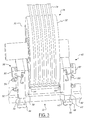
- Figures 2-3 are perspective views of a brake in accordance with one embodiment of the invention as applied against an elevator sheave.
- Figure 4 is a cross-sectional view of a brake in accordance with one embodiment of the present invention.
- Figure 5 is a cross-sectional view of a brake in accordance with another embodiment of the present invention.
- Figure 1 illustrates an elevator 10 incorporating a brake 12 in accordance with one embodiment of the present invention.
- Figure 1 illustrates a conventional passenger or freight elevator, it should be understood that the inventive brake 12 may find application in other similar devices such as dumbwaiters, hoists, cranes and escalators and other lifting equipment.
- brake 12 offers the significant advantage of use on existing elevators, it should be understood that brake 12 could also be used in new elevators.
- Elevator 10 is conventional in the art. Elevator 10 includes an elevator car 14 and a counterweight 16 disposed within an elevator shaft 18. Car 14 and counterweight 16 ascend and descend within shaft 18 on rails 20, 22, respectively. A stop 24 disposed at the bottom of shaft 18 cushions car 14 at is lowest point of descent. Car 14 and counterweight 16 are disposed at opposite ends of a plurality of cables 26. Cables 26 extend over a sheave 28 located above car 14 and counterweight 16 in a control room 28 or proximate the top of the elevator shaft. Cables 26 rest within grooves (not shown) formed in sheave 28 intermediate the longitudinal ends 30, 32 of sheave 28. Sheave 28 may be rotatably driven by a motor 34 subject to conventional motor controls 36. Alternatively, sheave 28 may be driven by other actuators (e.g., hydraulic actuation).
- a motor 34 subject to conventional motor controls 36. Alternatively, sheave 28 may be driven by other actuators (e.g., hydraulic actuation).
- Brake 12 may include first and second calipers 38, 40, a rail 42, means, such as frame 44, for locating and supporting rail 42, means, such as plates 46, 48 and fasteners 50, for mounting calipers 38, 40 to rail 42 and means, such as pins 52, 54, for adjusting the spacing of calipers 38,40.
- Calipers 38, 40 are provided to apply a braking force to ends 30, 32 of sheave 28.
- calipers 38, 40 are substantially the same in construction. It should be understood, however, that the construction of each caliper 38, 40 may vary. It should also be understood that additional calipers could be employed to assist calipers 38, 40.
- Calipers 38, 40 may include plates 56, 58 and 60, 62, friction pads 64, 66, pins 68, 70, springs 72, 74, and means for selectively urging plates 58, 62 in one direction towards plates 56, 60.
- the urging means may comprise means for generating an electromagnetic force to urge plates 58, 62 towards plates 56, 60.
- the generating means may include coils 76, 78 and means, such as controllers 80, 82 (best shown in Fig. 3), for selectively energizing coils 76, 78.
- Plates 56, 60 provide structural support for the other components of calipers 38, 40.
- Plates 56, 60 may be made from a material having a relatively low magnetic reluctance such as a metal alloy. Plates 56, 60 are substantially square in the illustrated embodiment, but it should be understood that the shape of plates 56, 60 may be varied without departing from the spirit of the present invention.
- Plates 56, 60 may include through bores 84, 86 configured to receive pins 68, 70 coupling plates 56, 60 to plates 58 62, through bores (not shown) configured to receive pins 52, 54 extending between calipers 38, 40, and recesses 88, 90 and 92, 94 configured to receive springs 72, 74 and coils 76, 78.
- Plates 58, 62 are provided to apply a braking force against ends 30, 32 of sheave 28. Plates 58, 62 may also be made from a material having a relatively low magnetic reluctance such as a metal alloy. In the illustrated embodiment, plates 58, 62 are substantially square in shape and slightly smaller in dimension than plates 56, 60. It should again be understood, however, that the size and shape of plates 58, 62 may be varied without departing from the spirit of the present invention. Plates 58, 62 may include bores 96, 98 configured to receive pins 68, 70 coupling plates 56, 60 to plates 58, 62 and through bores (not shown) configured to receive pins 52, 54 extending between calipers 38, 40.
- brake 12 is less likely to damage elevator 10 than conventional brakes. Further, brake 12 may be repeatedly set and released without requiring inspection, repair or downtime to the elevator.
- Friction pads 64, 66 are provided to increase the friction between calipers 38, 40 and sheave 28 and are conventional in the art. Friction pads 64, 66 may be affixed to plates 58, 62 using an adhesive or another conventional fastener.
- Pins 68, 70 are provided to couple plates 56, 60 and plates 58, 62 to one another, respectively, but allow for movement of plates 58, 62 relative to plates 56, 60.
- Each pin 68, 70 includes a shank 100 extending through bores 84, 86 and 96, 98 of plates 56, 60 and plates 58, 62 and a head 102 disposed on one side of plates 56, 60 opposite plates 58, 62.
- Springs 72, 74 are provided to bias plates 58, 62 in one direction away from plates 56, 60 and towards a corresponding end 30, 32 of sheave 28 to set brake 12.
- Springs 72, 74 may be made from conventional materials.
- Springs 72, 74 are disposed within recesses 88, 90 in plates 56, 60. Because each caliper 38, 40 includes springs 72, 74, brake 12 has redundant braking capabilities and improves elevator safety. Further, each of calipers 38, 40 may include a plurality of springs 72, 74 to ensure each caliper 38, 40 of brake 12 is set in the event of a failure of any one spring 72, 74 for that caliper 38, 40.
- Springs 72, 74 may be evenly spaced in a circle or in concentric circles. However, it will be understood that other arrangements are possible.
- Coils 76, 78 are provided to create an electromagnetic force attracting plates 58, 62 towards plates 56, 60 and away from ends 30, 32 of sheave 28 to release brake 12. Coils 76, 78 may also be made from conventional materials such as copper. Coils 76, 78 are disposed within recesses 92, 94 in plates 56, 60. In the illustrated embodiment, coils 76, 78 are disposed radially outwardly of springs 72, 74. The relative radial position of springs 72, 74 and coils 76, 78 may be reversed, however, without departing from the spirit of the present invention.
- Controllers 80, 82 are provided to selectively energize coils 76, 78.
- Controllers 80, 82 may comprise programmable microcontrollers or discrete circuits that selectively energize coils 76, 78 responsive to a predetermined condition (e.g., a rapid ascent of car 14) as detected by, for example, conventional speed sensors.
- controllers 80, 82 may be powered and transmit and receive control signals through cables 104, 106 or buses from a central controller 108 mounted at one end of rail 42.
- the programming of controllers 80, 82, 108 is considered to be part of the ordinary skill in the art.
- Rail 42 is provided to allow adjustment of the longitudinal location of calipers 38, 40 relative to sheave 28 and provides structural support for handling braking torque.
- Rail 42 extends parallel to the axis of rotation of sheave 28.
- Rail 42 may be tubular and substantially rectangular in cross-section. It should be understood, however, that the size, shape and configuration of rail 42 may be varied without departing from the spirit of the present invention.
- Frame 44 is provided to locate and support rail 42 relative to sheave 28.
- Rail 42 may be mounted to frame 44 using bolts, screws, or other conventional fasteners. It should be understood that frame 44 may be constructed in a variety of ways. It should also be understood that frame 44 is not required to locate and support rail 42 and that rail 42 may be located and supported relative to sheave 28 in a variety of ways.
- Plates 46, 48 and fasteners 50 are provided to mount calipers 38, 40 to rail 42. Plates 48, 50 are disposed on one side of rail 42 while calipers 38, 40 are disposed on an opposite side of rail 42. Fasteners 50 extend through plates 46, 48 and into calipers 38, 40 and couple plates 46, 48 to calipers 38, 40 on opposite sides of rail 42. In the illustrated embodiment, each caliper 38, 40 is coupled to a corresponding plate 46, 48 using four fasteners 50 (two on each side of rail 42). It should be understood, however, that the number of fasteners 50 may be varied without departing from the spirit of the present invention. Fasteners 50 may comprise screws, bolts, pins, or other conventional fasteners. The mounting arrangement of calipers 38, 40 on rail 42 enables calipers 38, 40 to be easily moved along rail 42 to enable adjustment of calipers 38, 40 relative to sheave 28.
- Pins 52, 54 provide a means for adjusting the spacing of calipers 38, 40.
- Pins 52, 54 extend between calipers 38, 40 and couple calipers 38, 40, extending through plates 56, 60 and 58, 62 in calipers 38, 40. At least one of calipers 38, 40 is movable along pins 52, 54 to adjust the spacing between calipers 38, 40.
- Nuts 110 may be disposed on either end of pins 52, 54 to secure the location of calipers 38, 40 on pins 52, 54. In the illustrated embodiment, two pins 52, 54 extend between calipers 38, 40. It should be understood, however, that the number of pins 52, 54 may be varied without departing from the spirit of the present invention.
- the use of pins 52, 54 enables brake 12 to be used with a wide variety of sheaves 28 and further facilitates use of brake 12 with existing elevators.
- Brake 12' in accordance with another embodiment of the present invention for inhibiting rotation of a sheave 28 supporting at least one cable 26 connected to an elevator car 14 and a counterweight 16 will be described.
- Brake 12' is substantially similar to brake 12 and, therefore, similar components will not be described in detail.
- Brake 12' may include first and second calipers 38', 40'.
- Brake 12' may again include a rail 42, means, such as frame 44, for locating and supporting rail 42, means, such as plates 46, 48 and fasteners 50, for mounting calipers 38', 40' to rail 42 and means, such as pins 52, 54, for adjusting the spacing of calipers 38', 40'.
- Calipers 38', 40' are provided to apply a braking force to ends 30, 32 of sheave 28.
- calipers 38', 40' are again substantially the same in construction. It should be understood, however, that the construction of each caliper 38', 40' may vary.
- Calipers 38', 40' may include plates 56' 58' and 60', 62', friction pads 64, 66, pins 68, 70, springs 72, 74, and means for selectively urging plates 58', 62' in one direction towards plates 56', 60'.
- the urging means may include pistons 112, 114 coupled to plates 58', 62' and means for applying fluid pressure against pistons 112, 114 to urge pistons 112, 114 and plates 58', 62' in one direction towards plates 56', 60' and away from ends 30, 32 of sheave 28.
- Plates 56', 60' provide structural support for the other components of calipers 38', 40' and are substantially similar to plates 56, 60 of brake 12. Plates 56', 60' define cylinders having stepped apertures 116, 118 in which pistons 112, 114 are disposed. Plates 58', 62' are disposed on one side of plates 56', 60' and include bores 96, 98 configured to receive pins 68, 70 extending through pistons 112, 114. Springs 72, 74 are provided to bias plates 58', 62' in one direction away from plates 56', 60' and towards a corresponding end 30, 32 of sheave 28 to set brake 12.
- Each of calipers 38', 40' may again include a plurality of springs 72, 74 to ensure brake 12 is set in the event of a failure of any one of springs 72,74.
- Springs 72, 74 may be disposed radially outwardly of pistons 112, 114.
- Pistons 112, 114 are coupled to plates 58', 62' using pins 68, 70 or other fasteners. Pistons 112, 114 are disposed with apertures 116, 118 in plates 56', 60' and are shaped complementary to apertures 116, 118 with each of pistons 112, 114 and plates 56', 60' defining radially inner and outer shoulders. Pistons 112, 114 and plates 56', 60' define fluid cavities 120, 122 between these shoulders. Seals 124 are disposed in grooves in pistons 112, 114 on either side of fluid cavities 120, 122 to prevent the loss of fluid pressure.
- Brake 12' further includes means for applying fluid pressure to pistons 112, 114 to thereby urge pistons 112, 114 in one direction. This action urges plates 58', 62' towards plates 56', 60' and away from sheave 28 to release brake 12'.
- the fluid pressure may be hydraulic or pneumatic and may be supplied in a conventional manner responsive to mechanical or electrical controls detecting a predetermined operating condition of elevator 10.
- a brake in accordance with the present invention represents a significant improvement as to conventional elevator brakes.
- the inventive brake is configured for use with existing elevators without requiring modification to the components of the elevator.
- the inventive brake is also capable of accommodating a wide variety of sheave widths and diameters and varying loads found in existing elevators.
- the inventive brake is less likely to damage components of the elevator upon application of the brake, thereby limiting elevator downtime and repair costs, because the brake is applied to the sheave rather than weaker components such as the rails or cables.
- the inventive brake provides braking redundancy in the event of a failure because each caliper is separately controlled.
- the inventive brake can be repeatedly set and released without requiring extensive manual resetting between actuations.
- the inventive brake enables application of braking force to the elevator that provides a smoother deceleration of the elevator as compared to some conventional brakes that apply a braking force to the rails or cables.
Landscapes
- Engineering & Computer Science (AREA)
- Mechanical Engineering (AREA)
- Cage And Drive Apparatuses For Elevators (AREA)
- Braking Arrangements (AREA)
Applications Claiming Priority (2)
| Application Number | Priority Date | Filing Date | Title |
|---|---|---|---|
| US10/448,653 US7104367B2 (en) | 2003-05-30 | 2003-05-30 | Modular and adaptable brake system for an elevator sheave |
| US448653 | 2003-05-30 |
Publications (2)
| Publication Number | Publication Date |
|---|---|
| EP1481937A1 true EP1481937A1 (de) | 2004-12-01 |
| EP1481937B1 EP1481937B1 (de) | 2009-07-15 |
Family
ID=33131615
Family Applications (1)
| Application Number | Title | Priority Date | Filing Date |
|---|---|---|---|
| EP04252748A Expired - Lifetime EP1481937B1 (de) | 2003-05-30 | 2004-05-12 | Modulares und anpassungsfähiges Bremsensystem für eine Aufzugsscheibe |
Country Status (3)
| Country | Link |
|---|---|
| US (1) | US7104367B2 (de) |
| EP (1) | EP1481937B1 (de) |
| DE (1) | DE602004021989D1 (de) |
Cited By (2)
| Publication number | Priority date | Publication date | Assignee | Title |
|---|---|---|---|---|
| DE102004063130A1 (de) * | 2004-12-22 | 2006-07-13 | Logos-Innovationen Gmbh | Hebevorrichtung mit einer Antriebseinheit zum Heben einer Lastaufnahme |
| CN106163959A (zh) * | 2014-04-03 | 2016-11-23 | 蒂森克虏伯电梯股份公司 | 具有制动装置的电梯 |
Families Citing this family (10)
| Publication number | Priority date | Publication date | Assignee | Title |
|---|---|---|---|---|
| US7428951B2 (en) * | 2004-08-19 | 2008-09-30 | Mitsubishi Denki Kabushiki Kaisha | Brake device for elevator |
| WO2009018434A1 (en) * | 2007-07-31 | 2009-02-05 | Thyssenkrupp Elevator Capital Corporation | Method and apparatus to minimize re-leveling in high rise high speed elevators |
| FI125327B (fi) * | 2009-01-12 | 2015-08-31 | Kone Corp | Hissikorin liikkeen estävällä lukituslaitteella varustettu hissi ja hissikorin liikkeen estävä lukituslaite |
| US8485318B2 (en) * | 2009-05-15 | 2013-07-16 | Paul J. Doran | Elevator rope braking system |
| DE102012011539A1 (de) * | 2012-06-08 | 2013-12-12 | Siemag Tecberg Gmbh | Scheibenbremsanlage |
| WO2014021896A1 (en) * | 2012-08-02 | 2014-02-06 | Otis Elevator Company | Hydraulic brake system for elevator |
| CN104444689B (zh) * | 2014-11-18 | 2016-08-17 | 苏州通润驱动设备股份有限公司 | 一种曳引轮安全保护装置及其紧急制停电梯轿厢的方法 |
| ES2619510B1 (es) * | 2015-12-23 | 2018-01-04 | Alzola Elizondo, Luis | Maquinaria de ascensor integrada |
| US10618775B2 (en) | 2016-11-18 | 2020-04-14 | Otis Elevator Company | Retrofitting an elevator machine with primary and secondary braking |
| US10737908B2 (en) | 2016-11-22 | 2020-08-11 | Otis Elevator Company | Method and kit for retrofitting elevator machines with thrust bearing, and retrofitted elevator machine |
Citations (3)
| Publication number | Priority date | Publication date | Assignee | Title |
|---|---|---|---|---|
| US4108280A (en) * | 1976-02-13 | 1978-08-22 | Canadian General Electric Company, Ltd. | Plural rope friction hoist with braking apparatus |
| JPH11335041A (ja) * | 1998-05-29 | 1999-12-07 | Mitsubishi Electric Corp | エレベータ用巻上機 |
| JP2002020064A (ja) * | 2000-07-07 | 2002-01-23 | Mitsubishi Electric Corp | エレベータ用巻上機 |
Family Cites Families (14)
| Publication number | Priority date | Publication date | Assignee | Title |
|---|---|---|---|---|
| AU580453B2 (en) | 1985-11-04 | 1989-01-12 | Johns Perry Industries Pty. Ltd. | Lift sheave |
| US4923055A (en) | 1989-01-24 | 1990-05-08 | Delaware Capital Formation, Inc. | Safety mechanism for preventing unintended motion in traction elevators |
| JPH0768989B2 (ja) * | 1989-10-13 | 1995-07-26 | 三菱電機株式会社 | エレベータの捲上げ装置用ブレーキ装置 |
| US4977982A (en) | 1989-12-26 | 1990-12-18 | Otis Elevator Company | Elevator sheave brake safety |
| US5007505A (en) | 1990-03-19 | 1991-04-16 | Northern Elevator Limited | Elevator traction sheave brake |
| US5101939A (en) | 1990-04-13 | 1992-04-07 | Otis Elevator Company | Disk brake for elevator |
| US5435209A (en) | 1992-06-26 | 1995-07-25 | Wittur Aufzugteile Gmbh & Co. | Drive unit for a hoisting apparatus, in particular for a passenger or freight elevator |
| US5669469A (en) | 1995-04-03 | 1997-09-23 | Otis Elevator Company | Integrated elevator drive machine and brake assembly |
| JP3614221B2 (ja) | 1995-10-31 | 2005-01-26 | 三菱電機株式会社 | エレベータ巻上機用ブレーキ装置 |
| DE69730767T2 (de) | 1996-03-22 | 2005-09-29 | Sanyo Kogyo Co. Ltd., Suita | Bremse für Hebegerät |
| US6371248B1 (en) | 1998-12-14 | 2002-04-16 | Inventio Ag | Drive unit for elevators |
| US6293376B1 (en) * | 1999-11-22 | 2001-09-25 | Magnetar Technologies Ltd | Apparatus including eddy current braking system |
| JP2001355659A (ja) | 2000-04-27 | 2001-12-26 | Inventio Ag | エレベーター駆動装置用ディスクブレーキ |
| US6439355B1 (en) * | 2000-12-18 | 2002-08-27 | The Hilliard Corporation | Electromagnetic spring-actuated brake system |
-
2003
- 2003-05-30 US US10/448,653 patent/US7104367B2/en not_active Expired - Fee Related
-
2004
- 2004-05-12 EP EP04252748A patent/EP1481937B1/de not_active Expired - Lifetime
- 2004-05-12 DE DE602004021989T patent/DE602004021989D1/de not_active Expired - Lifetime
Patent Citations (3)
| Publication number | Priority date | Publication date | Assignee | Title |
|---|---|---|---|---|
| US4108280A (en) * | 1976-02-13 | 1978-08-22 | Canadian General Electric Company, Ltd. | Plural rope friction hoist with braking apparatus |
| JPH11335041A (ja) * | 1998-05-29 | 1999-12-07 | Mitsubishi Electric Corp | エレベータ用巻上機 |
| JP2002020064A (ja) * | 2000-07-07 | 2002-01-23 | Mitsubishi Electric Corp | エレベータ用巻上機 |
Non-Patent Citations (2)
| Title |
|---|
| PATENT ABSTRACTS OF JAPAN vol. 2000, no. 03 30 March 2000 (2000-03-30) * |
| PATENT ABSTRACTS OF JAPAN vol. 2002, no. 05 3 May 2002 (2002-05-03) * |
Cited By (2)
| Publication number | Priority date | Publication date | Assignee | Title |
|---|---|---|---|---|
| DE102004063130A1 (de) * | 2004-12-22 | 2006-07-13 | Logos-Innovationen Gmbh | Hebevorrichtung mit einer Antriebseinheit zum Heben einer Lastaufnahme |
| CN106163959A (zh) * | 2014-04-03 | 2016-11-23 | 蒂森克虏伯电梯股份公司 | 具有制动装置的电梯 |
Also Published As
| Publication number | Publication date |
|---|---|
| US7104367B2 (en) | 2006-09-12 |
| EP1481937B1 (de) | 2009-07-15 |
| DE602004021989D1 (de) | 2009-08-27 |
| US20040251088A1 (en) | 2004-12-16 |
Similar Documents
| Publication | Publication Date | Title |
|---|---|---|
| CA2312595C (en) | Device and method for preventing vertical displacements and vertical vibrations of the load carrying means of vertical conveyors | |
| US7104367B2 (en) | Modular and adaptable brake system for an elevator sheave | |
| US5226508A (en) | Disc brake for elevator drive sheave | |
| AU2004224888B2 (en) | Brake for a lift | |
| EP0545369B1 (de) | Scheibenbremse für Aufzugstriebscheibe | |
| US5156239A (en) | Disc brake/load weighing assembly for elevator drive sheave | |
| JP4273677B2 (ja) | エレベーター装置 | |
| US20070227826A1 (en) | Elevator Apparatus | |
| US11053097B2 (en) | Magnet assembly for an electronic safety brake actuator (ESBA) | |
| CN1902122B (zh) | 电梯的制动装置 | |
| US20060151254A1 (en) | Elevator brake | |
| EP1856422B1 (de) | Aufzugsbremsstellglied mit formänderndem material für bremssteuerung | |
| CN1121974C (zh) | 牵引轮式电梯的制动方法及牵引轮式电梯 | |
| CN1993289B (zh) | 电梯用曳引装置 | |
| CN101506084B (zh) | 带有一体式轴承和制动表面的电梯曳引机制动器 | |
| CN111217276B (zh) | 用于离合器型制动器调整的故障安全杆 | |
| KR100615623B1 (ko) | 엘리베이터용 로프 제동장치 | |
| US20170349406A1 (en) | Brake assembly of elevator system | |
| CN108367883A (zh) | 电梯制动器 | |
| EP1352869A1 (de) | Notbremseinrichtung für aufzug | |
| WO2003062115A1 (en) | Elevator brake | |
| WO2005121006A1 (ja) | エレベーター用の非常ブレーキ装置 | |
| KR100469942B1 (ko) | 엘리베이터용 로프 제동장치 | |
| CN112408231B (zh) | 电梯盘式制动器 | |
| EP4578812A1 (de) | Aufzugsbremsvorrichtung und aufzugssystem |
Legal Events
| Date | Code | Title | Description |
|---|---|---|---|
| PUAI | Public reference made under article 153(3) epc to a published international application that has entered the european phase |
Free format text: ORIGINAL CODE: 0009012 |
|
| 17P | Request for examination filed |
Effective date: 20040603 |
|
| AK | Designated contracting states |
Kind code of ref document: A1 Designated state(s): AT BE BG CH CY CZ DE DK EE ES FI FR GB GR HU IE IT LI LU MC NL PL PT RO SE SI SK TR |
|
| AX | Request for extension of the european patent |
Extension state: AL HR LT LV MK |
|
| AKX | Designation fees paid |
Designated state(s): AT BE BG CH CY CZ DE DK EE ES FI FR GB GR HU IE IT LI LU MC NL PL PT RO SE SI SK TR |
|
| 17Q | First examination report despatched |
Effective date: 20060824 |
|
| GRAP | Despatch of communication of intention to grant a patent |
Free format text: ORIGINAL CODE: EPIDOSNIGR1 |
|
| GRAS | Grant fee paid |
Free format text: ORIGINAL CODE: EPIDOSNIGR3 |
|
| GRAA | (expected) grant |
Free format text: ORIGINAL CODE: 0009210 |
|
| AK | Designated contracting states |
Kind code of ref document: B1 Designated state(s): AT BE BG CH CY CZ DE DK EE ES FI FR GB GR HU IE IT LI LU MC NL PL PT RO SE SI SK TR |
|
| REG | Reference to a national code |
Ref country code: CH Ref legal event code: EP Ref country code: CH Ref legal event code: NV Representative=s name: DR. LUSUARDI AG Ref country code: GB Ref legal event code: FG4D |
|
| REG | Reference to a national code |
Ref country code: IE Ref legal event code: FG4D |
|
| REF | Corresponds to: |
Ref document number: 602004021989 Country of ref document: DE Date of ref document: 20090827 Kind code of ref document: P |
|
| NLV1 | Nl: lapsed or annulled due to failure to fulfill the requirements of art. 29p and 29m of the patents act | ||
| PG25 | Lapsed in a contracting state [announced via postgrant information from national office to epo] |
Ref country code: AT Free format text: LAPSE BECAUSE OF FAILURE TO SUBMIT A TRANSLATION OF THE DESCRIPTION OR TO PAY THE FEE WITHIN THE PRESCRIBED TIME-LIMIT Effective date: 20090715 Ref country code: ES Free format text: LAPSE BECAUSE OF FAILURE TO SUBMIT A TRANSLATION OF THE DESCRIPTION OR TO PAY THE FEE WITHIN THE PRESCRIBED TIME-LIMIT Effective date: 20091026 Ref country code: FI Free format text: LAPSE BECAUSE OF FAILURE TO SUBMIT A TRANSLATION OF THE DESCRIPTION OR TO PAY THE FEE WITHIN THE PRESCRIBED TIME-LIMIT Effective date: 20090715 Ref country code: SE Free format text: LAPSE BECAUSE OF FAILURE TO SUBMIT A TRANSLATION OF THE DESCRIPTION OR TO PAY THE FEE WITHIN THE PRESCRIBED TIME-LIMIT Effective date: 20090715 |
|
| PG25 | Lapsed in a contracting state [announced via postgrant information from national office to epo] |
Ref country code: PL Free format text: LAPSE BECAUSE OF FAILURE TO SUBMIT A TRANSLATION OF THE DESCRIPTION OR TO PAY THE FEE WITHIN THE PRESCRIBED TIME-LIMIT Effective date: 20090715 Ref country code: NL Free format text: LAPSE BECAUSE OF FAILURE TO SUBMIT A TRANSLATION OF THE DESCRIPTION OR TO PAY THE FEE WITHIN THE PRESCRIBED TIME-LIMIT Effective date: 20090715 Ref country code: SI Free format text: LAPSE BECAUSE OF FAILURE TO SUBMIT A TRANSLATION OF THE DESCRIPTION OR TO PAY THE FEE WITHIN THE PRESCRIBED TIME-LIMIT Effective date: 20090715 |
|
| PG25 | Lapsed in a contracting state [announced via postgrant information from national office to epo] |
Ref country code: BG Free format text: LAPSE BECAUSE OF FAILURE TO SUBMIT A TRANSLATION OF THE DESCRIPTION OR TO PAY THE FEE WITHIN THE PRESCRIBED TIME-LIMIT Effective date: 20091015 Ref country code: PT Free format text: LAPSE BECAUSE OF FAILURE TO SUBMIT A TRANSLATION OF THE DESCRIPTION OR TO PAY THE FEE WITHIN THE PRESCRIBED TIME-LIMIT Effective date: 20091115 |
|
| PG25 | Lapsed in a contracting state [announced via postgrant information from national office to epo] |
Ref country code: DK Free format text: LAPSE BECAUSE OF FAILURE TO SUBMIT A TRANSLATION OF THE DESCRIPTION OR TO PAY THE FEE WITHIN THE PRESCRIBED TIME-LIMIT Effective date: 20090715 Ref country code: EE Free format text: LAPSE BECAUSE OF FAILURE TO SUBMIT A TRANSLATION OF THE DESCRIPTION OR TO PAY THE FEE WITHIN THE PRESCRIBED TIME-LIMIT Effective date: 20090715 Ref country code: CZ Free format text: LAPSE BECAUSE OF FAILURE TO SUBMIT A TRANSLATION OF THE DESCRIPTION OR TO PAY THE FEE WITHIN THE PRESCRIBED TIME-LIMIT Effective date: 20090715 Ref country code: RO Free format text: LAPSE BECAUSE OF FAILURE TO SUBMIT A TRANSLATION OF THE DESCRIPTION OR TO PAY THE FEE WITHIN THE PRESCRIBED TIME-LIMIT Effective date: 20090715 |
|
| PLBE | No opposition filed within time limit |
Free format text: ORIGINAL CODE: 0009261 |
|
| STAA | Information on the status of an ep patent application or granted ep patent |
Free format text: STATUS: NO OPPOSITION FILED WITHIN TIME LIMIT |
|
| PG25 | Lapsed in a contracting state [announced via postgrant information from national office to epo] |
Ref country code: SK Free format text: LAPSE BECAUSE OF FAILURE TO SUBMIT A TRANSLATION OF THE DESCRIPTION OR TO PAY THE FEE WITHIN THE PRESCRIBED TIME-LIMIT Effective date: 20090715 Ref country code: BE Free format text: LAPSE BECAUSE OF FAILURE TO SUBMIT A TRANSLATION OF THE DESCRIPTION OR TO PAY THE FEE WITHIN THE PRESCRIBED TIME-LIMIT Effective date: 20090715 |
|
| 26N | No opposition filed |
Effective date: 20100416 |
|
| PG25 | Lapsed in a contracting state [announced via postgrant information from national office to epo] |
Ref country code: GR Free format text: LAPSE BECAUSE OF FAILURE TO SUBMIT A TRANSLATION OF THE DESCRIPTION OR TO PAY THE FEE WITHIN THE PRESCRIBED TIME-LIMIT Effective date: 20091016 |
|
| PG25 | Lapsed in a contracting state [announced via postgrant information from national office to epo] |
Ref country code: MC Free format text: LAPSE BECAUSE OF NON-PAYMENT OF DUE FEES Effective date: 20100531 |
|
| PG25 | Lapsed in a contracting state [announced via postgrant information from national office to epo] |
Ref country code: IT Free format text: LAPSE BECAUSE OF FAILURE TO SUBMIT A TRANSLATION OF THE DESCRIPTION OR TO PAY THE FEE WITHIN THE PRESCRIBED TIME-LIMIT Effective date: 20090715 |
|
| PG25 | Lapsed in a contracting state [announced via postgrant information from national office to epo] |
Ref country code: IE Free format text: LAPSE BECAUSE OF NON-PAYMENT OF DUE FEES Effective date: 20100512 |
|
| PG25 | Lapsed in a contracting state [announced via postgrant information from national office to epo] |
Ref country code: CY Free format text: LAPSE BECAUSE OF FAILURE TO SUBMIT A TRANSLATION OF THE DESCRIPTION OR TO PAY THE FEE WITHIN THE PRESCRIBED TIME-LIMIT Effective date: 20090715 |
|
| PG25 | Lapsed in a contracting state [announced via postgrant information from national office to epo] |
Ref country code: LU Free format text: LAPSE BECAUSE OF NON-PAYMENT OF DUE FEES Effective date: 20100512 Ref country code: HU Free format text: LAPSE BECAUSE OF FAILURE TO SUBMIT A TRANSLATION OF THE DESCRIPTION OR TO PAY THE FEE WITHIN THE PRESCRIBED TIME-LIMIT Effective date: 20100116 |
|
| PG25 | Lapsed in a contracting state [announced via postgrant information from national office to epo] |
Ref country code: TR Free format text: LAPSE BECAUSE OF FAILURE TO SUBMIT A TRANSLATION OF THE DESCRIPTION OR TO PAY THE FEE WITHIN THE PRESCRIBED TIME-LIMIT Effective date: 20090715 |
|
| REG | Reference to a national code |
Ref country code: FR Ref legal event code: PLFP Year of fee payment: 13 |
|
| REG | Reference to a national code |
Ref country code: FR Ref legal event code: PLFP Year of fee payment: 14 |
|
| PGFP | Annual fee paid to national office [announced via postgrant information from national office to epo] |
Ref country code: GB Payment date: 20170530 Year of fee payment: 14 Ref country code: CH Payment date: 20170527 Year of fee payment: 14 Ref country code: DE Payment date: 20170530 Year of fee payment: 14 Ref country code: FR Payment date: 20170525 Year of fee payment: 14 |
|
| REG | Reference to a national code |
Ref country code: DE Ref legal event code: R119 Ref document number: 602004021989 Country of ref document: DE |
|
| REG | Reference to a national code |
Ref country code: CH Ref legal event code: PL |
|
| GBPC | Gb: european patent ceased through non-payment of renewal fee |
Effective date: 20180512 |
|
| PG25 | Lapsed in a contracting state [announced via postgrant information from national office to epo] |
Ref country code: CH Free format text: LAPSE BECAUSE OF NON-PAYMENT OF DUE FEES Effective date: 20180531 Ref country code: LI Free format text: LAPSE BECAUSE OF NON-PAYMENT OF DUE FEES Effective date: 20180531 |
|
| PG25 | Lapsed in a contracting state [announced via postgrant information from national office to epo] |
Ref country code: GB Free format text: LAPSE BECAUSE OF NON-PAYMENT OF DUE FEES Effective date: 20180512 Ref country code: DE Free format text: LAPSE BECAUSE OF NON-PAYMENT OF DUE FEES Effective date: 20181201 Ref country code: FR Free format text: LAPSE BECAUSE OF NON-PAYMENT OF DUE FEES Effective date: 20180531 |