EP1482183A2 - arrangement for retaining a locking and releasable insert element - Google Patents
arrangement for retaining a locking and releasable insert element Download PDFInfo
- Publication number
- EP1482183A2 EP1482183A2 EP04011473A EP04011473A EP1482183A2 EP 1482183 A2 EP1482183 A2 EP 1482183A2 EP 04011473 A EP04011473 A EP 04011473A EP 04011473 A EP04011473 A EP 04011473A EP 1482183 A2 EP1482183 A2 EP 1482183A2
- Authority
- EP
- European Patent Office
- Prior art keywords
- receiving shaft
- receiving
- arrangement according
- opening
- distance
- Prior art date
- Legal status (The legal status is an assumption and is not a legal conclusion. Google has not performed a legal analysis and makes no representation as to the accuracy of the status listed.)
- Granted
Links
Images



Classifications
-
- F—MECHANICAL ENGINEERING; LIGHTING; HEATING; WEAPONS; BLASTING
- F16—ENGINEERING ELEMENTS AND UNITS; GENERAL MEASURES FOR PRODUCING AND MAINTAINING EFFECTIVE FUNCTIONING OF MACHINES OR INSTALLATIONS; THERMAL INSULATION IN GENERAL
- F16B—DEVICES FOR FASTENING OR SECURING CONSTRUCTIONAL ELEMENTS OR MACHINE PARTS TOGETHER, e.g. NAILS, BOLTS, CIRCLIPS, CLAMPS, CLIPS OR WEDGES; JOINTS OR JOINTING
- F16B2/00—Friction-grip releasable fastenings
- F16B2/02—Clamps, i.e. with gripping action effected by positive means other than the inherent resistance to deformation of the material of the fastening
- F16B2/14—Clamps, i.e. with gripping action effected by positive means other than the inherent resistance to deformation of the material of the fastening using wedges
-
- F—MECHANICAL ENGINEERING; LIGHTING; HEATING; WEAPONS; BLASTING
- F16—ENGINEERING ELEMENTS AND UNITS; GENERAL MEASURES FOR PRODUCING AND MAINTAINING EFFECTIVE FUNCTIONING OF MACHINES OR INSTALLATIONS; THERMAL INSULATION IN GENERAL
- F16B—DEVICES FOR FASTENING OR SECURING CONSTRUCTIONAL ELEMENTS OR MACHINE PARTS TOGETHER, e.g. NAILS, BOLTS, CIRCLIPS, CLAMPS, CLIPS OR WEDGES; JOINTS OR JOINTING
- F16B2200/00—Constructional details of connections not covered for in other groups of this subclass
- F16B2200/69—Redundant disconnection blocking means
-
- F—MECHANICAL ENGINEERING; LIGHTING; HEATING; WEAPONS; BLASTING
- F16—ENGINEERING ELEMENTS AND UNITS; GENERAL MEASURES FOR PRODUCING AND MAINTAINING EFFECTIVE FUNCTIONING OF MACHINES OR INSTALLATIONS; THERMAL INSULATION IN GENERAL
- F16B—DEVICES FOR FASTENING OR SECURING CONSTRUCTIONAL ELEMENTS OR MACHINE PARTS TOGETHER, e.g. NAILS, BOLTS, CIRCLIPS, CLAMPS, CLIPS OR WEDGES; JOINTS OR JOINTING
- F16B2200/00—Constructional details of connections not covered for in other groups of this subclass
- F16B2200/69—Redundant disconnection blocking means
- F16B2200/71—Blocking disengagement of catches or keys
-
- Y—GENERAL TAGGING OF NEW TECHNOLOGICAL DEVELOPMENTS; GENERAL TAGGING OF CROSS-SECTIONAL TECHNOLOGIES SPANNING OVER SEVERAL SECTIONS OF THE IPC; TECHNICAL SUBJECTS COVERED BY FORMER USPC CROSS-REFERENCE ART COLLECTIONS [XRACs] AND DIGESTS
- Y10—TECHNICAL SUBJECTS COVERED BY FORMER USPC
- Y10T—TECHNICAL SUBJECTS COVERED BY FORMER US CLASSIFICATION
- Y10T24/00—Buckles, buttons, clasps, etc.
- Y10T24/45—Separable-fastener or required component thereof [e.g., projection and cavity to complete interlock]
- Y10T24/45005—Separable-fastener or required component thereof [e.g., projection and cavity to complete interlock] with third detached member completing interlock [e.g., hook type]
- Y10T24/45099—Resilient element [e.g., snap type]
-
- Y—GENERAL TAGGING OF NEW TECHNOLOGICAL DEVELOPMENTS; GENERAL TAGGING OF CROSS-SECTIONAL TECHNOLOGIES SPANNING OVER SEVERAL SECTIONS OF THE IPC; TECHNICAL SUBJECTS COVERED BY FORMER USPC CROSS-REFERENCE ART COLLECTIONS [XRACs] AND DIGESTS
- Y10—TECHNICAL SUBJECTS COVERED BY FORMER USPC
- Y10T—TECHNICAL SUBJECTS COVERED BY FORMER US CLASSIFICATION
- Y10T403/00—Joints and connections
- Y10T403/60—Biased catch or latch
- Y10T403/606—Leaf spring
Definitions
- the invention relates to a releasable connection arrangement in which a slide-in element is detachably connected to a receiving shaft. Insertion element and receiving shaft can be connected to one component or even represent such a component.
- connection arrangements There are a large number of such often very differently designed connection arrangements known: For example, so-called bayonet locks, according to the "" drawer principle "working connection arrangements, etc. All of these arrangements satisfy special purpose tasks. It is an object of the invention to provide a new detachable connection arrangement in which a drawer element with a receiving slot in a constant position is detachably connected. This object of the invention is achieved by the features mentioned in the characterizing part of claim 1. Advantageous developments of the invention are characterized in the subclaims.
- hinge connections can be used, in which, for example, a swivel lid must be removed from a luggage box temporarily temporarily (eg for maintenance work in aircraft).
- a swivel lid must be removed from a luggage box temporarily temporarily (eg for maintenance work in aircraft).
- pivot lid and luggage box are firmly connected to the hinge leaves, for example by screwing or riveting.
- the hinge leaf to be connected to the luggage box is designed as a plug-in part (plug-in element); It is inserted into a receiving slot firmly connected to the luggage box and fixed there in a special way in its position, automatically locking takes place.
- the lock is detachable.
- the swivel cover can always be easily detached from the luggage box. This is necessary if appropriate maintenance (eg in the aircraft) are pending, in which the pivot cover must be temporarily removed (because he would otherwise hinder the maintenance of space reasons.
- Fig.3 is a practical embodiment of Inventive arrangement shown; here you can see the insertion element 1 is part of a first hinge leaf is - for one of two hinges 1 and 4 with a common axis 5 existing hinge. This first Hinge leaf is in the receiving slot 2 receivable. in the Recording slot 2, the locking of the arrangement takes place. On the distance element 3 is a spring arm 3-1 with a locking lug 3-2 arranged in the locking position in a Recess or opening 2-4 of the receiving shaft 2 engages. The drawer element 1 can then no longer from the Release take-up shaft 2. The lock is detachable.
- the receiving shaft or the second hinge leaf 4 is e.g. by screw firmly with a luggage box or her Pivoting lid connected.
- the slide-in element 1 is inserted in the insertion direction D across the threshold 2-2 into the receiving shaft (see FIGS. 2A and 3).
- a distance range A is formed between the upper side 1s of the insertion element 1 and the inner side 2s of the receiving shaft 2.
- the distance element 3 is arranged displaceably.
- the distance element 3 as shown in FIG. 2A positioned so that it can not hinder the insertion element 1 during insertion.
- the distance element 3 is moved in the direction E until it assumes a locking position HP between the insertion element 1 and the upper shaft wall (FIG. 2B).
- the insertion element 1 In this locking position HP, the insertion element 1 is fixed in its position in the receiving shaft 2: It can (1) - because of the later explained wedge effect of the wedge-shaped plug-in element 1 in the narrowing receiving shaft 2 or because of the striking of the edge parts 1-2 at the opening edge 2-5, s.
- a rear end wall (not shown) in the receiving shaft can serve as a stop.
- the spacer element has a resilient arm 3-1 with a latching nose 3-2 at the free end of the arm.
- the locking lug 3-2 is deflected in the direction F as soon as it gets into the receiving shaft 2.
- the locking lug 3-2 passes on further displacement of the spacer element 3 under the opening 2-4 in the upper wall of the receiving shaft 2, it locks - due to the spring force of the arm 3-1 automatically in this opening 2-4 one. This, however, the arrangement is locked.
- To unlock the locking lug 3-2 in direction G (eg with the aid of a tool) from the opening 2-4 is pressed with simultaneous displacement of the distance element.
- the slope 1s requires a wedge-like shape of the insert element.
- the opening in the direction of D wedge-shaped opening of the receiving shaft 2 can stop limiting act for the wedge-like plug-in element.
- the arrangement according to the invention can be arbitrary Cross sections or profile cross sections of the slide-in element refer, whether rectangular, round or otherwise, being natural the receiving shaft must be adapted to the withdrawable element, regardless of whether sloping slopes are provided or Not.
- latching connection latching nose 3-2 / Opening 2-4
- latching nose 3-2 / Opening 2-4 latching nose 3-2 / Opening 2-4
- FIG. 3 shows a perspective view of a receiving arrangement according to the invention for a drawer element 1, which is a hinge leaf of a hinge consisting of 2 hinge leaves 1 and 4.
- FIGS.1, 2A and 2B only schematically Parts (e.g., insert element 1, receptacle 2, Spacer element 3) is shown in FIG. 3 a product specific special embodiment.
- FIG. 3 etc. the reference numerals from FIG. 1 etc. maintained.
- the insert element 1 has a wedge-like shape a partially U-profile-like cross-section (see FIG.9). On its upper side, it has two edges in the D direction sloping sloping sliding tracks 1s on.
- the spacer element 3 is inserted through the opening 2-1 in the Inserted receiving shaft 2 and pushed into a position, in which it consists of a rear opening 2-3 (see FIG.4C, FIG.5) of the receiving shaft 2 partially protrudes (as in FIG. 3).
- the spacer element has a wedge-like Shape with a tapered in direction E cross-section.
- the spacer element 3 is guided in the receiving shaft 2 between the guideways 2-5 (see FIG 4C, FIG.4D, FIG 5 and FIG.6).
- a corresponding stop 2-6 in the receiving shaft 2 prevents in connection with the step-shaped paragraph 3-3 at the edge of the distance element 3 (see Figures 7, 8A and 8C), that it (3) completely from the rear opening 2-3 of the receiving shaft 2 can be pushed out.
- the locking lug 3-2 can not engage in the opening of the receiving shaft.
- the insertion element 1 is - as already explained - at the same hinge leaf of a two hinge leaves 1 and 4 with a common hinge axis 5 existing hinge. (FIG. 3).
- the attachment of the hinge leaf for example, on a swivel lid or the attachment of the receiving shaft 2 to a luggage box or the like by screw. for this purpose, the through holes 4-1 and 2-6 are provided.
- the in the imported state of the drawer element 1 aligned openings M in the receiving slot 2 and in the insertion element 1 serve other mounting purposes.
- FIG. 5 shows a perspective view of the receiving shaft 2 according to FIG. 3 with oblique view on the underside and in the rear opening 2-3.
- the spacer element 3 (see FIG. 6) is arranged laterally between the web guides 2-5.
- FIG. 6 a perspective view of the receiving shaft 2 according to FIG. 3 with oblique viewing direction on the underside and in the rear opening 2-3 with partially protruding spacer.
- FIG. 5 and FIG.6 are the reference numerals same as in FIG.3.
- FIG. 7 shows a perspective view of the spacer 3 according to FIG. 3; Show it FIG. 8A the outside, FIG. 8B the front view and FIG. 8C is the bottom view of the spacer element.
- FIG. 9 shows a perspective view of the plug-in element 1 according to FIG. 3 with oblique view on the underside to illustrate its U-profile section. 9
- the materials used for the insertion element 1 and the spacer element are preferably plastics, in particular polyetherimide or polyarylamide. These parts are easily produced by injection molding in this context.
- the recording arrangement according to the invention in its embodiment according to FIG. 3 has the following advantages in particular: fast assembly, high load capacity, the locking lug 3-2 is not burdened by the external forces acting on the insertion element in the locking, constant positioning of the insertion element in the receiving shaft with frequent removal and replacement of the drawer element.
Landscapes
- Engineering & Computer Science (AREA)
- General Engineering & Computer Science (AREA)
- Mechanical Engineering (AREA)
- Connection Of Plates (AREA)
- Details Of Connecting Devices For Male And Female Coupling (AREA)
- Connector Housings Or Holding Contact Members (AREA)
- Hinges (AREA)
- Snaps, Bayonet Connections, Set Pins, And Snap Rings (AREA)
- Orthopedics, Nursing, And Contraception (AREA)
- Pivots And Pivotal Connections (AREA)
Abstract
Anordnung zur Aufnahme eines lösbar verriegelbaren Einschub-Elements,bestehend
aus
einem Einschub-Element (1),
einem Aufnahme- Schacht (2) mit einer Einführ-Öffnung (2-1) zur
Aufnahme dieses Einschub-Elements (1) in Einschub-Richtung D
und einem positionierbaren Abstands-Element (3).Arrangement for receiving a releasably lockable slide-in element, consisting of
a slide-in element (1),
a receiving shaft (2) having an insertion opening (2-1) for receiving this insertion element (1) in the insertion direction D and a positionable distance element (3).
Im eingeschobenen Zustand des Einschub-Elementes (1) ist zwischen dem Einschub-Element (1) und dem Aufnahme-Schacht (2) ein Abstandsbereich (A) ausgebildet.In the retracted state of the slide-in element (1) between the insertion element (1) and the receiving shaft (2) a distance range (A) is formed.
Das Abstands-Element (3) ist in diesem Abstandsbereich (A) in
einer Verriegelungs-Position positionierbar, in welcher das
Einschub-Element in seiner Lage fixiert und die Anordnung
selbsttätig verriegelt (2-4/ 3-2) ist. Die Verriegelung ist
lösbar.

Description
Die Erfindung bezieht sich auf eine lösbare VerbindungsAnordnung,
bei der ein Einschub-Element mit einem Aufnahme-Schacht
lösbar verbunden wird.
Einschub-Element und Aufnahme-Schacht können mit je einem
Bauteil verbunden werden oder selbst ein solches Bauteil
darstellen.The invention relates to a releasable connection arrangement in which a slide-in element is detachably connected to a receiving shaft.
Insertion element and receiving shaft can be connected to one component or even represent such a component.
Es ist eine große Zahl solcher oft sehr unterschiedlich
gestalteter Verbindungsanordnungen bekannt:
z.B. sogenannte Bajonettverschlüsse, nach dem ""Schubkasten-Prinzip"
arbeitende Verbindungsanordnungen usw.
Alle diese Anordnungen genügen speziellen zweckgebundenen
Aufgaben.
Es ist Aufgabe der Erfindung, eine neue lösbare VerbindungsAnordnung
vorzusehen, bei der ein Einschub-Element mit einem
Aufnahme-Schacht in gleichbleibender Position lösbar verbindbar
ist.
Diese Aufgabe der Erfindung wird durch die im kennzeichnenden
Teil des Anspruchs 1 genannten Merkmale gelöst.
Vorteilhafte Weiterbildungen der Erfindung sind in den
Unteransprüchen gekennzeichnet.There are a large number of such often very differently designed connection arrangements known:
For example, so-called bayonet locks, according to the "" drawer principle "working connection arrangements, etc.
All of these arrangements satisfy special purpose tasks.
It is an object of the invention to provide a new detachable connection arrangement in which a drawer element with a receiving slot in a constant position is detachably connected.
This object of the invention is achieved by the features mentioned in the characterizing part of
Advantageous developments of the invention are characterized in the subclaims.
Besonders vorteilhaft ist die erfindungsgemäße Anordnung für
Scharnier-Verbindungen einsetzbar, bei denen z.B. ein Schwenk-Deckel
häufig von einer Gepäckbox vorübergehend entfernt werden
muß (z.B. bei Wartungsarbeiten in Flugzeugen).
Üblicherweise sind Schwenk-Deckel und Gepäckbox fest mit den
Scharnierblättern verbunden, z.B. durch Verschrauben oder
Vernieten. Particularly advantageous arrangement of the invention for hinge connections can be used, in which, for example, a swivel lid must be removed from a luggage box temporarily temporarily (eg for maintenance work in aircraft).
Usually pivot lid and luggage box are firmly connected to the hinge leaves, for example by screwing or riveting.
Eine solche feste Verbindung ist für ein häufiges nur
vorübergehendes Entfernen des Schwenkdeckels nachteilig.
Gemäß der erfindungsgemäßen Anordnung wird das mit der
Gepäckbox zu verbindende Scharnierblatt als Einsteckteil
(Einschub-Element) ausgeführt; es wird in einen fest mit der
Gepäckbox verbundenen Aufnahme-Schacht eingeführt und dort in
besonderer Weise in seiner Lage fixiert, wobei selbsttätig eine
Verriegelung erfolgt. Die Verriegelung ist lösbar.
Hierdurch kann der Schwenkdeckel immer wieder leicht von der
Gepäckbox gelöst werden. Dies ist erforderlich, wenn
entsprechende Wartungen ( z.B. im Flugzeug) anstehen, bei denen
der Schwenkdeckel vorübergehend entfernt werden muß ( weil er
sonst die Wartungsarbeiten aus räumlichen Gründen behindern
würde.Such a fixed connection is disadvantageous for a frequent only temporary removal of the pivot cover.
According to the arrangement according to the invention, the hinge leaf to be connected to the luggage box is designed as a plug-in part (plug-in element); It is inserted into a receiving slot firmly connected to the luggage box and fixed there in a special way in its position, automatically locking takes place. The lock is detachable.
As a result, the swivel cover can always be easily detached from the luggage box. This is necessary if appropriate maintenance (eg in the aircraft) are pending, in which the pivot cover must be temporarily removed (because he would otherwise hinder the maintenance of space reasons.
Ausführungsbeispiele der Erfindung sind in den Zeichnungen
dargestellt und werden im folgenden näher beschrieben.
Es zeigen:
eine schematische perspektivische Darstellung der erfindungsgemäßen Aufnahme-Anordnung;
eine Schnittdarstellung der erfindungsgemäßen Aufnahme-Anordnung für die Schnittebene X-X gemäß FIG.1; in dieser Darstellung ist das Einschub-Element vollends im Aufnahme-Schacht angeordnet, während das Abstands-Element teilweise aus dem Aufnahme-Schacht heraussteht;
eine Schnittdarstellung der erfindungsgemäßen Aufnahme-Anordnung für die Schnittebene X-X in FIG.1; in dieser Darstellung sind das Einschub-Element und das Abstands-Element vollends im Aufnahme-Schacht angeordnet; die Anordnung befindet sich in Verriegelungs-Position ;
eine perspektische Darstellung einer erfindungsgemäßen Aufnahme-Anordnung für ein Einschub-Element, welches ein Scharnierblatt eines aus 2 Scharnierblättern bestehenden Scharniers darstellt;
eine perspektivische Darstellung des Aufnahmeschachtes gemäß FIG. 3 mit schräger Blickrichtung auf dessen Oberseite und in dessen Aufnahme-Öffnung;
die Draufsicht des Aufnahmeschachtes gemäß FIG.4A;
die rückwärtige Seitenansicht des Aufnahmeschachtes gemäß FIG. 4A;
die Schnitt-Aufsicht des Aufnahmeschachtes gemäß Schnittebene A-A in FIG.4A ;
eine perspektivische Darstellung des Aufnahme-Schachtes gemäß FIG. 3 mit schräger Blickrichtung auf dessen Unterseite und in dessen rückwärtige Öffnung;
eine perspektivische Darstellung des Aufnahme-Schachtes gemäß FIG. 3 mit schräger Blickrichtung auf dessen Unterseite und in dessen rückwärtige Öffnung mit herausstehendem Abstands-Element;
eine perspektivische Darstellung des Abstands-
die Draufsicht des Abstandselementes gemäß FIG. 7;
die Vorderansicht des Abstandselementes gemäß FIG. 7;
die untere Ansicht des Abstandselementes gemäß FIG. 7;
eine perspektivische Darstellung des Einschub-Elementes gemäß FIG. 3 mit schräger Blickrichtung auf dessen Unterseite zur Verdeutlichung seines U-Profil-Abschnittes.
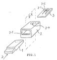
eine schematische perspektivische Darstellung der erfindungsgemäßen Aufnahme-Anordnung;
eine Schnittdarstellung der erfindungsgemäßen Aufnahme-Anordnung für die Schnittebene X-X in FIG.1. In dieser Darstellung ist nur das Einschub-
eine Schnittdarstellung der erfindungsgemäßen Aufnahme-Anordnung für die Schnittebene X-X in FIG.1; in dieser Darstellung sind sowohl das Einschub-
Show it:
a schematic perspective view of the receiving arrangement according to the invention;
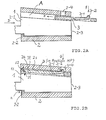
a sectional view of the receiving arrangement according to the invention for the sectional plane XX of FIG.1; in this illustration, the drawer element is completely arranged in the receiving slot, while the spacer element partially protrudes from the receiving slot;
a sectional view of the receiving arrangement according to the invention for the sectional plane XX in FIG.1; in this illustration, the drawer element and the spacer element are completely arranged in the receiving slot; the assembly is in the locked position;
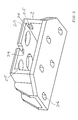
a perspective view of a receiving arrangement according to the invention for a drawer element, which is a hinge leaf of a hinge consisting of 2 hinge leaves;
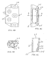
a perspective view of the receiving shaft according to FIG. 3 with oblique viewing direction on the top and in the receiving opening;
the top view of the receiving shaft according to FIG.4A;
the rear side view of the receiving shaft according to FIG. 4A;
the sectional plan view of the receiving shaft according to sectional plane AA in FIG.4A;
a perspective view of the receiving shaft according to FIG. 3 with oblique viewing direction on the underside and in the rear opening;
a perspective view of the receiving shaft according to FIG. 3 with oblique viewing direction on the underside and in the rear opening with protruding distance element;
a perspective view of the
the top view of the spacer according to FIG. 7;
the front view of the spacer according to FIG. 7;
the lower view of the spacer according to FIG. 7;
a perspective view of the drawer element according to FIG. 3 with oblique view on the underside to illustrate its U-profile section.
a schematic perspective view of the receiving arrangement according to the invention;
a sectional view of the receiving arrangement according to the invention for the sectional plane XX in FIG.1. In this illustration, only the
a sectional view of the receiving arrangement according to the invention for the sectional plane XX in FIG.1; In this illustration, both the
In Fig.3 ist eine praktische Ausführungsform der
erfindungsgemäßen Anordnung dargestellt; hier ist zu erkennen,
daß das Einschub-Element 1 Teil eines ersten Scharnierblattes
ist - für ein aus zwei Scharnierblättern 1 und 4 mit einer
gemeinsamen Achse 5 bestehenden Scharnier-. Dieses erste
Scharnierblatt ist in den Aufnahme-Schacht 2 aufnehmbar. Im
Aufnahme-Schacht 2 erfolgt die Verriegelung der Anordnung. Auf
dem Abstands-Element 3 ist ein Federarm 3-1 mit einer Rastnase
3-2 angeordnet, die in Verriegelungs-Position in eine
Aussparung oder Öffnung 2-4 des Aufnahme-Schachtes 2 eingreift.
Das Einschub-Element 1 kann sich dann nicht mehr aus dem
Aufnahme-Schacht 2 lösen. Die Verriegelung ist lösbar.In Fig.3 is a practical embodiment of
Inventive arrangement shown; here you can see
the
Der Aufnahme-Schacht bzw. das zweite Scharnierblatt 4 ist z.B.
durch Schraubverbindungen fest mit einer Gepäck-Box bzw. ihrem
Schwenk-Deckel verbunden.The receiving shaft or the
Das Einschub-Element 1 wird in Einschubrichtung D über die
Schwelle 2-2 hinweg in den Aufnahme-Schacht eingeführt ( s.
FIG. 2A und FIG.3 ).
Im eingeschobenen Zustand des Einschub-Elementes 1 ist zwischen
der oberen Seite 1s des Einschub-Element 1 und der Innenseite
2s des Aufnahme-Schachtes 2 ein Abstandsbereich A ausgebildet.
In diesem Abstandsbereich A ist das Abstands-Element 3
verschieblich angeordnet.
Während des Einführens des Einschub-Elements 1 in den Aufnahme-Schacht
2 ist das Abstands-Element 3 entsprechend der
Darstellung in FIG. 2A positioniert, damit es das Einschub-Element
1 beim Einführen nicht behindern kann.
Danach wird das Abstands-Element 3 in Richtung E bewegt bis es
eine Verriegelungs-Position HP zwischen dem Einschub-Element 1
und der oberen Schachtwandung (FIG. 2B) einnimmt. In dieser
Verriegelungs-Position HP ist das Einschub-Element 1 in seiner
Lage im Aufnahme-Schacht 2 fixiert:
Es (1) kann - wegen der noch später erläuterten Keilwirkung des
keilstumpfförmigen Einschub-Elementes 1 im sich verengenden
Aufnahme-Schacht 2 bzw. wegen des Anschlagens der Randteile 1-2
am Öffnungsrand 2-5, s. FIG. 3, - weder in Richtung D
ausweichen, noch kann es sich entgegengesetzt zur Richtung D
aus dem Schacht 2 bewegen, weil dort die Schwelle 2-2 für die
Stufe 1-1 des Einschub-Elementes 1 als Anschlag wirkt ; und es
kann auch nicht - aufgrund der vertikalen Spiels s=s1+s2 (s.
FIG. 2B) über die Höhe h der Schwelle 2-2 ausweichen, da h>s
ist.
Für andere Ausführungsformen , insbesondere ohne "Keilwirkung"
, kann z.B. auch eine rückwärtige Stirnwand (nicht
dargestellt) im Aufnahme-Schacht als Anschlag dienen.The slide-in
In the inserted state of the
During the insertion of the
Thereafter, the
It can (1) - because of the later explained wedge effect of the wedge-shaped plug-in
For other embodiments, in particular without "wedge effect", for example, a rear end wall (not shown) in the receiving shaft can serve as a stop.
Beim Positionieren des Abstands-Elementes 3 in die
Verriegelungs-Position HP erfolgt eine selbsttätige
Verriegelung:
Das Abstandselement weist einen federnden Arm 3-1 mit einer
Rastnase 3-2 am freien Armende auf.
Bei Bewegung des Abstands-Elementes 3 in Richtung E wird die
Rastnase 3-2 in Richtung F ausgelenkt, sobald sie in den
Aufnahme-Schacht 2 gerät. Wenn die Rastnase 3-2 bei weiterer
Verschiebung des Abstands-Elementes 3 unter die Öffnung 2-4 in
der oberen Wandung des Aufnahme-Schachtes 2 gelangt, rastet sie
- bedingt durch die Federkraft des Armes 3-1 selbsttätig in
diese Öffnung 2-4 ein. Damit ist jedoch die Anordnung
verriegelt. Zur Entriegelung wird die Rastnase 3-2 in Richtung
G ( z.B. mit Hilfe eines Werkzeuges) aus der Öffnung 2-4
gedrückt unter gleichzeitiger Verschiebung des Abstands-Elements. When positioning the
The spacer element has a resilient arm 3-1 with a latching nose 3-2 at the free end of the arm.
When moving the
In einer besonders vorteilhaften Ausführungsform der
erfindungsgemäßen Anordnung weisen das Einschub-Element 1 und
und der Aufnahme-Schacht 2 in Einschubrichtung D eine
abfallende Schräge 1s bzw. 2s auf.
Die Schräge 1s bedingt eine keilstumpfähnliche Form des
Einschub-Elementes. Die sich in Richtung D keilförmig
verjüngende Öffnung des Aufnahme-Schachtes 2 kann
anschlagbegrenzend für das keilstumpfähnliche Einschub-Element
wirken.In a particularly advantageous embodiment of the arrangement according to the invention, the
The slope 1s requires a wedge-like shape of the insert element. The opening in the direction of D wedge-shaped opening of the receiving
Die erfindungsgemäße Anordnung kann sich auf beliebige Querschnitte bzw. Profilquerschnitte des Einschub-Elementes beziehen, egal ob rechteckig, rund oder anders, wobei natürlich der Aufnahme-Schacht an das Einschub-Element angepaßt sein muß, unabhängig davon, ob abfallende Schrägen vorgesehen werden oder nicht.The arrangement according to the invention can be arbitrary Cross sections or profile cross sections of the slide-in element refer, whether rectangular, round or otherwise, being natural the receiving shaft must be adapted to the withdrawable element, regardless of whether sloping slopes are provided or Not.
Ebenso muß für die erfindungsgemäße Anordnung der Abstandsbereich A nicht unbedingt geradlinig abgegrenzt sein; zur Erzielung der Verriegelung können auch andere als nur schieberartige Abstands-Elemente verwendet werden: in diesem Zusammenhang sind alle Elemente geeignet, welche das Einschub-Element im Aufnahme-Schacht in einer Verriegelungs-Position fixieren können. Hierzu zählen auch exzentrisch wirkende oder keilförmige Abstands-Elemente, welche auf das Einschub-Element im Aufnahme-Schacht entweder nur an einer einzigen Stelle oder auch in einem größeren Bereich einwirken, um es in seiner Lage zu fixieren.Likewise, must for the inventive arrangement of Distance range A is not necessarily delimited in a straight line; to achieve the lock, other than just slider-like spacing elements are used: in this In connection all elements are suitable, which are the insertion element in the receiving bay in a locking position can fix. These include eccentric or wedge-shaped spacing elements, which on the slide-in element in the receiving bay either only in a single place or also act in a larger area to it in its location to fix.
Es wurde bereits darauf hingewiesen, daß das Einschub-Element 1
in Verriegelungs-Position HP durch die als Anschlag wirkende
Schwelle 2-3 daran gehindert wird, sich entgegengesetzt zur
Einschub-Richtung D aus dem Aufnahme-Schacht 2 bewegen zu
können. It has already been pointed out that the
Für einen solchen Anschlag kommen auch andere Lösungen in Betracht: z.B. ein mit dem Einschub-Element verbundener Zapfen, welcher in eine Aussparung der Aufnahme-Schacht-Wandung eingreift ( oder umgekehrt), um eine gedachte Bewegung entgegengesetzt zu Richtung D zu verhindern.For such an attack, other solutions come in Consider: e.g. a connected to the drawer element Spigot, which in a recess of the receiving shaft wall engages (or vice versa) to a to prevent imaginary movement opposite to direction D.
Anstelle der beschriebenen Rastverbindung (Rast-nase 3-2 / Öffnung 2-4) können auch andere bekannte Rastverbindungen verwendet werden.Instead of the described latching connection (latching nose 3-2 / Opening 2-4) can also other known locking connections be used.
FIG.3 zeigt
eine perspektische Darstellung einer erfindungsgemäßen
Aufnahme-Anordnung für ein Einschub-Element 1, welches ein
Scharnierblatt eines aus 2 Scharnierblättern 1 und 4
bestehenden Scharniers darstellt.FIG. 3 shows
a perspective view of a receiving arrangement according to the invention for a
Für die in den FIG.1, 2A und 2B nur schematisch dargestellten
Teile ( z.B. Einschub-Element 1, Aufnahme-Schacht 2,
Abstandselement 3 ) zeigt FIG. 3 eine produktspezifische
spezielle Ausführungsform.For those shown in FIGS.1, 2A and 2B only schematically
Parts (e.g., insert
Aus Übersichtsgründen werden in FIG. 3 etc. die Bezugszeichen aus FIG. 1 etc. beibehalten.For clarity, FIG. 3, etc., the reference numerals from FIG. 1 etc. maintained.
Das Einschub-Element 1 hat eine keilstumpf-ähnliche Form bei
einem teilweise U-Profil-ähnlichen Querschnitt ( s. FIG.9).
Auf seiner Oberseite weist es randwärts zwei in D-Richtung
abfallend schräg verlaufende Gleit-Bahnen 1s auf.The
Das Abstands-Element 3 wird durch die Öffnung 2-1 in den
Aufnahme-Schacht 2 eingeführt und in eine Position geschoben,
in welcher es aus einer rückwärtigen Öffnung 2-3 ( s. FIG.4C,
FIG.5) des Aufnahme-Schachtes 2 teilweise heraussteht ( wie in
FIG. 3 dargestellt). Das Abstands-Element hat eine keilartige
Form mit einem sich in Richtung E verjüngenden Querschnitt. The
Das Abstands-Element 3 wird im Aufnahme-Schachtes 2 zwischen
den Führungsbahnen 2-5 (s. FIG. 4C, FIG.4D, FIG. 5 und FIG.6)
geführt.
Ein entsprechende Anschlag 2-6 im Aufnahme-Schacht 2 verhindert
in Verbindung mit dem stufenförmigen Absatz 3-3 am Rand des
Abstands-Elementes 3 (s. FIG.7, 8A und 8C) , daß es (3)
vollends aus der rückwärtigen Öffnung 2-3 des Aufnahme-Schachtes
2 herausgeschoben werden kann.
Beim Einführen des Abstands-Elementes 3 in den Aufnahme-Schacht
in die in FIG. 3 dargestellte Position ist dafür Sorge zu
tragen ( durch Herunterdrücken des Federarmes), daß auf dem
Verschiebungsweg die Rastnase 3-2 nicht in die Öffnung des
Aufnahme-Schachtes eingreifen kann.
Sobald sich das Abstands-Element in der dargestellten Position
(FIG. 3) befindet, kann das Einschub-Element durch die Öffnung
2-1 in den Aufnahme-Schacht 2 eingeführt werden. Dabei wird es
quasi über die Schwelle 2-2 hinwegbewegt, bis schließlich diese
Schwelle 2-2 in die Quernut 1-1 des Einschub-Elementes 1
eingreifen kann.
Ein weiteres Hineinschieben des Einschub-Elementes 1 in den
Aufnahme-Schacht 2 wird dadurch verhindert, daß seine (1) nach
außen stehenden Randteile 1-2 an den Rand 2-5 der Öffnung 2-1
des Aufnahme-Schachtes anschlagen.
In eingeschobener Position des Einschub-Elementes 1 kann nun
das Abstands-Element 3 in Richtung E in den freien Zwischenraum
zwischen der Oberseite 1s des Einschub-Elementes 1 und der
Innenseite 2s der oberen Wandung des Aufnahme-Schachtes
geschoben werden.
Dabei wird die auf dem Federarm 3-1 nach oben stehende Rastnase
3-2 durch die obere Innenseite des Aufnahme-Schachtes 2 nach
unten gedrückt, bis sie bei weiterer Verschiebung des Abstands-Elements
in Richtung E unter die Öffnung 2-4 gerät und dort
einrastet. The
A corresponding stop 2-6 in the receiving
When inserting the
Once the spacer element is in the illustrated position (FIG. 3), the insert element can be inserted through the opening 2-1 into the receiving
Further insertion of the
In the inserted position of the
In this case, on the spring arm 3-1 upstanding locking lug 3-2 is pressed by the upper inside of the receiving
Das Einschub-Element 1 ist - wie bereits erläutert- zugleich
Scharnierblatt eines aus zwei Scharnierblättern 1 und 4 mit
einer gemeinsamen Scharnierachse 5 bestehenden Scharniers.
(FIG.3) .
Die Befestigung des Scharnierblattes z.B. an einem Schwenk-Deckel
oder die Befestigung des Aufnahme-Schachtes 2 an einer
Gepäckbox kann durch Schraubverbindungen o.ä. erfolgen- hierfür
sind die Durchgangslöcher 4-1 bzw. 2-6 vorgesehen.
Die im eingeführten Zustand des Einschub-Elementes 1
aufeinander ausgerichteten Öffnungen M im Aufnahme-Schacht 2
und im Einschub-Element 1 dienen anderen Montagezwecken.The
The attachment of the hinge leaf, for example, on a swivel lid or the attachment of the receiving
The in the imported state of the
FIG. 5 zeigt
eine perspektivische Darstellung des Aufnahme-Schachtes 2
gemäß FIG. 3 mit schräger Blickrichtung auf dessen Unterseite
und in dessen rückwärtige Öffnung 2-3.
Das Abstands-Element 3 (s. FIG.6) ist seitlich zwischen den
Bahnführungen 2-5 angeordnet.FIG. 5 shows
a perspective view of the receiving
The spacer element 3 (see FIG. 6) is arranged laterally between the web guides 2-5.
FIG. 6
eine perspektivische Darstellung des Aufnahme-Schachtes 2 gemäß
FIG. 3 mit schräger Blickrichtung auf dessen Unterseite und in
dessen rückwärtige Öffnung 2-3 mit teilweise herausstehendem
Abstandselement 3.FIG. 6
a perspective view of the receiving
Die in FIG. 5 und FIG.6 verwendeten Bezugszeichen sind die gleichen wie in FIG.3.The in FIG. 5 and FIG.6 are the reference numerals same as in FIG.3.
FIG. 7 zeigt
eine perspektivische Darstellung des Abstandselementes 3 gemäß
FIG. 3;
Es zeigen
FIG. 8A die Drausicht,
FIG. 8B die Vorderansicht und
FIG. 8C die untere Ansicht des Abstands-Elementes. FIG. 7 shows
a perspective view of the
Show it
FIG. 8A the outside,
FIG. 8B the front view and
FIG. 8C is the bottom view of the spacer element.
Die jeweils verwendeten Bezugszeichen sind die gleichen.
Auf die vorstehende Beschreibung wird verwiesen.The respective reference numerals used are the same.
Reference is made to the above description.
FIG.9 zeigt
eine perspektivische Darstellung des Einschub-Elementes 1 gemäß
FIG. 3 mit schräger Blickrichtung auf dessen Unterseite zur
Verdeutlichung seines U-Profil-Abschnittes 9.FIG. 9 shows
a perspective view of the plug-in
Als verwendete Materialien kommen für das Einschub-Element 1
und das Abstands-Element vorzugsweise Kunststoffe, insbesondere
Polyetherimid oder Polyarylamid in Betracht.
Diese Teile sind in diesem Zusammenhang leicht im
Spritzgußverfahren herstellbar.The materials used for the
These parts are easily produced by injection molding in this context.
Die erfindungsgemäße Aufnahme-Anordnung in ihrer
Ausführungsform gemäß FIG. 3 weist insbesondere folgende
Vorteile auf:
schnelle Montage,
hohe Belastbarkeit,
die Rastnase 3-2 wird bei der Verriegelung nicht von den auf
das Einschub-Element wirkenden äußeren Kräften belastet,
gleichbleibende Positionierung des Einschub-Elementes im
Aufnahme-Schacht bei häufigem Entfernen und Wiedereinsetzen des
Einschub-Elementes.The recording arrangement according to the invention in its embodiment according to FIG. 3 has the following advantages in particular:
fast assembly,
high load capacity,
the locking lug 3-2 is not burdened by the external forces acting on the insertion element in the locking, constant positioning of the insertion element in the receiving shaft with frequent removal and replacement of the drawer element.
Claims (12)
dadurch gekennzeichnet daß ein Einschub-Element (1),
ein Aufnahme- Schacht (2) mit einer Einführ-Öffnung (2-1) zur Aufnahme dieses Einschub-Elements (1) in Einschub-Richtung D und ein positionierbares Abstands-Element (3),
vorgesehen sind,
daß
im eingeschobenen Zustand des Einschub-Elementes (1) im Aufnahme-Schacht (2) zwischen dem Einschub-Element (1) und dem Aufnahme-Schacht (2) ein Abstandsbereich (A) ausgebildet ist,
daß das Abstands-Element (3) im Abstandsbereich (A) derart anordnungsbar ist,
daß das Einschub-Element(1) im Aufnahme-Schacht (2) in einer Verriegelungs-Position (HP) fixiert ist,
in welcher es (1) durch einen Anschlag (2-2) an einer Bewegung aus der Einführ-Öffnung (2-1) heraus bzw. in welcher es durch einen Anschlag an einer weiteren Bewegung in Einschubrichtung (D) gehindert ist,
und in welcher das Abstands-Element (3) mit dem Aufnahme-Schacht (2) selbsttätig verriegelbar (2-4/3-2) ist,
und daß diese Verriegelung (2-4/ 3-2) lösbar ist.Arrangement for receiving a releasably lockable insert element,
characterized in that a slide-in element (1),
a receiving shaft (2) having an insertion opening (2-1) for receiving this insertion element (1) in the insertion direction D and a positionable spacing element (3),
are provided
that
in the inserted state of the insertion element (1) in the receiving shaft (2) between the insertion element (1) and the receiving shaft (2) a distance range (A) is formed,
that the spacing element is such anordnungsbar in the distance range (A) (3)
that the slide-in element (1) is fixed in the receiving slot (2) in a locking position (HP),
in which it (1) is prevented from moving out of the insertion opening (2-1) by a stop (2-2) or in which it is prevented from moving further in the insertion direction (D) by a stop,
and in which the spacer element (3) with the receiving shaft (2) is automatically lockable (2-4 / 3-2),
and that this lock (2-4 / 3-2) is releasable.
dadurch gekennzeichnet, daß
das Einschub-Element (1) und der Aufnahme-Schacht (2) in Einschubrichtung (D) eine abfallende Schräge (1s bzw. 2s) aufweisen, wobei der Abstands-Bereich (A) im eingeschobenen Zustand des Einschub-Elementes (1) im Aufnahme-Schacht (2) zwischen der Schacht-Schräge (2S) und der Einschub-Element-Schräge (1S) ausgebildet ist.Arrangement according to claim 1,
characterized in that
the insertion element (1) and the receiving shaft (2) in the insertion direction (D) have a sloping slope (1s or 2s), wherein the distance range (A) in the inserted state of the insertion element (1) in Recording slot (2) between the slot slope (2S) and the insertion-element bevel (1S) is formed.
dadurch gekennzeichnet, daß
der Anschlag (2-2) eine an der Einführ-Öffnung (2-1) des Aufnahme-Schachtes (2) angeordnete Schwelle ist,
und daß das Einschub-Element (1) über die Schwelle (2-2) hinweg in den Aufnahme-Schacht (2) einführbar ist.Arrangement according to claim 1,
characterized in that
the stopper (2-2) is a sill located at the insertion opening (2-1) of the receiving shaft (2),
and that the insertion element (1) over the threshold (2-2) of time in the receiving shaft (2) can be inserted.
dadurch gekennzeichnet, daß
der Aufnahme-Schacht (2) quer zur Einschubrichtung (D) einen rechteckigen Querschnitt,
und daß das Einschub-Element (1) quer zur Einschubrichtung (D) einen rechteckigen Querschnitt oder eine U-Profil-Gestaltung aufweist.Arrangement according to claim 1,
characterized in that
the receiving shaft (2) transversely to the insertion direction (D) has a rectangular cross-section,
and that the insertion element (1) transversely to the insertion direction (D) has a rectangular cross-section or a U-profile design.
dadurch gekennzeichnet, daß das
Abstands-Element(1) im Aufnahme-Schacht (2) verschiebbar angeordnet ist,
daß das Abstands-Element (3) einen Federarm (3-1) mit einer in Richtung der Aufnahme-Schacht-Wandung wirkenden Rastnase (3-2) aufweist,
und daß bei Verschiebung des Abstands-Elementes (3) im Aufnahme-Schacht (2) die Rastnase (3-2) in eine Öffnung (2-4) der Aufnahme-Schacht-Wandung selbsttätig einrastbar ist.Arrangement according to claim 1,
characterized in that the
Distance element (1) slidably disposed in the receiving shaft (2),
the spacer element (3) has a spring arm (3-1) with a latching nose (3-2) acting in the direction of the receiving shaft wall,
and that upon displacement of the distance element (3) in the receiving shaft (2), the latching lug (3-2) in an opening (2-4) of the receiving shaft wall is automatically latched.
dadurch gekennzeichnet, daß
die Rastverbindung (3-2 / 2-4)durch Herausdrücken der Rastnase (3-2) aus der Öffnung (2-4) unter Verschiebung des Abstand-Elementes (3) lösbar ist.Arrangement according to claim 5,
characterized in that
the locking connection (3-2 / 2-4) by pushing out the latching lug (3-2) from the opening (2-4) under displacement of the spacer element (3) is releasable.
dadurch gekennzeichnet, daß
das Abstandselement (3) in seiner Verschieberichtung keilförmig ausgebildet ist.Arrangement according to claim 5,
characterized in that
the spacer element (3) is wedge-shaped in its direction of displacement.
dadurch gekennzeichnet, daß
im Aufnahme-Schacht eine Führungbahn (2-5) für das Abstands-Element (3) vorgesehen ist.Arrangement according to claim 1 or 5,
characterized in that
a guide track (2-5) for the distance element (3) is provided in the receiving slot.
dadurch gekennzeichnet, daß
die Führungsbahn (2-5) im hinteren Teil des Aufnahme-Schachtes (2) an der der Einführ-Öffnung (2-1) abgewandten Seite angeordnet ist.Arrangement according to claim 8,
characterized in that
the guide track (2-5) in the rear part of the receiving shaft (2) is arranged on the side facing away from the insertion opening (2-1).
dadurch gekennzeichnet, daß
das Abstands-Element (3) seitwärts einen Absatz (3-3) aufweist und daß im Aufnahmeschacht (2) ein - eine weitere Verschiebung des Abstands-Elementes in Richtung (D) verhindernder -Anschlag (2-6) für diesen Absatz (3-3) angeordnet ist.Arrangement according to one of claims 1 or 5 to 6,
characterized in that
the spacer element (3) has a shoulder (3-3) laterally and that in the receiving shaft (2) - a further displacement of the distance element in the direction (D) preventing - stop (2-6) for this paragraph (3 -3) is arranged.
dadurch gekennzeichnet, daß das
Einschub-Element (1) am Ende seines Einschub-Bereiches eine stufenförmige Aussparung (1-1) aufweist,
daß der Anschlag (2-2) als Schwelle an der Einführ-Öffnung (2-1) des Aufnahmeschachtes (2) ausgebildet ist,
und daß im eingeschobenen Zustand des Einschub-Elementes (1) im Aufnahme-Schacht (2) die stufenförmige Aussparung(1-1) die Schwelle (2-2) hintergreift.Arrangement according to claim 1,
characterized in that the
Insertion element (1) at the end of its insertion area has a stepped recess (1-1),
the stop (2-2) is formed as a threshold at the insertion opening (2-1) of the receiving shaft (2),
and that in the retracted state of the insertion element (1) in the receiving shaft (2), the stepped recess (1-1) engages behind the threshold (2-2).
dadurch gekennzeichnet, daß
das Einschub-Element (1) am Ende seines Einschub-Bereiches nach außen stehende Vorsprünge (1-2) aufweist, welche im eingeschobenen Zustand des Einschub-Elementes (1) im Aufnahme-Schacht (2) an den Rand (2-5) der Einführ-Öffnung (2-1) des Aufnahme-Schachtes (2) anschlagen.Arrangement according to claim 1,
characterized in that
the insertion element (1) at the end of its insertion area outwardly projecting projections (1-2) which in the inserted state of the insertion element (1) in the receiving shaft (2) to the edge (2-5) engage the insertion opening (2-1) of the receiving shaft (2).
Applications Claiming Priority (2)
| Application Number | Priority Date | Filing Date | Title |
|---|---|---|---|
| DE20308234U | 2003-05-27 | ||
| DE20308234U DE20308234U1 (en) | 2003-05-27 | 2003-05-27 | Arrangement for receiving a releasably lockable insert element |
Publications (3)
| Publication Number | Publication Date |
|---|---|
| EP1482183A2 true EP1482183A2 (en) | 2004-12-01 |
| EP1482183A3 EP1482183A3 (en) | 2006-04-19 |
| EP1482183B1 EP1482183B1 (en) | 2008-05-07 |
Family
ID=27771699
Family Applications (1)
| Application Number | Title | Priority Date | Filing Date |
|---|---|---|---|
| EP04011473A Expired - Lifetime EP1482183B1 (en) | 2003-05-27 | 2004-05-14 | arrangement for retaining a locking and releasable insert element |
Country Status (5)
| Country | Link |
|---|---|
| US (1) | US7524131B2 (en) |
| EP (1) | EP1482183B1 (en) |
| AT (1) | ATE394603T1 (en) |
| CA (1) | CA2466553A1 (en) |
| DE (2) | DE20308234U1 (en) |
Families Citing this family (16)
| Publication number | Priority date | Publication date | Assignee | Title |
|---|---|---|---|---|
| US7346959B2 (en) * | 2004-02-27 | 2008-03-25 | Newell Operating Company | Hinge |
| DE102005060664A1 (en) * | 2005-12-19 | 2007-06-21 | Robert Bosch Gmbh | connecting element |
| DE202005020308U1 (en) * | 2005-12-27 | 2007-05-03 | S-Fasteners Gmbh | decompression |
| DE202005020309U1 (en) * | 2005-12-27 | 2007-05-10 | S-Fasteners Gmbh | Connecting arrangement for superimposed layers of material |
| DE202006004081U1 (en) * | 2006-03-13 | 2007-08-02 | S-Fasterners Gmbh | Arrangement for the detachable attachment of components to a ceiling or wall |
| DE202006019165U1 (en) * | 2006-12-20 | 2008-05-08 | S-Fasteners Gmbh | Arrangement with a locking element for a locking hook |
| DE202007000112U1 (en) * | 2007-01-02 | 2008-05-15 | S-Fasteners Gmbh | Locking arrangement with a pivotable locking hook and a sliding support rod |
| DE202007014471U1 (en) | 2007-10-16 | 2009-03-12 | Sfs Intec Holding Ag | Hinge for a luggage box or the like. |
| DE102008022253A1 (en) * | 2008-05-06 | 2009-11-12 | Miva Technologies Gmbh | High-resolution photoplotting method and arrangement for the high-resolution recording of a computer-stored raster image on a planar photosensitive recording medium |
| FR2934334B1 (en) * | 2008-07-22 | 2012-01-13 | Lisi Automotive Rapid | SYSTEM FOR FIXING A MOBILE PATCH IN A FIXED SLIDER |
| DE202011106316U1 (en) * | 2011-10-05 | 2013-02-01 | Grass Gmbh | Device for a movable furniture part of a furniture with a movable actuator arm and furniture with such a device |
| US9366281B2 (en) * | 2013-11-05 | 2016-06-14 | Delphi Technologies, Inc. | Housing with self-mounting feature |
| DE102015013229A1 (en) * | 2015-10-14 | 2017-04-20 | Rheinisch-Westfälische Technische Hochschule (Rwth) Aachen | Post-beam connection and method of making same |
| CN106419212A (en) * | 2016-10-13 | 2017-02-22 | 广东皇田环保科技有限公司 | Hidden connecting part and furniture |
| US10079015B1 (en) | 2016-12-06 | 2018-09-18 | Amazon Technologies, Inc. | Multi-layer keyword detection |
| KR102279604B1 (en) * | 2020-11-04 | 2021-07-21 | 주식회사 우보테크 | Block type structure for assembling vehicle body |
Family Cites Families (16)
| Publication number | Priority date | Publication date | Assignee | Title |
|---|---|---|---|---|
| US3664011A (en) * | 1969-08-08 | 1972-05-23 | Jacques Guillon Designers Inc | Method of making a joinery joint |
| US3680898A (en) * | 1970-05-25 | 1972-08-01 | Frederick H Herrmann | Furniture joint |
| DE2629781A1 (en) * | 1976-07-02 | 1978-01-05 | Ver Baubeschlag Gretsch Co | Adjustable mounting for movable window fastening - has tapered screw in similar slot between fixed and movable member |
| US4187035A (en) * | 1979-02-14 | 1980-02-05 | Colburn Edward N | Keeper pin system for shovel teeth |
| JPS5749913Y2 (en) * | 1979-09-05 | 1982-11-01 | ||
| US4662531A (en) * | 1986-03-17 | 1987-05-05 | Rca Corporation | Snap-together latch for television cabinet |
| JP2585038Y2 (en) * | 1991-05-29 | 1998-11-11 | 旭光学工業株式会社 | Moving member positioning mechanism |
| DE9110175U1 (en) * | 1991-08-16 | 1991-10-02 | Ferco International, Sarrebourg | Fitting for clamping in a profile groove undercut on at least one side |
| FR2691216B1 (en) * | 1992-05-18 | 1995-12-15 | Landis Gyr Energy Management | CLIP-ON ASSEMBLY DEVICE, WHICH CAN BE MADE UNDETERMINABLE, AND WITH GAME FIXING. |
| DE29516952U1 (en) * | 1995-10-26 | 1997-02-20 | AEG Hausgeräte GmbH, 90429 Nürnberg | Snap connection |
| DE19607786C2 (en) * | 1996-03-01 | 2002-11-21 | Harman Audio Electronic Sys | connecting element |
| CA2179803A1 (en) * | 1996-06-24 | 1997-12-25 | Jerry Wolf | Flexible hinge mechanism |
| GB9727104D0 (en) * | 1997-12-22 | 1998-02-25 | Mckechnie Uk Ltd | Universal latch |
| DE29819377U1 (en) * | 1998-10-30 | 1999-01-28 | Festo AG & Co, 73734 Esslingen | Fastening device |
| CA2295345C (en) * | 1999-03-17 | 2001-11-20 | Peter Ouimet | Connecting device for the cables around a log bundle |
| US20030007831A1 (en) * | 2001-07-06 | 2003-01-09 | Lian Aaron B. | Lock with internal retainer |
-
2003
- 2003-05-27 DE DE20308234U patent/DE20308234U1/en not_active Expired - Lifetime
-
2004
- 2004-05-07 CA CA002466553A patent/CA2466553A1/en not_active Abandoned
- 2004-05-14 DE DE502004007028T patent/DE502004007028D1/en not_active Expired - Lifetime
- 2004-05-14 AT AT04011473T patent/ATE394603T1/en active
- 2004-05-14 EP EP04011473A patent/EP1482183B1/en not_active Expired - Lifetime
- 2004-05-25 US US10/852,214 patent/US7524131B2/en not_active Expired - Fee Related
Also Published As
| Publication number | Publication date |
|---|---|
| ATE394603T1 (en) | 2008-05-15 |
| DE502004007028D1 (en) | 2008-06-19 |
| US7524131B2 (en) | 2009-04-28 |
| DE20308234U1 (en) | 2003-08-21 |
| EP1482183B1 (en) | 2008-05-07 |
| CA2466553A1 (en) | 2004-11-27 |
| US20040240933A1 (en) | 2004-12-02 |
| EP1482183A3 (en) | 2006-04-19 |
Similar Documents
| Publication | Publication Date | Title |
|---|---|---|
| DE69715980T2 (en) | Locking system with rod lock for drawers | |
| EP0421458B1 (en) | Drawer | |
| EP1482183B1 (en) | arrangement for retaining a locking and releasable insert element | |
| DE68914595T2 (en) | Door hinge with quick coupling. | |
| DE20015566U1 (en) | Locking device for a drawer | |
| DE202004015100U1 (en) | Fastening arrangement for the detachable fastening of pull-out guides to drawers | |
| EP1947272A1 (en) | Lock assembly with a swivel latch hook and a movable grip bar for hooking shut | |
| EP3581057A1 (en) | Buckle, in particular a belt buckle | |
| AT500212B1 (en) | DRAWER | |
| EP0178610A2 (en) | Lock | |
| EP0528341A2 (en) | Device for detachably fixing an apparatus housing to a mounting rail | |
| DE202015105093U1 (en) | Pull-out device and furniture | |
| DE202010007430U1 (en) | Device with an attachment device and drawer | |
| EP0255598A2 (en) | Cash drawer | |
| EP3166444B1 (en) | Pull-out guide for a movable furniture part | |
| DE202010014024U1 (en) | Ladder element, in particular for a roof ladder | |
| EP2180283A2 (en) | Receiver for a repeater rifle | |
| EP3569104A2 (en) | Drawer mechanism | |
| DE3607754A1 (en) | Wall-fastening element for panel and compact radiators | |
| DE60007166T2 (en) | COMBINED DRAWER AND DRAWER GUIDE | |
| DE102010013311A1 (en) | Sensor fastening device and associated sensor arrangement | |
| DE202009014693U1 (en) | fitting assembly | |
| DE20220079U1 (en) | When pulling out hard disk containers that do not go wrong | |
| DE102021108249A1 (en) | Coupling element, locking system and furniture | |
| EP1119675B1 (en) | Latch closure |
Legal Events
| Date | Code | Title | Description |
|---|---|---|---|
| PUAI | Public reference made under article 153(3) epc to a published international application that has entered the european phase |
Free format text: ORIGINAL CODE: 0009012 |
|
| AK | Designated contracting states |
Kind code of ref document: A2 Designated state(s): AT BE BG CH CY CZ DE DK EE ES FI FR GB GR HU IE IT LI LU MC NL PL PT RO SE SI SK TR |
|
| AX | Request for extension of the european patent |
Extension state: AL HR LT LV MK |
|
| RIN1 | Information on inventor provided before grant (corrected) |
Inventor name: HOMNER, BERNHARD Inventor name: SCHWARZ, HELMUT |
|
| PUAL | Search report despatched |
Free format text: ORIGINAL CODE: 0009013 |
|
| AK | Designated contracting states |
Kind code of ref document: A3 Designated state(s): AT BE BG CH CY CZ DE DK EE ES FI FR GB GR HU IE IT LI LU MC NL PL PT RO SE SI SK TR |
|
| AX | Request for extension of the european patent |
Extension state: AL HR LT LV MK |
|
| 17P | Request for examination filed |
Effective date: 20060824 |
|
| AKX | Designation fees paid |
Designated state(s): AT DE ES FR GB |
|
| RAP1 | Party data changed (applicant data changed or rights of an application transferred) |
Owner name: SFS INTEC HOLDING AG |
|
| GRAP | Despatch of communication of intention to grant a patent |
Free format text: ORIGINAL CODE: EPIDOSNIGR1 |
|
| GRAS | Grant fee paid |
Free format text: ORIGINAL CODE: EPIDOSNIGR3 |
|
| GRAA | (expected) grant |
Free format text: ORIGINAL CODE: 0009210 |
|
| REG | Reference to a national code |
Ref country code: DE Ref legal event code: R081 Ref document number: 502004007028 Country of ref document: DE Owner name: SFS INTEC HOLDING AG, CH Free format text: FORMER OWNER: SCHWARZ VERBINDUNGS-SYSTEME GMBH, 75382 ALTHENGSTETT, DE |
|
| AK | Designated contracting states |
Kind code of ref document: B1 Designated state(s): AT DE ES FR GB |
|
| REG | Reference to a national code |
Ref country code: GB Ref legal event code: FG4D Free format text: NOT ENGLISH |
|
| REF | Corresponds to: |
Ref document number: 502004007028 Country of ref document: DE Date of ref document: 20080619 Kind code of ref document: P |
|
| REG | Reference to a national code |
Ref country code: DE Ref legal event code: R096 Ref document number: 502004007028 Country of ref document: DE Effective date: 20080619 |
|
| PG25 | Lapsed in a contracting state [announced via postgrant information from national office to epo] |
Ref country code: ES Free format text: LAPSE BECAUSE OF FAILURE TO SUBMIT A TRANSLATION OF THE DESCRIPTION OR TO PAY THE FEE WITHIN THE PRESCRIBED TIME-LIMIT Effective date: 20080818 |
|
| PLBE | No opposition filed within time limit |
Free format text: ORIGINAL CODE: 0009261 |
|
| STAA | Information on the status of an ep patent application or granted ep patent |
Free format text: STATUS: NO OPPOSITION FILED WITHIN TIME LIMIT |
|
| 26N | No opposition filed |
Effective date: 20090210 |
|
| GBPC | Gb: european patent ceased through non-payment of renewal fee |
Effective date: 20080807 |
|
| REG | Reference to a national code |
Ref country code: DE Ref legal event code: R097 Ref document number: 502004007028 Country of ref document: DE Effective date: 20090210 |
|
| PG25 | Lapsed in a contracting state [announced via postgrant information from national office to epo] |
Ref country code: GB Free format text: LAPSE BECAUSE OF NON-PAYMENT OF DUE FEES Effective date: 20080807 |
|
| REG | Reference to a national code |
Ref country code: DE Ref legal event code: R082 Ref document number: 502004007028 Country of ref document: DE Representative=s name: SCHUMACHER & WILLSAU PATENTANWALTSGESELLSCHAFT, DE |
|
| REG | Reference to a national code |
Ref country code: FR Ref legal event code: PLFP Year of fee payment: 13 |
|
| REG | Reference to a national code |
Ref country code: FR Ref legal event code: PLFP Year of fee payment: 14 |
|
| REG | Reference to a national code |
Ref country code: FR Ref legal event code: PLFP Year of fee payment: 15 |
|
| PGFP | Annual fee paid to national office [announced via postgrant information from national office to epo] |
Ref country code: DE Payment date: 20200525 Year of fee payment: 17 Ref country code: FR Payment date: 20200519 Year of fee payment: 17 |
|
| PGFP | Annual fee paid to national office [announced via postgrant information from national office to epo] |
Ref country code: AT Payment date: 20200515 Year of fee payment: 17 |
|
| REG | Reference to a national code |
Ref country code: DE Ref legal event code: R119 Ref document number: 502004007028 Country of ref document: DE |
|
| REG | Reference to a national code |
Ref country code: AT Ref legal event code: MM01 Ref document number: 394603 Country of ref document: AT Kind code of ref document: T Effective date: 20210514 |
|
| PG25 | Lapsed in a contracting state [announced via postgrant information from national office to epo] |
Ref country code: AT Free format text: LAPSE BECAUSE OF NON-PAYMENT OF DUE FEES Effective date: 20210514 |
|
| PG25 | Lapsed in a contracting state [announced via postgrant information from national office to epo] |
Ref country code: DE Free format text: LAPSE BECAUSE OF NON-PAYMENT OF DUE FEES Effective date: 20211201 |
|
| PG25 | Lapsed in a contracting state [announced via postgrant information from national office to epo] |
Ref country code: FR Free format text: LAPSE BECAUSE OF NON-PAYMENT OF DUE FEES Effective date: 20210531 |
|
| P01 | Opt-out of the competence of the unified patent court (upc) registered |
Effective date: 20230622 |