EP1482183A2 - dispositif pour recevoir un insert verrouillable et détachable - Google Patents
dispositif pour recevoir un insert verrouillable et détachable Download PDFInfo
- Publication number
- EP1482183A2 EP1482183A2 EP04011473A EP04011473A EP1482183A2 EP 1482183 A2 EP1482183 A2 EP 1482183A2 EP 04011473 A EP04011473 A EP 04011473A EP 04011473 A EP04011473 A EP 04011473A EP 1482183 A2 EP1482183 A2 EP 1482183A2
- Authority
- EP
- European Patent Office
- Prior art keywords
- receiving shaft
- receiving
- arrangement according
- opening
- distance
- Prior art date
- Legal status (The legal status is an assumption and is not a legal conclusion. Google has not performed a legal analysis and makes no representation as to the accuracy of the status listed.)
- Granted
Links
Images


Classifications
-
- F—MECHANICAL ENGINEERING; LIGHTING; HEATING; WEAPONS; BLASTING
- F16—ENGINEERING ELEMENTS AND UNITS; GENERAL MEASURES FOR PRODUCING AND MAINTAINING EFFECTIVE FUNCTIONING OF MACHINES OR INSTALLATIONS; THERMAL INSULATION IN GENERAL
- F16B—DEVICES FOR FASTENING OR SECURING CONSTRUCTIONAL ELEMENTS OR MACHINE PARTS TOGETHER, e.g. NAILS, BOLTS, CIRCLIPS, CLAMPS, CLIPS OR WEDGES; JOINTS OR JOINTING
- F16B2/00—Friction-grip releasable fastenings
- F16B2/02—Clamps, i.e. with gripping action effected by positive means other than the inherent resistance to deformation of the material of the fastening
- F16B2/14—Clamps, i.e. with gripping action effected by positive means other than the inherent resistance to deformation of the material of the fastening using wedges
-
- F—MECHANICAL ENGINEERING; LIGHTING; HEATING; WEAPONS; BLASTING
- F16—ENGINEERING ELEMENTS AND UNITS; GENERAL MEASURES FOR PRODUCING AND MAINTAINING EFFECTIVE FUNCTIONING OF MACHINES OR INSTALLATIONS; THERMAL INSULATION IN GENERAL
- F16B—DEVICES FOR FASTENING OR SECURING CONSTRUCTIONAL ELEMENTS OR MACHINE PARTS TOGETHER, e.g. NAILS, BOLTS, CIRCLIPS, CLAMPS, CLIPS OR WEDGES; JOINTS OR JOINTING
- F16B2200/00—Constructional details of connections not covered for in other groups of this subclass
- F16B2200/69—Redundant disconnection blocking means
- F16B2200/71—Blocking disengagement of catches or keys
-
- Y—GENERAL TAGGING OF NEW TECHNOLOGICAL DEVELOPMENTS; GENERAL TAGGING OF CROSS-SECTIONAL TECHNOLOGIES SPANNING OVER SEVERAL SECTIONS OF THE IPC; TECHNICAL SUBJECTS COVERED BY FORMER USPC CROSS-REFERENCE ART COLLECTIONS [XRACs] AND DIGESTS
- Y10—TECHNICAL SUBJECTS COVERED BY FORMER USPC
- Y10T—TECHNICAL SUBJECTS COVERED BY FORMER US CLASSIFICATION
- Y10T24/00—Buckles, buttons, clasps, etc.
- Y10T24/45—Separable-fastener or required component thereof [e.g., projection and cavity to complete interlock]
- Y10T24/45005—Separable-fastener or required component thereof [e.g., projection and cavity to complete interlock] with third detached member completing interlock [e.g., hook type]
- Y10T24/45099—Resilient element [e.g., snap type]
-
- Y—GENERAL TAGGING OF NEW TECHNOLOGICAL DEVELOPMENTS; GENERAL TAGGING OF CROSS-SECTIONAL TECHNOLOGIES SPANNING OVER SEVERAL SECTIONS OF THE IPC; TECHNICAL SUBJECTS COVERED BY FORMER USPC CROSS-REFERENCE ART COLLECTIONS [XRACs] AND DIGESTS
- Y10—TECHNICAL SUBJECTS COVERED BY FORMER USPC
- Y10T—TECHNICAL SUBJECTS COVERED BY FORMER US CLASSIFICATION
- Y10T403/00—Joints and connections
- Y10T403/60—Biased catch or latch
- Y10T403/606—Leaf spring
Definitions
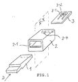
- the invention relates to a releasable connection arrangement in which a slide-in element is detachably connected to a receiving shaft. Insertion element and receiving shaft can be connected to one component or even represent such a component.
- connection arrangements There are a large number of such often very differently designed connection arrangements known: For example, so-called bayonet locks, according to the "" drawer principle "working connection arrangements, etc. All of these arrangements satisfy special purpose tasks. It is an object of the invention to provide a new detachable connection arrangement in which a drawer element with a receiving slot in a constant position is detachably connected. This object of the invention is achieved by the features mentioned in the characterizing part of claim 1. Advantageous developments of the invention are characterized in the subclaims.
- hinge connections can be used, in which, for example, a swivel lid must be removed from a luggage box temporarily temporarily (eg for maintenance work in aircraft).
- a swivel lid must be removed from a luggage box temporarily temporarily (eg for maintenance work in aircraft).
- pivot lid and luggage box are firmly connected to the hinge leaves, for example by screwing or riveting.
- the hinge leaf to be connected to the luggage box is designed as a plug-in part (plug-in element); It is inserted into a receiving slot firmly connected to the luggage box and fixed there in a special way in its position, automatically locking takes place.
- the lock is detachable.
- the swivel cover can always be easily detached from the luggage box. This is necessary if appropriate maintenance (eg in the aircraft) are pending, in which the pivot cover must be temporarily removed (because he would otherwise hinder the maintenance of space reasons.
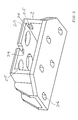
- Fig.3 is a practical embodiment of Inventive arrangement shown; here you can see the insertion element 1 is part of a first hinge leaf is - for one of two hinges 1 and 4 with a common axis 5 existing hinge. This first Hinge leaf is in the receiving slot 2 receivable. in the Recording slot 2, the locking of the arrangement takes place. On the distance element 3 is a spring arm 3-1 with a locking lug 3-2 arranged in the locking position in a Recess or opening 2-4 of the receiving shaft 2 engages. The drawer element 1 can then no longer from the Release take-up shaft 2. The lock is detachable.
- the receiving shaft or the second hinge leaf 4 is e.g. by screw firmly with a luggage box or her Pivoting lid connected.
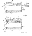
- the slide-in element 1 is inserted in the insertion direction D across the threshold 2-2 into the receiving shaft (see FIGS. 2A and 3).
- a distance range A is formed between the upper side 1s of the insertion element 1 and the inner side 2s of the receiving shaft 2.
- the distance element 3 is arranged displaceably.
- the distance element 3 as shown in FIG. 2A positioned so that it can not hinder the insertion element 1 during insertion.
- the distance element 3 is moved in the direction E until it assumes a locking position HP between the insertion element 1 and the upper shaft wall (FIG. 2B).
- the insertion element 1 In this locking position HP, the insertion element 1 is fixed in its position in the receiving shaft 2: It can (1) - because of the later explained wedge effect of the wedge-shaped plug-in element 1 in the narrowing receiving shaft 2 or because of the striking of the edge parts 1-2 at the opening edge 2-5, s.
- a rear end wall (not shown) in the receiving shaft can serve as a stop.
- the spacer element has a resilient arm 3-1 with a latching nose 3-2 at the free end of the arm.
- the locking lug 3-2 is deflected in the direction F as soon as it gets into the receiving shaft 2.
- the locking lug 3-2 passes on further displacement of the spacer element 3 under the opening 2-4 in the upper wall of the receiving shaft 2, it locks - due to the spring force of the arm 3-1 automatically in this opening 2-4 one. This, however, the arrangement is locked.
- To unlock the locking lug 3-2 in direction G (eg with the aid of a tool) from the opening 2-4 is pressed with simultaneous displacement of the distance element.
- the slope 1s requires a wedge-like shape of the insert element.
- the opening in the direction of D wedge-shaped opening of the receiving shaft 2 can stop limiting act for the wedge-like plug-in element.
- the arrangement according to the invention can be arbitrary Cross sections or profile cross sections of the slide-in element refer, whether rectangular, round or otherwise, being natural the receiving shaft must be adapted to the withdrawable element, regardless of whether sloping slopes are provided or Not.
- latching connection latching nose 3-2 / Opening 2-4
- latching nose 3-2 / Opening 2-4 latching nose 3-2 / Opening 2-4
- FIG. 3 shows a perspective view of a receiving arrangement according to the invention for a drawer element 1, which is a hinge leaf of a hinge consisting of 2 hinge leaves 1 and 4.
- FIGS.1, 2A and 2B only schematically Parts (e.g., insert element 1, receptacle 2, Spacer element 3) is shown in FIG. 3 a product specific special embodiment.
- FIG. 3 etc. the reference numerals from FIG. 1 etc. maintained.
- the insert element 1 has a wedge-like shape a partially U-profile-like cross-section (see FIG.9). On its upper side, it has two edges in the D direction sloping sloping sliding tracks 1s on.
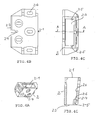
- the spacer element 3 is inserted through the opening 2-1 in the Inserted receiving shaft 2 and pushed into a position, in which it consists of a rear opening 2-3 (see FIG.4C, FIG.5) of the receiving shaft 2 partially protrudes (as in FIG. 3).
- the spacer element has a wedge-like Shape with a tapered in direction E cross-section.
- the spacer element 3 is guided in the receiving shaft 2 between the guideways 2-5 (see FIG 4C, FIG.4D, FIG 5 and FIG.6).
- a corresponding stop 2-6 in the receiving shaft 2 prevents in connection with the step-shaped paragraph 3-3 at the edge of the distance element 3 (see Figures 7, 8A and 8C), that it (3) completely from the rear opening 2-3 of the receiving shaft 2 can be pushed out.
- the locking lug 3-2 can not engage in the opening of the receiving shaft.
- the insertion element 1 is - as already explained - at the same hinge leaf of a two hinge leaves 1 and 4 with a common hinge axis 5 existing hinge. (FIG. 3).
- the attachment of the hinge leaf for example, on a swivel lid or the attachment of the receiving shaft 2 to a luggage box or the like by screw. for this purpose, the through holes 4-1 and 2-6 are provided.
- the in the imported state of the drawer element 1 aligned openings M in the receiving slot 2 and in the insertion element 1 serve other mounting purposes.
- FIG. 5 shows a perspective view of the receiving shaft 2 according to FIG. 3 with oblique view on the underside and in the rear opening 2-3.
- the spacer element 3 (see FIG. 6) is arranged laterally between the web guides 2-5.
- FIG. 6 a perspective view of the receiving shaft 2 according to FIG. 3 with oblique viewing direction on the underside and in the rear opening 2-3 with partially protruding spacer.
- FIG. 5 and FIG.6 are the reference numerals same as in FIG.3.
- FIG. 7 shows a perspective view of the spacer 3 according to FIG. 3; Show it FIG. 8A the outside, FIG. 8B the front view and FIG. 8C is the bottom view of the spacer element.
- FIG. 9 shows a perspective view of the plug-in element 1 according to FIG. 3 with oblique view on the underside to illustrate its U-profile section. 9
- the materials used for the insertion element 1 and the spacer element are preferably plastics, in particular polyetherimide or polyarylamide. These parts are easily produced by injection molding in this context.
- the recording arrangement according to the invention in its embodiment according to FIG. 3 has the following advantages in particular: fast assembly, high load capacity, the locking lug 3-2 is not burdened by the external forces acting on the insertion element in the locking, constant positioning of the insertion element in the receiving shaft with frequent removal and replacement of the drawer element.
Landscapes
- Engineering & Computer Science (AREA)
- General Engineering & Computer Science (AREA)
- Mechanical Engineering (AREA)
- Connection Of Plates (AREA)
- Hinges (AREA)
- Details Of Connecting Devices For Male And Female Coupling (AREA)
- Connector Housings Or Holding Contact Members (AREA)
- Orthopedics, Nursing, And Contraception (AREA)
- Snaps, Bayonet Connections, Set Pins, And Snap Rings (AREA)
- Pivots And Pivotal Connections (AREA)
Applications Claiming Priority (2)
| Application Number | Priority Date | Filing Date | Title |
|---|---|---|---|
| DE20308234U DE20308234U1 (de) | 2003-05-27 | 2003-05-27 | Anordnung zur Aufnahme eines lösbar verriegelbaren Einschub-Elementes |
| DE20308234U | 2003-05-27 |
Publications (3)
| Publication Number | Publication Date |
|---|---|
| EP1482183A2 true EP1482183A2 (fr) | 2004-12-01 |
| EP1482183A3 EP1482183A3 (fr) | 2006-04-19 |
| EP1482183B1 EP1482183B1 (fr) | 2008-05-07 |
Family
ID=27771699
Family Applications (1)
| Application Number | Title | Priority Date | Filing Date |
|---|---|---|---|
| EP04011473A Expired - Lifetime EP1482183B1 (fr) | 2003-05-27 | 2004-05-14 | dispositif pour recevoir un insert verrouillable et détachable |
Country Status (5)
| Country | Link |
|---|---|
| US (1) | US7524131B2 (fr) |
| EP (1) | EP1482183B1 (fr) |
| AT (1) | ATE394603T1 (fr) |
| CA (1) | CA2466553A1 (fr) |
| DE (2) | DE20308234U1 (fr) |
Families Citing this family (16)
| Publication number | Priority date | Publication date | Assignee | Title |
|---|---|---|---|---|
| US7346959B2 (en) * | 2004-02-27 | 2008-03-25 | Newell Operating Company | Hinge |
| DE102005060664A1 (de) * | 2005-12-19 | 2007-06-21 | Robert Bosch Gmbh | Anschlusselement |
| DE202005020308U1 (de) * | 2005-12-27 | 2007-05-03 | S-Fasteners Gmbh | Dekompressionsverschluß |
| DE202005020309U1 (de) * | 2005-12-27 | 2007-05-10 | S-Fasteners Gmbh | Verbindungsanordnung für übereinanderliegende Materialschichten |
| DE202006004081U1 (de) * | 2006-03-13 | 2007-08-02 | S-Fasterners Gmbh | Anordnung zur lösbaren Befestigung von Bauteilen an einer Decke oder Wand |
| DE202006019165U1 (de) * | 2006-12-20 | 2008-05-08 | S-Fasteners Gmbh | Anordnung mit einem Verriegelungs-Element für einen Verriegelungshaken |
| DE202007000112U1 (de) * | 2007-01-02 | 2008-05-15 | S-Fasteners Gmbh | Verriegelungsanordnung mit einem schwenkbaren Verriegelungshaken und einer verschiebbaren Haltestange |
| DE202007014471U1 (de) | 2007-10-16 | 2009-03-12 | Sfs Intec Holding Ag | Scharnier für eine Gepäckbox o.dgl. |
| DE102008022253A1 (de) * | 2008-05-06 | 2009-11-12 | Miva Technologies Gmbh | Hochauflösendes Fotoplottverfahren und Anordnung zur hochauflösenden Aufzeichnung eines computergespeicherten Rasterbildes auf einen ebenen lichtempfindlichen Aufzeichnungsträger |
| FR2934334B1 (fr) * | 2008-07-22 | 2012-01-13 | Lisi Automotive Rapid | Systeme de fixation d'une patte mobile dans une coulisse fixe |
| DE202011106316U1 (de) * | 2011-10-05 | 2013-02-01 | Grass Gmbh | Vorrichtung für ein bewegliches Möbelteil eines Möbels mit einem bewegbaren Stellarm sowie Möbel mit einer solchen Vorrichtung |
| US9366281B2 (en) * | 2013-11-05 | 2016-06-14 | Delphi Technologies, Inc. | Housing with self-mounting feature |
| DE102015013229A1 (de) * | 2015-10-14 | 2017-04-20 | Rheinisch-Westfälische Technische Hochschule (Rwth) Aachen | Pfosten-Träger-Verbindung und Verfahren zu deren Herstellung |
| CN106419212A (zh) * | 2016-10-13 | 2017-02-22 | 广东皇田环保科技有限公司 | 隐藏式连接件及家具 |
| US10079015B1 (en) | 2016-12-06 | 2018-09-18 | Amazon Technologies, Inc. | Multi-layer keyword detection |
| KR102279604B1 (ko) * | 2020-11-04 | 2021-07-21 | 주식회사 우보테크 | 블록타입 차체조립구조 |
Family Cites Families (16)
| Publication number | Priority date | Publication date | Assignee | Title |
|---|---|---|---|---|
| US3664011A (en) * | 1969-08-08 | 1972-05-23 | Jacques Guillon Designers Inc | Method of making a joinery joint |
| US3680898A (en) * | 1970-05-25 | 1972-08-01 | Frederick H Herrmann | Furniture joint |
| DE2629781A1 (de) * | 1976-07-02 | 1978-01-05 | Ver Baubeschlag Gretsch Co | Anordnung zur verbindung von teilen |
| US4187035A (en) * | 1979-02-14 | 1980-02-05 | Colburn Edward N | Keeper pin system for shovel teeth |
| JPS5749913Y2 (fr) * | 1979-09-05 | 1982-11-01 | ||
| US4662531A (en) * | 1986-03-17 | 1987-05-05 | Rca Corporation | Snap-together latch for television cabinet |
| JP2585038Y2 (ja) * | 1991-05-29 | 1998-11-11 | 旭光学工業株式会社 | 移動部材の位置決め機構 |
| DE9110175U1 (de) * | 1991-08-16 | 1991-10-02 | Ferco International, Sarrebourg | Beschlagteil zur Klemmbefestigung in einer mindestens einseitig hinterschnittenen Profilnut |
| FR2691216B1 (fr) * | 1992-05-18 | 1995-12-15 | Landis Gyr Energy Management | Dispositif d'assemblage par clipsage, pouvant etre rendu indemontable, et avec rattrapage de jeu. |
| DE29516952U1 (de) * | 1995-10-26 | 1997-02-20 | AEG Hausgeräte GmbH, 90429 Nürnberg | Rastverbindung |
| DE19607786C2 (de) * | 1996-03-01 | 2002-11-21 | Harman Audio Electronic Sys | Verbindungselement |
| CA2179803A1 (fr) * | 1996-06-24 | 1997-12-25 | Jerry Wolf | Mecanisme a charniere souple |
| GB9727104D0 (en) * | 1997-12-22 | 1998-02-25 | Mckechnie Uk Ltd | Universal latch |
| DE29819377U1 (de) * | 1998-10-30 | 1999-01-28 | Festo AG & Co, 73734 Esslingen | Befestigungsvorrichtung |
| CA2295345C (fr) * | 1999-03-17 | 2001-11-20 | Peter Ouimet | Dispositif de bottelage par cables |
| US20030007831A1 (en) * | 2001-07-06 | 2003-01-09 | Lian Aaron B. | Lock with internal retainer |
-
2003
- 2003-05-27 DE DE20308234U patent/DE20308234U1/de not_active Expired - Lifetime
-
2004
- 2004-05-07 CA CA002466553A patent/CA2466553A1/fr not_active Abandoned
- 2004-05-14 DE DE502004007028T patent/DE502004007028D1/de not_active Expired - Lifetime
- 2004-05-14 EP EP04011473A patent/EP1482183B1/fr not_active Expired - Lifetime
- 2004-05-14 AT AT04011473T patent/ATE394603T1/de active
- 2004-05-25 US US10/852,214 patent/US7524131B2/en not_active Expired - Fee Related
Also Published As
| Publication number | Publication date |
|---|---|
| EP1482183B1 (fr) | 2008-05-07 |
| ATE394603T1 (de) | 2008-05-15 |
| CA2466553A1 (fr) | 2004-11-27 |
| EP1482183A3 (fr) | 2006-04-19 |
| DE20308234U1 (de) | 2003-08-21 |
| US7524131B2 (en) | 2009-04-28 |
| US20040240933A1 (en) | 2004-12-02 |
| DE502004007028D1 (de) | 2008-06-19 |
Similar Documents
| Publication | Publication Date | Title |
|---|---|---|
| DE69715980T2 (de) | Verriegelungssystem mit Stangenverschluss für Schubladen | |
| EP1482183B1 (fr) | dispositif pour recevoir un insert verrouillable et détachable | |
| DE68914595T2 (de) | Türscharnier mit Schnellkupplung. | |
| DE20015566U1 (de) | Verriegelungsvorrichtung für eine Schublade | |
| DE2941008B1 (de) | Gestell | |
| DE202004015100U1 (de) | Befestigungsanordnung für die lösbare Befestigung von Ausziehführungen an Schubladen | |
| EP1947272A1 (fr) | Agencement de verrouillage doté d'un crochet de verrouillage articulé et d'une tige de retenue mobile destinée à accrocher | |
| EP3581057A1 (fr) | Boucle, en particulier boucle de ceinture | |
| AT500212B1 (de) | Schublade | |
| EP0178610A2 (fr) | Serrure | |
| DE4127252A1 (de) | Vorrichtung zur loesbaren befestigung eines geraetegehaeuses an einer profilschiene | |
| DE202015105093U1 (de) | Ausziehsperrvorrichtung und Möbel | |
| DE202010007430U1 (de) | Vorrichtung mit einer Anbringeinrichtung und Schublade | |
| EP0255598A2 (fr) | Tiroir de caisse | |
| EP3773074B1 (fr) | Systeme de tiroir comprenant un rail sur lequel differents types de tiroirs peuvent etre installes | |
| EP3166444B1 (fr) | Guidage télescopique pour une partie de meuble mobile | |
| DE202010014024U1 (de) | Leiterelement, insbesondere für eine Dachleiter | |
| EP2180283A2 (fr) | Boîte de culasse pour fusil à répétition | |
| EP3569104A2 (fr) | Glissiere de tiroir | |
| DE3607754A1 (de) | Wandbefestigungselement fuer flaechen- und kompaktheizkoerper | |
| DE60007166T2 (de) | Kombinierte schublade und schubladenführung | |
| DE102010013311A1 (de) | Sensor-Befestigungseinrichtung und zugehörige Sensoranordnung | |
| DE202009014693U1 (de) | Beschlaganordnung | |
| DE20220079U1 (de) | Beim Herausziehen nicht schief gehender Festplattenbehälter | |
| DE102007009667B4 (de) | Profilkonstruktion |
Legal Events
| Date | Code | Title | Description |
|---|---|---|---|
| PUAI | Public reference made under article 153(3) epc to a published international application that has entered the european phase |
Free format text: ORIGINAL CODE: 0009012 |
|
| AK | Designated contracting states |
Kind code of ref document: A2 Designated state(s): AT BE BG CH CY CZ DE DK EE ES FI FR GB GR HU IE IT LI LU MC NL PL PT RO SE SI SK TR |
|
| AX | Request for extension of the european patent |
Extension state: AL HR LT LV MK |
|
| RIN1 | Information on inventor provided before grant (corrected) |
Inventor name: HOMNER, BERNHARD Inventor name: SCHWARZ, HELMUT |
|
| PUAL | Search report despatched |
Free format text: ORIGINAL CODE: 0009013 |
|
| AK | Designated contracting states |
Kind code of ref document: A3 Designated state(s): AT BE BG CH CY CZ DE DK EE ES FI FR GB GR HU IE IT LI LU MC NL PL PT RO SE SI SK TR |
|
| AX | Request for extension of the european patent |
Extension state: AL HR LT LV MK |
|
| 17P | Request for examination filed |
Effective date: 20060824 |
|
| AKX | Designation fees paid |
Designated state(s): AT DE ES FR GB |
|
| RAP1 | Party data changed (applicant data changed or rights of an application transferred) |
Owner name: SFS INTEC HOLDING AG |
|
| GRAP | Despatch of communication of intention to grant a patent |
Free format text: ORIGINAL CODE: EPIDOSNIGR1 |
|
| GRAS | Grant fee paid |
Free format text: ORIGINAL CODE: EPIDOSNIGR3 |
|
| GRAA | (expected) grant |
Free format text: ORIGINAL CODE: 0009210 |
|
| REG | Reference to a national code |
Ref country code: DE Ref legal event code: R081 Ref document number: 502004007028 Country of ref document: DE Owner name: SFS INTEC HOLDING AG, CH Free format text: FORMER OWNER: SCHWARZ VERBINDUNGS-SYSTEME GMBH, 75382 ALTHENGSTETT, DE |
|
| AK | Designated contracting states |
Kind code of ref document: B1 Designated state(s): AT DE ES FR GB |
|
| REG | Reference to a national code |
Ref country code: GB Ref legal event code: FG4D Free format text: NOT ENGLISH |
|
| REF | Corresponds to: |
Ref document number: 502004007028 Country of ref document: DE Date of ref document: 20080619 Kind code of ref document: P |
|
| REG | Reference to a national code |
Ref country code: DE Ref legal event code: R096 Ref document number: 502004007028 Country of ref document: DE Effective date: 20080619 |
|
| PG25 | Lapsed in a contracting state [announced via postgrant information from national office to epo] |
Ref country code: ES Free format text: LAPSE BECAUSE OF FAILURE TO SUBMIT A TRANSLATION OF THE DESCRIPTION OR TO PAY THE FEE WITHIN THE PRESCRIBED TIME-LIMIT Effective date: 20080818 |
|
| PLBE | No opposition filed within time limit |
Free format text: ORIGINAL CODE: 0009261 |
|
| STAA | Information on the status of an ep patent application or granted ep patent |
Free format text: STATUS: NO OPPOSITION FILED WITHIN TIME LIMIT |
|
| 26N | No opposition filed |
Effective date: 20090210 |
|
| GBPC | Gb: european patent ceased through non-payment of renewal fee |
Effective date: 20080807 |
|
| REG | Reference to a national code |
Ref country code: DE Ref legal event code: R097 Ref document number: 502004007028 Country of ref document: DE Effective date: 20090210 |
|
| PG25 | Lapsed in a contracting state [announced via postgrant information from national office to epo] |
Ref country code: GB Free format text: LAPSE BECAUSE OF NON-PAYMENT OF DUE FEES Effective date: 20080807 |
|
| REG | Reference to a national code |
Ref country code: DE Ref legal event code: R082 Ref document number: 502004007028 Country of ref document: DE Representative=s name: SCHUMACHER & WILLSAU PATENTANWALTSGESELLSCHAFT, DE |
|
| REG | Reference to a national code |
Ref country code: FR Ref legal event code: PLFP Year of fee payment: 13 |
|
| REG | Reference to a national code |
Ref country code: FR Ref legal event code: PLFP Year of fee payment: 14 |
|
| REG | Reference to a national code |
Ref country code: FR Ref legal event code: PLFP Year of fee payment: 15 |
|
| PGFP | Annual fee paid to national office [announced via postgrant information from national office to epo] |
Ref country code: DE Payment date: 20200525 Year of fee payment: 17 Ref country code: FR Payment date: 20200519 Year of fee payment: 17 |
|
| PGFP | Annual fee paid to national office [announced via postgrant information from national office to epo] |
Ref country code: AT Payment date: 20200515 Year of fee payment: 17 |
|
| REG | Reference to a national code |
Ref country code: DE Ref legal event code: R119 Ref document number: 502004007028 Country of ref document: DE |
|
| REG | Reference to a national code |
Ref country code: AT Ref legal event code: MM01 Ref document number: 394603 Country of ref document: AT Kind code of ref document: T Effective date: 20210514 |
|
| PG25 | Lapsed in a contracting state [announced via postgrant information from national office to epo] |
Ref country code: AT Free format text: LAPSE BECAUSE OF NON-PAYMENT OF DUE FEES Effective date: 20210514 |
|
| PG25 | Lapsed in a contracting state [announced via postgrant information from national office to epo] |
Ref country code: DE Free format text: LAPSE BECAUSE OF NON-PAYMENT OF DUE FEES Effective date: 20211201 |
|
| PG25 | Lapsed in a contracting state [announced via postgrant information from national office to epo] |
Ref country code: FR Free format text: LAPSE BECAUSE OF NON-PAYMENT OF DUE FEES Effective date: 20210531 |
|
| P01 | Opt-out of the competence of the unified patent court (upc) registered |
Effective date: 20230622 |