EP1482209A1 - Schiene zum Spannen und Führen einer Kette - Google Patents
Schiene zum Spannen und Führen einer Kette Download PDFInfo
- Publication number
- EP1482209A1 EP1482209A1 EP20030425348 EP03425348A EP1482209A1 EP 1482209 A1 EP1482209 A1 EP 1482209A1 EP 20030425348 EP20030425348 EP 20030425348 EP 03425348 A EP03425348 A EP 03425348A EP 1482209 A1 EP1482209 A1 EP 1482209A1
- Authority
- EP
- European Patent Office
- Prior art keywords
- resisting structure
- branches
- shoe
- chain
- resisting
- Prior art date
- Legal status (The legal status is an assumption and is not a legal conclusion. Google has not performed a legal analysis and makes no representation as to the accuracy of the status listed.)
- Withdrawn
Links
Images


Classifications
-
- F—MECHANICAL ENGINEERING; LIGHTING; HEATING; WEAPONS; BLASTING
- F16—ENGINEERING ELEMENTS AND UNITS; GENERAL MEASURES FOR PRODUCING AND MAINTAINING EFFECTIVE FUNCTIONING OF MACHINES OR INSTALLATIONS; THERMAL INSULATION IN GENERAL
- F16H—GEARING
- F16H7/00—Gearings for conveying rotary motion by endless flexible members
- F16H7/18—Means for guiding or supporting belts, ropes, or chains
-
- F—MECHANICAL ENGINEERING; LIGHTING; HEATING; WEAPONS; BLASTING
- F16—ENGINEERING ELEMENTS AND UNITS; GENERAL MEASURES FOR PRODUCING AND MAINTAINING EFFECTIVE FUNCTIONING OF MACHINES OR INSTALLATIONS; THERMAL INSULATION IN GENERAL
- F16H—GEARING
- F16H7/00—Gearings for conveying rotary motion by endless flexible members
- F16H7/08—Means for varying tension of belts, ropes or chains
- F16H2007/0863—Finally actuated members, e.g. constructional details thereof
- F16H2007/0872—Sliding members
Definitions
- the present invention refers to a resisting structure that can be used for tensioning means (a tensioning arm) and/or guide means (a guide) belonging to devices for tensioning drive transmission means, such as chains.
- a timing system of an internal combustion engine can be controlled by means of a chain transmission wherein the chain is wound on one or more sprocket, one of which is a driving sprocket and takes its drive from the driving shaft to transmit it to the camshaft.
- tensioning devices wherein a tensioning arm is biased with an adjustable force against a branch of the chain.
- Figure 1 shows diagrammatically a chain transmission, per se known, comprising a tensioning device and a guide; in Figure 1 there can be seen the driving sprocket 2 and the driven sprocket 3 on which is wound a chain 1, whose taught branch (the bottom one in the figure) is guided by the guide 4 and whose slack branch (the top one in the figure) is tensioned by means of the tensioning arm 5, oscillating around a pivot 6, which is biased against the corresponding branch of the chain 1 by a tensioning device 10.
- tensioners 10 which comprise a fixed member mounted on the engine block and a movable member, slidable with respect to the fixed member, which acts against the tensioning arm 5.
- the mobile member is biased towards the tensioning arm 5 by the action of biasing means comprising at least one spring; any slackening of the chain 1 due to heating, to wear and to time is compensated for by the movement of the movable member under the action of the biasing means.
- the bending stress to which the timing chain 1 is subjected is not uniform but has a peak at each ignition step whereas it has a minimum between two consecutive ignition steps.
- the peaks in tension of the chain 1, which are repeated with a very high frequency are transferred (at least in part) to the tensioning arm 5 and to the guide 4 which, therefore, are (or can be) subjected to high, or in any case not negligible, mechanical bending stresses.
- the tension peaks of the chain 1 are repeated four times at each revolution of the driving shaft, that is at least 10-12,000 times per minute.
- the tensioning arm 5 and the guide 4 have a slender form and normally comprise a structure able to resist the mechanical stresses to which they are subjected and a layer of material with a low friction coefficient, hereinunder called “shoe”, on which the chain 1 slides.
- the resisting structure of the tensioning arm 5 and/or of the guide 4 is made of the most economical material compatible with the loads measured and with the space available.
- the shoe preferably consists of a layer of plastic material fixed to the resisting structure in a per se known manner.
- the resisting structure (diagrammatically illustrated in Figure 2) has a U-shaped section whose branches are situated on the side of the resisting structure opposite to that to which the shoe on which the chain 1 slides is fixed: the length of the branches of the resisting structure, important for the purposes of a good bending resistance of said structure, is nevertheless normally limited by the presence of the mechanical members belonging to the engine, situated in the immediate vicinity of the tensioning arm 5 and/or of the guide 4 on the opposite side to that of contact with the chain 1.
- the resisting structure diagrammatically illustrated in Figure 2 can be produced by means of a relatively simple mould with a relatively high production rate but does not have a high bending resistance, with consequent possible breaking of the tensioning arm.
- resisting structures have been proposed (diagrammatically illustrated in Figures 3 and 4) which are 1-shaped or H-shaped in section, for example, but said sections require the use of more complex moulds (with a consequent reduction in production rates) without bringing an adequate increase in the bending resistance of the tensioning arm.
- the length of the arms is normally limited by the presence of other mechanical members, belonging to the motor, situated in the immediate vicinity of the tensioning arm 5 and/or of the guide 4 on the side opposite to that in contact with the chain 1.
- the object of the invention is to provide a resisting structure that is simple, cheap to produce and has a high bending resistance, higher than that of the resisting structures of the prior art.
- the resisting structure is U-shaped in section and comprises at least one pair of elongate outer branches and means, positioned on the inside of the outer branches, suitable to carry the shoe and to keep it at a preset distance from the bottom of the U-shaped resisting structure.
- the spacer means preferably comprise, in section, at least one elongate branch, situated on the inside of the outer branches to which it is parallel, which carries the shoe and which is shorter in length than the outer branches; if the spacer means comprise at least one pair of inner branches which carry the shoe, the distance between said branches corresponds to the width of the chain.
- Figure 1 shows diagrammatically the chain drive of the prior art, comprising a tensioning device and a guide, already discussed previously.
- Figures 2 to 4 show diagrammatically some prior art embodiments of a resisting structure 11 suitable to resist to the mechanical stresses to which the tensioning arm and/or the guide 4 are subjected and a shoe 12 of material with a low friction coefficient on which the chain 1 slides.
- the shoe 12 is fixed in per se know manner to the resisting structure 11.
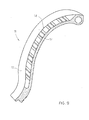
- Figure 5 shows very diagrammatically, in section, a resisting structure 11 - made according to the invention and usable to made a tensioning arm 5 and/or a guide 4 - which is U-shaped and comprises a pair of elongate outer branches 13 and spacer means 20, situated on the inside of said outer branches 13, suitable to carry the shoe 12 and to keep it at a preset distance from the bottom of the U-shaped resisting structure 11.
- spacer means 20 Some embodiments of the spacer means 20 will be described with reference to Figures 5-11.
- Figure 6 shows diagrammatically, in section, a resisting structure 11 according to the invention comprising a first embodiment of the spacer means 20 of Figure 5 which comprise, in section, a pair of elongate branches 14 - parallel to each other and to the outer branches 13 - which carry the shoe 12; without departing from the scope of the invention, the spacer means 20 can comprise only one elongate branch 14, parallel to the outer branches 13, which carries the shoe 12.
- the distance D between the branches 14 corresponds - more or less - to the width of the chain 1, whose side members 15 rest on the shoe 12 level the branches 14 of the resisting structure 11.
- the width of the branches 14 is preferably equal to that of the side members 15 of the chain 1 and in any case it is comprised between 1 and 3 times said width.
- the resisting structure 11 of Figure 6 does not have undercuts and therefore can be made by means of a relatively simple and inexpensive mould, which allows a good production rate to be achieved since at the same time it allows the production of a number of pieces larger than that which can be obtained according to the prior art.
- the branches 14 are advantageously smaller in height than the outer branches 13.
- the branches (14, 13) belonging to the resisting structure 11 are situated on the side of the resisting structure 11 to which is fixed the shoe 12 on which the chain 1 slides: the length of the outer branches 13 is therefore free from the limitations (presented by the resisting structures of the prior art) deriving from the presence of other mechanical members, belonging to the engine, situated in the immediate vicinity of the tensioning arm 5 and/or of the guide 4.
- the outer branches 13 can therefore be better sized to resist the bending stress to which the tensioning arm 5 and/or guide 4 are -subjected (or are expected to be subjected), increasing the reliability thereof.
- branches 14 can be connected to each other by a plurality of cross members designated by 17 in Figure 8 and/or each of the branches 14 can be connected to the outer adjacent branch 13 by a plurality of cross members designated by 16 in Figure 8.
- Figure 7 shows a side view of a tensioning arm comprising the resisting structure 11 of Figure 5; in Figure 7 one of the outer branches 13 can be seen.
- Figure 8 shows a front view of the resisting structure 11 of Figure 7; in Figure 8 the outer branches 13 and the branches 14 - which are connected to each other by a plurality of cross members 17 and to the adjacent outer branches 13 by a plurality of cross members 16 - can be seen.
- Figure 9 shows the resisting structure 11 of Figure 8, sectioned along the plane IX-IX of Figure 8; in Figure 9 there can be seen one of the branches 14, one of the outer branches 13 and a plurality of cross members 17, only one of which has been designated with the corresponding reference numeral for the sake of simplicity of the graphic representation.
- cross members 16 and 17 are inclined with respect to the branches 13 and 14 but, without departing from the scope of the invention, the cross members 16 and 17 can be perpendicular to the branches 13 and 14.
- Figures 10 and 11 show diagrammatically the top views of resisting structures 11 according to the invention comprising two further embodiments of the spacer means 20, which consist of at least one undulated support 21 ( Figure 10) on which rests the shoe 12 (omitted for the sake of simplicity of the graphic representation) or by a honeycomb structure 22 ( Figure 11) on which rests the shoe 12, omitted for the sake of simplicity of the graphic representation.
- the spacer means 20 consist of a plurality of protrusions 23 on which rests the shoe 12, omitted for the sake of simplicity of the graphic representation.
Landscapes
- Engineering & Computer Science (AREA)
- General Engineering & Computer Science (AREA)
- Mechanical Engineering (AREA)
- Devices For Conveying Motion By Means Of Endless Flexible Members (AREA)
Priority Applications (2)
| Application Number | Priority Date | Filing Date | Title |
|---|---|---|---|
| EP20030425348 EP1482209A1 (de) | 2003-05-30 | 2003-05-30 | Schiene zum Spannen und Führen einer Kette |
| JP2004127583A JP2004360897A (ja) | 2003-05-30 | 2004-04-23 | チェーン用テンショニング装置のテンショニング手段およびガイド手段のための耐力構造体 |
Applications Claiming Priority (1)
| Application Number | Priority Date | Filing Date | Title |
|---|---|---|---|
| EP20030425348 EP1482209A1 (de) | 2003-05-30 | 2003-05-30 | Schiene zum Spannen und Führen einer Kette |
Publications (1)
| Publication Number | Publication Date |
|---|---|
| EP1482209A1 true EP1482209A1 (de) | 2004-12-01 |
Family
ID=33104237
Family Applications (1)
| Application Number | Title | Priority Date | Filing Date |
|---|---|---|---|
| EP20030425348 Withdrawn EP1482209A1 (de) | 2003-05-30 | 2003-05-30 | Schiene zum Spannen und Führen einer Kette |
Country Status (2)
| Country | Link |
|---|---|
| EP (1) | EP1482209A1 (de) |
| JP (1) | JP2004360897A (de) |
Cited By (1)
| Publication number | Priority date | Publication date | Assignee | Title |
|---|---|---|---|---|
| CN103851145A (zh) * | 2012-11-29 | 2014-06-11 | 株式会社椿本链条 | 链条导件 |
Families Citing this family (1)
| Publication number | Priority date | Publication date | Assignee | Title |
|---|---|---|---|---|
| JP6108607B2 (ja) * | 2013-04-19 | 2017-04-05 | 株式会社椿本チエイン | チェーンガイド |
Citations (6)
| Publication number | Priority date | Publication date | Assignee | Title |
|---|---|---|---|---|
| DE3525746A1 (de) * | 1985-07-19 | 1987-01-22 | Klifa Gmbh & Co | Kettenspanner |
| DE19609583A1 (de) * | 1995-03-14 | 1996-09-19 | Borg Warner Automotive Kk | Spannarm und Kettenführung für einen hydraulischen Kettenspanner |
| DE19523912A1 (de) * | 1995-06-30 | 1997-03-27 | Bosch Gmbh Robert | Führungsschiene, insbesondere Spannschiene für einen Nockenwellenantrieb einer Brennkraftmaschine |
| DE19610301A1 (de) * | 1996-03-15 | 1997-09-18 | Audi Ag | Vorrichtung zum Spannen der Kette eines Kettentriebes |
| EP0856686A2 (de) * | 1997-02-01 | 1998-08-05 | Dr.Ing.h.c. F. Porsche Aktiengesellschaft | Gleitschiene zum Führen und/oder Spannen einer Kette |
| DE19721199C1 (de) * | 1997-05-21 | 1998-11-19 | Daimler Benz Ag | Spannschiene |
-
2003
- 2003-05-30 EP EP20030425348 patent/EP1482209A1/de not_active Withdrawn
-
2004
- 2004-04-23 JP JP2004127583A patent/JP2004360897A/ja active Pending
Patent Citations (6)
| Publication number | Priority date | Publication date | Assignee | Title |
|---|---|---|---|---|
| DE3525746A1 (de) * | 1985-07-19 | 1987-01-22 | Klifa Gmbh & Co | Kettenspanner |
| DE19609583A1 (de) * | 1995-03-14 | 1996-09-19 | Borg Warner Automotive Kk | Spannarm und Kettenführung für einen hydraulischen Kettenspanner |
| DE19523912A1 (de) * | 1995-06-30 | 1997-03-27 | Bosch Gmbh Robert | Führungsschiene, insbesondere Spannschiene für einen Nockenwellenantrieb einer Brennkraftmaschine |
| DE19610301A1 (de) * | 1996-03-15 | 1997-09-18 | Audi Ag | Vorrichtung zum Spannen der Kette eines Kettentriebes |
| EP0856686A2 (de) * | 1997-02-01 | 1998-08-05 | Dr.Ing.h.c. F. Porsche Aktiengesellschaft | Gleitschiene zum Führen und/oder Spannen einer Kette |
| DE19721199C1 (de) * | 1997-05-21 | 1998-11-19 | Daimler Benz Ag | Spannschiene |
Cited By (1)
| Publication number | Priority date | Publication date | Assignee | Title |
|---|---|---|---|---|
| CN103851145A (zh) * | 2012-11-29 | 2014-06-11 | 株式会社椿本链条 | 链条导件 |
Also Published As
| Publication number | Publication date |
|---|---|
| JP2004360897A (ja) | 2004-12-24 |
Similar Documents
| Publication | Publication Date | Title |
|---|---|---|
| EP0890042B1 (de) | Kettenspanner mit dämpfungsmechanismus | |
| EP2496861B1 (de) | Mehrsträngige spannungsanordnung mit beweglichen armen | |
| US6322470B1 (en) | Pivoting dual arm chain tensioner system for contacting multiple chain strands | |
| KR101803255B1 (ko) | 일방향 댐핑 기구를 구비한 기계식 인장기 | |
| KR101318131B1 (ko) | 체인 구동의 두 스트랜드들을 연결하는 체인 텐셔닝 장치 | |
| US20090036243A1 (en) | Blade tensioner with opposing spans | |
| BR0208779A (pt) | Sistema de acionamento por correia do tensionador de amortecimento assimétrico | |
| RU2003112688A (ru) | Система привода вспомогательных механизмов, включающая в себя мотор/генератор | |
| US8348792B2 (en) | Traction mechanism drive | |
| EP1482209A1 (de) | Schiene zum Spannen und Führen einer Kette | |
| JP2009505021A (ja) | チェーンスパン横断減衰機構を備えた機械式枢支テンショナ | |
| EP1182378A2 (de) | Ketten- oder Riemenspannarm | |
| CN105593568B (zh) | 包括油湿齿形带的传动系统 | |
| US5125281A (en) | Drive unit incorporated linear motion guide assembly | |
| KR100922462B1 (ko) | 동력 전달 구동부 및 동력 전달 구동부 내에 일체되기 위한 인장 또는 안내 요소 | |
| US20090156339A1 (en) | Chain guide for transmission device | |
| EP2123937A3 (de) | Gelenkkettenantrieb | |
| JP2000314324A (ja) | 予荷重力を循環駆動要素に付与する方法 | |
| ATE352484T1 (de) | Trimmvorrichtung für schiffe kleiner tonnage | |
| KR100357544B1 (ko) | 자동차용 타이밍 벨트 텐셔너 장치 | |
| JP2002039298A (ja) | 駆動伝達装置における張力調整装置 | |
| EP1496290B1 (de) | Kettenspanner für eine Verteilerkette | |
| KR101028453B1 (ko) | 체인 구동 시스템의 체인 소음 저감 구조 | |
| JP2007032838A (ja) | テンショニングシステム | |
| JP4777660B2 (ja) | ブレードテンショナ装置 |
Legal Events
| Date | Code | Title | Description |
|---|---|---|---|
| PUAI | Public reference made under article 153(3) epc to a published international application that has entered the european phase |
Free format text: ORIGINAL CODE: 0009012 |
|
| AK | Designated contracting states |
Kind code of ref document: A1 Designated state(s): AT BE BG CH CY CZ DE DK EE ES FI FR GB GR HU IE IT LI LU MC NL PT RO SE SI SK TR |
|
| AX | Request for extension of the european patent |
Extension state: AL LT LV MK |
|
| 17P | Request for examination filed |
Effective date: 20050201 |
|
| 17Q | First examination report despatched |
Effective date: 20050330 |
|
| AKX | Designation fees paid |
Designated state(s): DE FR IT |
|
| STAA | Information on the status of an ep patent application or granted ep patent |
Free format text: STATUS: THE APPLICATION IS DEEMED TO BE WITHDRAWN |
|
| 18D | Application deemed to be withdrawn |
Effective date: 20090630 |