EP1482252A2 - Klimaanlage - Google Patents
Klimaanlage Download PDFInfo
- Publication number
- EP1482252A2 EP1482252A2 EP04005379A EP04005379A EP1482252A2 EP 1482252 A2 EP1482252 A2 EP 1482252A2 EP 04005379 A EP04005379 A EP 04005379A EP 04005379 A EP04005379 A EP 04005379A EP 1482252 A2 EP1482252 A2 EP 1482252A2
- Authority
- EP
- European Patent Office
- Prior art keywords
- air
- room
- ventilating system
- ceiling surface
- outdoor
- Prior art date
- Legal status (The legal status is an assumption and is not a legal conclusion. Google has not performed a legal analysis and makes no representation as to the accuracy of the status listed.)
- Withdrawn
Links
- 238000004378 air conditioning Methods 0.000 title claims abstract description 35
- 230000001172 regenerating effect Effects 0.000 claims abstract description 15
- 238000007599 discharging Methods 0.000 claims abstract description 6
- 230000001154 acute effect Effects 0.000 claims description 2
- 230000008859 change Effects 0.000 claims description 2
- 238000009423 ventilation Methods 0.000 description 10
- 238000010586 diagram Methods 0.000 description 7
- 238000001816 cooling Methods 0.000 description 6
- 238000010438 heat treatment Methods 0.000 description 6
- 239000003507 refrigerant Substances 0.000 description 6
- 238000004140 cleaning Methods 0.000 description 3
- CURLTUGMZLYLDI-UHFFFAOYSA-N Carbon dioxide Chemical compound O=C=O CURLTUGMZLYLDI-UHFFFAOYSA-N 0.000 description 2
- 230000003749 cleanliness Effects 0.000 description 2
- 230000002708 enhancing effect Effects 0.000 description 2
- 239000000463 material Substances 0.000 description 2
- 230000004048 modification Effects 0.000 description 2
- 238000012986 modification Methods 0.000 description 2
- XAGFODPZIPBFFR-UHFFFAOYSA-N aluminium Chemical compound [Al] XAGFODPZIPBFFR-UHFFFAOYSA-N 0.000 description 1
- 229910052782 aluminium Inorganic materials 0.000 description 1
- QVGXLLKOCUKJST-UHFFFAOYSA-N atomic oxygen Chemical compound [O] QVGXLLKOCUKJST-UHFFFAOYSA-N 0.000 description 1
- 238000007664 blowing Methods 0.000 description 1
- 229910002092 carbon dioxide Inorganic materials 0.000 description 1
- 239000001569 carbon dioxide Substances 0.000 description 1
- 238000000034 method Methods 0.000 description 1
- 229910052760 oxygen Inorganic materials 0.000 description 1
- 239000001301 oxygen Substances 0.000 description 1
- 230000008569 process Effects 0.000 description 1
- 230000003252 repetitive effect Effects 0.000 description 1
- 238000009827 uniform distribution Methods 0.000 description 1
- 239000002699 waste material Substances 0.000 description 1
Images




Classifications
-
- F—MECHANICAL ENGINEERING; LIGHTING; HEATING; WEAPONS; BLASTING
- F24—HEATING; RANGES; VENTILATING
- F24F—AIR-CONDITIONING; AIR-HUMIDIFICATION; VENTILATION; USE OF AIR CURRENTS FOR SCREENING
- F24F3/00—Air-conditioning systems in which conditioned primary air is supplied from one or more central stations to distributing units in the rooms or spaces where it may receive secondary treatment; Apparatus specially designed for such systems
- F24F3/12—Air-conditioning systems in which conditioned primary air is supplied from one or more central stations to distributing units in the rooms or spaces where it may receive secondary treatment; Apparatus specially designed for such systems characterised by the treatment of the air otherwise than by heating and cooling
- F24F3/14—Air-conditioning systems in which conditioned primary air is supplied from one or more central stations to distributing units in the rooms or spaces where it may receive secondary treatment; Apparatus specially designed for such systems characterised by the treatment of the air otherwise than by heating and cooling by humidification; by dehumidification
- F24F3/147—Air-conditioning systems in which conditioned primary air is supplied from one or more central stations to distributing units in the rooms or spaces where it may receive secondary treatment; Apparatus specially designed for such systems characterised by the treatment of the air otherwise than by heating and cooling by humidification; by dehumidification with both heat and humidity transfer between supplied and exhausted air
-
- F—MECHANICAL ENGINEERING; LIGHTING; HEATING; WEAPONS; BLASTING
- F24—HEATING; RANGES; VENTILATING
- F24F—AIR-CONDITIONING; AIR-HUMIDIFICATION; VENTILATION; USE OF AIR CURRENTS FOR SCREENING
- F24F1/00—Room units for air-conditioning, e.g. separate or self-contained units or units receiving primary air from a central station
- F24F1/0007—Indoor units, e.g. fan coil units
- F24F1/0011—Indoor units, e.g. fan coil units characterised by air outlets
-
- F—MECHANICAL ENGINEERING; LIGHTING; HEATING; WEAPONS; BLASTING
- F24—HEATING; RANGES; VENTILATING
- F24F—AIR-CONDITIONING; AIR-HUMIDIFICATION; VENTILATION; USE OF AIR CURRENTS FOR SCREENING
- F24F1/00—Room units for air-conditioning, e.g. separate or self-contained units or units receiving primary air from a central station
- F24F1/0007—Indoor units, e.g. fan coil units
- F24F1/0035—Indoor units, e.g. fan coil units characterised by introduction of outside air to the room
-
- F—MECHANICAL ENGINEERING; LIGHTING; HEATING; WEAPONS; BLASTING
- F24—HEATING; RANGES; VENTILATING
- F24F—AIR-CONDITIONING; AIR-HUMIDIFICATION; VENTILATION; USE OF AIR CURRENTS FOR SCREENING
- F24F1/00—Room units for air-conditioning, e.g. separate or self-contained units or units receiving primary air from a central station
- F24F1/0007—Indoor units, e.g. fan coil units
- F24F1/0035—Indoor units, e.g. fan coil units characterised by introduction of outside air to the room
- F24F1/0038—Indoor units, e.g. fan coil units characterised by introduction of outside air to the room in combination with simultaneous exhaustion of inside air
-
- F—MECHANICAL ENGINEERING; LIGHTING; HEATING; WEAPONS; BLASTING
- F24—HEATING; RANGES; VENTILATING
- F24F—AIR-CONDITIONING; AIR-HUMIDIFICATION; VENTILATION; USE OF AIR CURRENTS FOR SCREENING
- F24F1/00—Room units for air-conditioning, e.g. separate or self-contained units or units receiving primary air from a central station
- F24F1/0007—Indoor units, e.g. fan coil units
- F24F1/0043—Indoor units, e.g. fan coil units characterised by mounting arrangements
- F24F1/0047—Indoor units, e.g. fan coil units characterised by mounting arrangements mounted in the ceiling or at the ceiling
-
- F—MECHANICAL ENGINEERING; LIGHTING; HEATING; WEAPONS; BLASTING
- F24—HEATING; RANGES; VENTILATING
- F24F—AIR-CONDITIONING; AIR-HUMIDIFICATION; VENTILATION; USE OF AIR CURRENTS FOR SCREENING
- F24F1/00—Room units for air-conditioning, e.g. separate or self-contained units or units receiving primary air from a central station
- F24F1/0007—Indoor units, e.g. fan coil units
- F24F1/0059—Indoor units, e.g. fan coil units characterised by heat exchangers
- F24F1/0063—Indoor units, e.g. fan coil units characterised by heat exchangers by the mounting or arrangement of the heat exchangers
-
- F—MECHANICAL ENGINEERING; LIGHTING; HEATING; WEAPONS; BLASTING
- F24—HEATING; RANGES; VENTILATING
- F24F—AIR-CONDITIONING; AIR-HUMIDIFICATION; VENTILATION; USE OF AIR CURRENTS FOR SCREENING
- F24F1/00—Room units for air-conditioning, e.g. separate or self-contained units or units receiving primary air from a central station
- F24F1/0007—Indoor units, e.g. fan coil units
- F24F1/0059—Indoor units, e.g. fan coil units characterised by heat exchangers
- F24F1/0067—Indoor units, e.g. fan coil units characterised by heat exchangers by the shape of the heat exchangers or of parts thereof, e.g. of their fins
-
- F—MECHANICAL ENGINEERING; LIGHTING; HEATING; WEAPONS; BLASTING
- F24—HEATING; RANGES; VENTILATING
- F24F—AIR-CONDITIONING; AIR-HUMIDIFICATION; VENTILATION; USE OF AIR CURRENTS FOR SCREENING
- F24F1/00—Room units for air-conditioning, e.g. separate or self-contained units or units receiving primary air from a central station
- F24F1/0007—Indoor units, e.g. fan coil units
- F24F1/0071—Indoor units, e.g. fan coil units with means for purifying supplied air
- F24F1/0073—Indoor units, e.g. fan coil units with means for purifying supplied air characterised by the mounting or arrangement of filters
-
- F—MECHANICAL ENGINEERING; LIGHTING; HEATING; WEAPONS; BLASTING
- F24—HEATING; RANGES; VENTILATING
- F24F—AIR-CONDITIONING; AIR-HUMIDIFICATION; VENTILATION; USE OF AIR CURRENTS FOR SCREENING
- F24F12/00—Use of energy recovery systems in air conditioning, ventilation or screening
- F24F12/001—Use of energy recovery systems in air conditioning, ventilation or screening with heat-exchange between supplied and exhausted air
- F24F12/006—Use of energy recovery systems in air conditioning, ventilation or screening with heat-exchange between supplied and exhausted air using an air-to-air heat exchanger
-
- F—MECHANICAL ENGINEERING; LIGHTING; HEATING; WEAPONS; BLASTING
- F24—HEATING; RANGES; VENTILATING
- F24F—AIR-CONDITIONING; AIR-HUMIDIFICATION; VENTILATION; USE OF AIR CURRENTS FOR SCREENING
- F24F13/00—Details common to, or for air-conditioning, air-humidification, ventilation or use of air currents for screening
- F24F13/02—Ducting arrangements
- F24F13/06—Outlets for directing or distributing air into rooms or spaces, e.g. ceiling air diffuser
-
- F—MECHANICAL ENGINEERING; LIGHTING; HEATING; WEAPONS; BLASTING
- F24—HEATING; RANGES; VENTILATING
- F24F—AIR-CONDITIONING; AIR-HUMIDIFICATION; VENTILATION; USE OF AIR CURRENTS FOR SCREENING
- F24F1/00—Room units for air-conditioning, e.g. separate or self-contained units or units receiving primary air from a central station
- F24F1/0007—Indoor units, e.g. fan coil units
- F24F1/0018—Indoor units, e.g. fan coil units characterised by fans
- F24F1/0022—Centrifugal or radial fans
-
- F—MECHANICAL ENGINEERING; LIGHTING; HEATING; WEAPONS; BLASTING
- F24—HEATING; RANGES; VENTILATING
- F24F—AIR-CONDITIONING; AIR-HUMIDIFICATION; VENTILATION; USE OF AIR CURRENTS FOR SCREENING
- F24F13/00—Details common to, or for air-conditioning, air-humidification, ventilation or use of air currents for screening
- F24F13/02—Ducting arrangements
- F24F13/06—Outlets for directing or distributing air into rooms or spaces, e.g. ceiling air diffuser
- F24F2013/0616—Outlets that have intake openings
-
- Y—GENERAL TAGGING OF NEW TECHNOLOGICAL DEVELOPMENTS; GENERAL TAGGING OF CROSS-SECTIONAL TECHNOLOGIES SPANNING OVER SEVERAL SECTIONS OF THE IPC; TECHNICAL SUBJECTS COVERED BY FORMER USPC CROSS-REFERENCE ART COLLECTIONS [XRACs] AND DIGESTS
- Y02—TECHNOLOGIES OR APPLICATIONS FOR MITIGATION OR ADAPTATION AGAINST CLIMATE CHANGE
- Y02B—CLIMATE CHANGE MITIGATION TECHNOLOGIES RELATED TO BUILDINGS, e.g. HOUSING, HOUSE APPLIANCES OR RELATED END-USER APPLICATIONS
- Y02B30/00—Energy efficient heating, ventilation or air conditioning [HVAC]
- Y02B30/56—Heat recovery units
Definitions
- the present invention relates to air conditioning systems, and more particularly, to an air conditioning and ventilating system which enables ventilation during operation of an air conditioner.
- the air conditioner conditions a temperature, a humidity, air motion, and cleanliness of air in a particular area to suit to a purpose of use.
- the air conditioner is provided with a compressor and a heat exchanger to circulate refrigerant for cooling or heating a room space, such as a residential space, a restaurant, a library, or an office.
- the related art air conditioner is provided with a compressor for compressing refrigerant to high temperature and pressure, an outdoor heat exchanger for making the refrigerant in the air conditioner to heat exchange with room air, and an expansion device between an indoor heat exchanger and the outdoor heat exchanger.
- the outdoor heat exchanger serves as a condenser or an evaporator depending on an operation condition
- the indoor heat exchanger serves as an evaporator or a condenser, opposite to the outdoor heat exchanger.
- the indoor heat exchanger serves as the evaporator
- the room is cooled
- the indoor heat exchanger serves as the condenser
- the room is closed during operation of the air conditioner. If the air conditioner is operated in a state the room is closed, a carbon dioxide content of the room increases as time passes by, to contaminate the room air. Therefore, it is required to ventilate the room at regular intervals for making the more comfortable, when a ventilating device is in general used.
- the room air has been forcibly discharged to an outside of the room with a fan.
- the forced discharge of room air to an outside of the room with one fan causes problems in that it is liable to cause shortage of oxygen in the room as fresh air is not introduced into the room properly, and there is a waste of energy as cooled down, or heated room air is discharged to the outside of the room as it is, and an outdoor air having great temperature or humidity difference from the room air is introduced into the room though gaps of doors and windows.
- the present invention is directed to an air conditioning and ventilating system that substantially obviates one or more of the problems due to limitations and disadvantages of the related art.
- An object of the present invention is to provide an air conditioning system, in which can carry of ventilation exclusively, or together with cooling or heating.
- Another object of the present invention is to provide an air conditioning and ventilating system which can minimize heat loss even during ventilation.
- Another object of the present invention is to provide an air conditioning and ventilating system which can make a uniform distribution of air introduced into a room from an outdoor to supply enough fresh air to persons in the room.
- the air conditioning and ventilating system includes an air conditioner installed on a ceiling, having air outlets for discharging air having heat heat exchanged at an indoor heat exchanger, and a device for controlling a direction of air discharged from the air outlets, a first air passage for guiding outdoor air to a room, and a second air passage for guiding room air to an outdoor.
- the first air passage, and the second air passage are closable.
- the device includes a deflecting plate.
- the deflecting plate is tilted at an angle from a ceiling surface for directing the air from the air outlet, not vertical to the ceiling surface, but at an angle from the ceiling surface.
- the deflecting plate is arranged along a side of the air outlet, tilted toward the ceiling surface having the air outlet formed therein.
- the deflecting plate is tilted at an angle in a range of 15° ⁇ 45° from the ceiling surface having the air outlet formed therein, in a case a temperature of the air discharged to the room through the first air passage is higher than a temperature of the room air.
- the deflecting plate is tilted at an angle in a range of 45° ⁇ 90° from the ceiling surface having the air outlet formed therein, in a case a temperature of the air discharged to the room through the first air passage is lower than a temperature of the room air.
- the device further includes a controlling part for controlling an angle of the deflecting plate.
- the deflecting plate swings automatically within a preset range of angle from the ceiling surface having the air outlet formed therein, for automatic change of a direction of the air discharged to the room through the air outlet.
- the first air passage includes at least one air inlet port for supplying air to the room in a direction the ceiling surface forms an acute angle from the deflecting plate.
- the first, and second air passages cross at a part.
- the air conditioning and ventilating further includes a regenerative heat exchanger at the cross part of the first air passage, and the second air passage for making the room air and the outdoor air passed through the cross part to heat exchange with each other.
- the air conditioning and ventilating system enables ventilation even during cooling/heating operation, minimizes a heat loss during the ventilation, and supplies outdoor fresh air to entire room, uniformly.
- the air conditioner conditions a temperature, a humidity, air motion, and cleanliness of air in a particular area to suit to a purpose of use.
- the air conditioner cools or heats a room space, such as a residential space, a restaurant, a library, or an office.
- the air conditioner has an indoor unit and an outdoor unit.
- the indoor unit is installed in a room, and has an indoor heat exchanger.
- the outdoor unit is installed in an outdoor, and has an outdoor heat exchanger for heat exchanging with an outdoor air.
- the air conditioner also has a compressor for compressing refrigerant to high temperature and pressure, and an expansion device between an indoor heat exchanger and the outdoor heat exchanger, for expanding the high pressure, high temperature refrigerant to a low temperature, low pressure refrigerant.
- the air conditioning and ventilating system includes an air conditioner for cooling/heating a room, a first air passage 10 for guiding air from an outdoor to an indoor, and a second air passage 20 for guiding air from the indoor to the outdoor.
- the air conditioner includes an indoor unit 50, and an outdoor unit (not shown) having an outdoor heat exchanger.
- the indoor unit 50 includes an indoor heat exchanger for serving as an evaporator or a condenser depending on an operation condition, and a fan for drawing room air, and blowing the room air having heat exchanged at the indoor heat exchanger to the room again.
- the fan is a centrifugal fan 52 in a central part of the indoor unit, and the indoor heat exchanger 51 is arranged in a direction the air is discharged from the centrifugal fan.
- indoor unit is installed in a central part of ceiling, the position may vary with a room structure, and a number of the indoor units may also vary with a room space.
- the fan in the indoor unit may be an axial fan, when the indoor heat exchanger is installed on a discharge side of the axial fan.
- the first air passage 10 and the second air passage 20 are closable, and parts of which intersect at a position where the regenerative heat exchanger 30 is preferably provided.
- the outdoor air supplied to the room through the first air passage and the room air discharged to the outdoor through the second air passage 20 make heat exchange at the regenerative heat exchanger 30.
- the regenerative heat exchanger 30 is provided thus for recovering a portion of energy to reduce an energy loss.
- the regenerative heat exchanger 30 includes a first flow part 31 having a plurality of flow passages for passing air introduced from the outdoor and flowing through the first air passage 10, and a second flow part 32 having a plurality of flow passages in contact with the first flow part for passing air from the room and flowing through the second air passage 20.
- interfaces of the first flow part 31 and the second flow part 32 are made of heat exchange films of a material having an excellent heat conductivity.
- An embodiment of the regenerative heat exchanger will be described with reference to FIG. 3B.
- the regenerative heat exchanger may include a plurality of layers having an alternative stack of the first flow part 310 and the second flow part 320, for increasing a heat exchange area to enhance a heat exchange efficiency. It is preferable that walls of the first flow part 310 and the second flow part 320 are formed of a material having an excellent heat conductivity, such as aluminum.
- the second flow part may include a plurality of pipes passing through the first flow part. That is, any structure that can maximize a heat exchange area of the first flow part and the second flow part can be employed.
- the first air passage 10 includes a first fan 15 for drawing outdoor air forcibly and discharging to the room.
- the first fan can be arranged on any point of the first air passage 10, in the embodiment of the present invention, the first fan is arranged on an air discharge side of the first flow part 31.
- the first air passage 10 may further include an air cleaning filter 16 for removing foreign matters from the air introduced from the outdoor.
- the air cleaning filter 16 can be installed on any point of the first air passage 10, the air cleaning filter 16 is arranged on an air inlet side of the first flow part in the embodiment.
- the second air passage 20 includes a second fan 25 for drawing room air forcibly, and discharging toward the outdoor.
- the second fan 25 can be arranged on any point of the second air passage 20, in the embodiment, the second fan 25 is arranged on an air outlet side of the second flow part 32.
- Each of the air inlet ports 11 is connected to a room side end of the first air passage 10, to form a part of the first air passage 10, and each of the air outlet ports 21 is connected a room side end of the second air passage 20, to form a part of the second air passage 20.
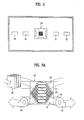
- FIG. 2 illustrates a diagram of a ceiling of a room having an air conditioning and ventilating system shown in FIG. 1 installed thereon.
- the indoor unit further includes a square panel 53 under the centrifugal fan and the indoor heat exchanger.
- the panel 53 includes an air inlet 54 for passing room air from the room toward the centrifugal fan 52, and air outlets 55 around the air inlet 54 for supplying the room air having heat exchanged at the indoor heat exchanger to the room.
- the indoor unit further includes deflecting devices for deflecting a direction of air supplied to the room through the air outlets. Because the outdoor air, supplied to the room through the first air passage 10, has a temperature and a humidity, and the like different from the room air, that may impede smooth circulation of the air. This is because there are slight differences between the outdoor air and the room air even if the regenerative heat exchanger 30 is provided.
- the outdoor air supplied to the room has a temperature higher than air temperature of the room. Due to this, there is a density difference between the room air and the outdoor air, such that the outdoor air with a low density does not fall down, but stays near to the ceiling, failing in uniform supply of fresh air to the entire room.
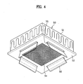
- the deflecting device for making smooth room air circulation for making the fresh air and the air discharged from the indoor unit to reach every place of the room, the deflecting device includes a deflecting plate 56 attached to the air outlet side.
- the deflecting plate 56 is attached such that the air discharged to the room through the air outlet 55 is directed, not vertical to a ceiling surface, but at an angle from the ceiling surface.
- the deflecting plate 56 is attached to part along one side of the rectangular air outlet 55, tilted toward a direction of the ceiling surface the air outlet is formed therein.
- the direction of the ceiling surface the air outlet is formed therein toward which the defecting plate 56 is tilted is the same with a direction in which the air inlet ports 11 of the first air passage 10 are formed therein.
- FIGS. 5 and 6 illustrate operation states of an air conditioning and ventilating system for different indoor and outdoor environments.
- the deflecting plate 56 is tilted at an angle in a range of 15° ⁇ 45° from the ceiling surface having the air outlets formed therein, for circulation of the fresh air staying close to the ceiling to entire room by the air from the air outlets.
- the deflecting plate 56 is tilted at an angle in a range of 45° ⁇ 90° from the ceiling surface having the air outlets formed therein.
- the defecting device may further include a controlling part (not shown) for controlling an angle of the defecting plate according to an air conditioning environment.
- the deflecting plate 56 may be controlled by the controlling part such that a direction of air discharged from the air outlet into the room is varied automatically. In other words, the deflecting plate may swing automatically within a preset range.
- FIG. 4 illustrates a hexahedral indoor unit
- the shape is not limited to this.
- the air outlets may be circular surrounding the air inlet, when the deflecting plates may be projected toward room from an inner side of the air outlets. That is, the deflecting plates may be applied in various forms according to positions and forms of the air outlets, and air inlet.
- both the first air passage 10 and the second air passage 20 are opened, and the fans 15, and 25 on respective air passages are put into operation.
- the outdoor air is introduced into the first flow part 31 of the regenerative heat exchanger 30 through the first air passage 10, and the room air is introduced into the second flow part 32 through the second air passage 20, to make heat exchange with each other.
- the outdoor air having a regenerative heat exchanger process passed through thus is supplied to room through the air inlet in the ceiling.
- the air conditioner is operated in a cooling mode, the temperature of the outdoor air is higher than the temperature of room air, such that the outdoor air fails to circulate through entire room, but stays close to the ceiling.
- the defecting plate is tilted at an angle in a range of 14° ⁇ 45° from the ceiling surface by the controlling part, to enable the outdoor air staying close to the ceiling surface to circulate through the entire room.
- the deflecting plate is tilted at an angle in a range of 45° ⁇ 90° from the ceiling surface by the controlling part.
- the air conditioning and ventilating system of the present invention has the following advantages.
- the heat exchange between the outdoor air introduced into the room through the first air passage 10 and the room air discharged to the outdoor at the regenerative heat exchanger 30 permits to reduce a heat loss.
- the quick supply of fresh air to entire room can save power consumption because a ventilation time period is required no more than necessary.
Landscapes
- Engineering & Computer Science (AREA)
- Chemical & Material Sciences (AREA)
- Combustion & Propulsion (AREA)
- Mechanical Engineering (AREA)
- General Engineering & Computer Science (AREA)
- Physics & Mathematics (AREA)
- Thermal Sciences (AREA)
- Air Conditioning Control Device (AREA)
- Air-Flow Control Members (AREA)
- Central Air Conditioning (AREA)
Applications Claiming Priority (2)
| Application Number | Priority Date | Filing Date | Title |
|---|---|---|---|
| KR2003034079 | 2003-05-28 | ||
| KR1020030034079A KR100628205B1 (ko) | 2003-05-28 | 2003-05-28 | 환기겸용 공조시스템 및 그 제어방법 |
Publications (2)
| Publication Number | Publication Date |
|---|---|
| EP1482252A2 true EP1482252A2 (de) | 2004-12-01 |
| EP1482252A3 EP1482252A3 (de) | 2006-05-17 |
Family
ID=33129044
Family Applications (1)
| Application Number | Title | Priority Date | Filing Date |
|---|---|---|---|
| EP04005379A Withdrawn EP1482252A3 (de) | 2003-05-28 | 2004-03-06 | Klimaanlage |
Country Status (5)
| Country | Link |
|---|---|
| US (1) | US7185510B2 (de) |
| EP (1) | EP1482252A3 (de) |
| JP (1) | JP2004354040A (de) |
| KR (1) | KR100628205B1 (de) |
| CN (1) | CN1277077C (de) |
Cited By (8)
| Publication number | Priority date | Publication date | Assignee | Title |
|---|---|---|---|---|
| EP2017542A4 (de) * | 2006-04-21 | 2011-12-07 | Daikin Ind Ltd | Klimaanlage |
| EP2405211A1 (de) * | 2010-07-08 | 2012-01-11 | FCR S.p.A. | Luftverteiler für Klimaanlage |
| EP2530397A1 (de) * | 2011-05-30 | 2012-12-05 | Koolair, S.A. | Luftdiffusor |
| EP2899472A1 (de) * | 2014-01-27 | 2015-07-29 | Lg Electronics Inc. | Innenraumeinheit für Klimaanlage mit Windschützen |
| US9174378B2 (en) | 2010-08-16 | 2015-11-03 | Nylstar, S.A. | Cosmetic textile fiber, method for obtaining it and use thereof |
| US10047972B2 (en) | 2013-10-02 | 2018-08-14 | Lg Electronics Inc. | Indoor device for cassette type air conditioner |
| US10197298B2 (en) | 2013-10-02 | 2019-02-05 | Lg Electronics Inc. | Indoor device for cassette type air conditioner |
| US10203150B2 (en) | 2013-10-11 | 2019-02-12 | Lg Electronics Inc. | Indoor device for air conditioner |
Families Citing this family (31)
| Publication number | Priority date | Publication date | Assignee | Title |
|---|---|---|---|---|
| KR100628078B1 (ko) * | 2005-02-15 | 2006-09-26 | 엘지전자 주식회사 | 환기시스템 |
| KR100791926B1 (ko) * | 2006-11-13 | 2008-01-04 | 삼성전자주식회사 | 공기조화기의 운전제어방법 |
| FI122295B (fi) * | 2007-02-16 | 2011-11-15 | Halton Oy | Tuloilmalaite |
| JP5061642B2 (ja) * | 2007-02-23 | 2012-10-31 | ダイキン工業株式会社 | 空調換気装置 |
| US20080311841A1 (en) * | 2007-06-13 | 2008-12-18 | Daud Taslim | External Wind Reflector |
| US20090156115A1 (en) * | 2007-12-13 | 2009-06-18 | Rr Advanced Energy Systems Ltd. | Method And System For Ventilating A Space |
| JP4483990B2 (ja) * | 2008-11-20 | 2010-06-16 | ダイキン工業株式会社 | 空気調和機 |
| KR101558572B1 (ko) * | 2008-12-23 | 2015-10-07 | 엘지전자 주식회사 | 공기조화기 제어방법 |
| FR2947040B1 (fr) * | 2009-06-23 | 2014-01-03 | Cinier Radiateurs | Radiateur reversible |
| JP5427833B2 (ja) * | 2011-05-18 | 2014-02-26 | パナソニック株式会社 | クリーンルームの逆流防止装置 |
| CN103161328B (zh) * | 2011-12-12 | 2015-03-11 | 深圳市华为安捷信电气有限公司 | 通讯机房及其风道调节方法 |
| CN103512142A (zh) * | 2012-06-27 | 2014-01-15 | 刘华荣 | 联动空调的多功能高节能新风系统 |
| ES2764398T3 (es) * | 2013-01-21 | 2020-06-03 | Carrier Corp | Terminal de aire avanzado |
| KR102053223B1 (ko) * | 2013-07-02 | 2020-01-07 | 엘지전자 주식회사 | 바람 가리개 및 이를 포함한 공기 조화기 |
| US10473348B2 (en) * | 2014-11-10 | 2019-11-12 | Internal Air Flow Dynamics, Llc | Method and system for eliminating air stratification via ductless devices |
| DE102014016878A1 (de) * | 2014-11-14 | 2016-05-19 | Andreas Weichselgartner | Klimaanlage mit Windschild |
| CN105546709B (zh) * | 2016-02-04 | 2019-01-04 | 山东格瑞德集团有限公司 | 孔板送风布风系统 |
| CN105650772A (zh) * | 2016-03-18 | 2016-06-08 | 轨道交通节能北京市工程研究中心有限公司 | 地铁车站双旋动蒸发冷凝型冷媒直接膨胀式通风空调系统 |
| CN105627491A (zh) * | 2016-03-18 | 2016-06-01 | 轨道交通节能北京市工程研究中心有限公司 | 地铁车站采用的双旋动蒸发冷凝型冷水式通风空调系统 |
| CN106871396A (zh) * | 2017-04-20 | 2017-06-20 | 林永冠 | 热能回收设备及热水冷暖气一体机 |
| CN108592186A (zh) * | 2018-04-12 | 2018-09-28 | 中国建筑股份有限公司 | 大空间的微环境品质控制系统 |
| CN108662715A (zh) * | 2018-05-21 | 2018-10-16 | 珠海格力电器股份有限公司 | 新风系统、空调器和空调器的控制方法 |
| CN110356309A (zh) * | 2019-08-07 | 2019-10-22 | 河海大学常州校区 | 一种休息仓 |
| US11511013B2 (en) | 2020-05-08 | 2022-11-29 | Madhavan Pisharodi | Air purification and disinfection apparatus and methods of use |
| WO2021225614A1 (en) * | 2020-05-08 | 2021-11-11 | Madhavan Pisharodi | Systems, apparatus and methods for purifying air |
| US12194206B2 (en) | 2021-08-16 | 2025-01-14 | Perumala Holdings, LLC | Expandable system for purification and disinfection of air |
| US12564627B2 (en) | 2021-08-16 | 2026-03-03 | Perumala Holdings, LLC | System for producing and delivering contactless veterinary passive immunization |
| US12298037B2 (en) | 2021-08-16 | 2025-05-13 | Perumala Holdings, LLC | System for delivery of inactivated pathogens for contactless passive immunization |
| US11951164B2 (en) | 2021-08-16 | 2024-04-09 | Perumala Holdings, LLC | Systems and methods for the preparation of vaccines utilizing predictably inactivated pathogens |
| US12465537B2 (en) | 2023-06-02 | 2025-11-11 | Perumala Holdings, LLC | Self-cleaning air flow for air-conditioned facilities |
| CN117213003A (zh) * | 2023-09-21 | 2023-12-12 | 深圳供电局有限公司 | 空调自动调节方法、装置、计算机设备和存储介质 |
Family Cites Families (11)
| Publication number | Priority date | Publication date | Assignee | Title |
|---|---|---|---|---|
| JPS5163261U (de) * | 1974-11-13 | 1976-05-18 | ||
| JPS6078242A (ja) * | 1983-10-03 | 1985-05-02 | Hitachi Ltd | 天井埋込形空気調和機 |
| JP3240854B2 (ja) * | 1994-09-26 | 2001-12-25 | 三菱電機株式会社 | 空気調和機の吹出口 |
| JP2993412B2 (ja) * | 1995-11-20 | 1999-12-20 | 三菱電機株式会社 | 吹出口及び該吹出口を備えた空気調和装置 |
| FR2778228B1 (fr) * | 1998-05-04 | 2000-10-06 | Robert Ribo | Procede et dispositif de climatisation et/ou de chauffage d'un local comprenant au moins une piece de service et au moins deux pieces principales |
| JP3285023B2 (ja) | 1999-11-05 | 2002-05-27 | ダイキン工業株式会社 | 天井埋込型空気調和装置 |
| JP2001227772A (ja) * | 1999-12-03 | 2001-08-24 | Mitsubishi Heavy Ind Ltd | 埋込型空気調和機及び空気調和システム |
| US6213867B1 (en) * | 2000-01-12 | 2001-04-10 | Air Handling Engineering Ltd. | Venturi type air distribution system |
| US6386970B1 (en) * | 2000-04-17 | 2002-05-14 | Vernier, Ii Larry D. | Air diffuser |
| CN1139762C (zh) | 2001-12-12 | 2004-02-25 | 邓金荣 | 全新风节能空调器 |
| KR100411791B1 (ko) | 2001-12-14 | 2003-12-24 | 삼성전자주식회사 | 천장매입형 공기조화기 |
-
2003
- 2003-05-28 KR KR1020030034079A patent/KR100628205B1/ko not_active Expired - Fee Related
-
2004
- 2004-03-06 EP EP04005379A patent/EP1482252A3/de not_active Withdrawn
- 2004-03-15 JP JP2004073201A patent/JP2004354040A/ja active Pending
- 2004-03-18 CN CNB2004100300568A patent/CN1277077C/zh not_active Expired - Fee Related
- 2004-03-25 US US10/808,450 patent/US7185510B2/en not_active Expired - Fee Related
Cited By (10)
| Publication number | Priority date | Publication date | Assignee | Title |
|---|---|---|---|---|
| EP2017542A4 (de) * | 2006-04-21 | 2011-12-07 | Daikin Ind Ltd | Klimaanlage |
| US8511108B2 (en) | 2006-04-21 | 2013-08-20 | Daikin Industries, Ltd. | Air conditioning unit |
| EP2405211A1 (de) * | 2010-07-08 | 2012-01-11 | FCR S.p.A. | Luftverteiler für Klimaanlage |
| US9174378B2 (en) | 2010-08-16 | 2015-11-03 | Nylstar, S.A. | Cosmetic textile fiber, method for obtaining it and use thereof |
| EP2530397A1 (de) * | 2011-05-30 | 2012-12-05 | Koolair, S.A. | Luftdiffusor |
| US10047972B2 (en) | 2013-10-02 | 2018-08-14 | Lg Electronics Inc. | Indoor device for cassette type air conditioner |
| US10197298B2 (en) | 2013-10-02 | 2019-02-05 | Lg Electronics Inc. | Indoor device for cassette type air conditioner |
| US10203150B2 (en) | 2013-10-11 | 2019-02-12 | Lg Electronics Inc. | Indoor device for air conditioner |
| EP2899472A1 (de) * | 2014-01-27 | 2015-07-29 | Lg Electronics Inc. | Innenraumeinheit für Klimaanlage mit Windschützen |
| US10203124B2 (en) | 2014-01-27 | 2019-02-12 | Lg Electronics Inc. | Indoor device for air conditioner having wind visors |
Also Published As
| Publication number | Publication date |
|---|---|
| US7185510B2 (en) | 2007-03-06 |
| JP2004354040A (ja) | 2004-12-16 |
| EP1482252A3 (de) | 2006-05-17 |
| KR100628205B1 (ko) | 2006-09-26 |
| CN1573239A (zh) | 2005-02-02 |
| CN1277077C (zh) | 2006-09-27 |
| US20040237572A1 (en) | 2004-12-02 |
| KR20040102566A (ko) | 2004-12-08 |
Similar Documents
| Publication | Publication Date | Title |
|---|---|---|
| US7185510B2 (en) | Air conditioning and ventilating system | |
| US6874334B2 (en) | Air conditioning system | |
| KR100519306B1 (ko) | 환기일체형 공조시스템 | |
| JP4651810B2 (ja) | 通信機器室等の空調方法および空調システム | |
| KR101713546B1 (ko) | 일체형 환기 및 냉난방시스템 및 이를 이용한 환기 및 냉난방방법 | |
| US20040244401A1 (en) | Air conditioning system | |
| EP1632730A2 (de) | Ventilator und Klimaanlage mit diesem Ventilator | |
| WO2013057844A1 (ja) | 通信・情報処理機器室等の空調システム | |
| WO2002077535A1 (en) | Air conditioner and method of installing the air conditioner | |
| EP2113723A2 (de) | Lüftungsvorrichtung | |
| US7409986B2 (en) | Method for controlling flow rate of ventilating air in air conditioner | |
| KR100728337B1 (ko) | 히트 펌프를 이용한 폐열회수 환기장치 | |
| KR101844581B1 (ko) | 열원 일체형 시스템 공기조화장치 | |
| US6272880B1 (en) | Air conditioner | |
| JP6747920B2 (ja) | 空調システム | |
| CN215832055U (zh) | 一种室内空气处理系统 | |
| KR102782023B1 (ko) | 공기조화기 및 그의 제어방법 | |
| KR100625263B1 (ko) | 소형공조룸 및 전열교환기를 구비한 냉난방장치 | |
| EP2113725A2 (de) | Steuerverfahren für einen Lüfter | |
| KR100672602B1 (ko) | 공기조화장치의 실내 열교환유닛 | |
| JPH11325580A (ja) | 空気調和機 | |
| JP2024067762A (ja) | 熱交換形換気装置 | |
| JP2025099743A (ja) | 全館空調システム | |
| KR200269683Y1 (ko) | 냉난방겸용 일체형 환기장치 | |
| JPH11325513A (ja) | 空気調和機 |
Legal Events
| Date | Code | Title | Description |
|---|---|---|---|
| PUAI | Public reference made under article 153(3) epc to a published international application that has entered the european phase |
Free format text: ORIGINAL CODE: 0009012 |
|
| 17P | Request for examination filed |
Effective date: 20040306 |
|
| AK | Designated contracting states |
Kind code of ref document: A2 Designated state(s): AT BE BG CH CY CZ DE DK EE ES FI FR GB GR HU IE IT LI LU MC NL PL PT RO SE SI SK TR |
|
| AX | Request for extension of the european patent |
Extension state: AL LT LV MK |
|
| RIN1 | Information on inventor provided before grant (corrected) |
Inventor name: KIM, JEONG-YONG Inventor name: KIM, KYUNG-HWAN Inventor name: LEE, GI-SEOP |
|
| PUAL | Search report despatched |
Free format text: ORIGINAL CODE: 0009013 |
|
| AK | Designated contracting states |
Kind code of ref document: A3 Designated state(s): AT BE BG CH CY CZ DE DK EE ES FI FR GB GR HU IE IT LI LU MC NL PL PT RO SE SI SK TR |
|
| AX | Request for extension of the european patent |
Extension state: AL LT LV MK |
|
| RIC1 | Information provided on ipc code assigned before grant |
Ipc: F24F 13/06 20060101ALI20060324BHEP Ipc: F24F 12/00 20060101ALI20060324BHEP Ipc: F24F 1/00 20060101AFI20040827BHEP |
|
| 17Q | First examination report despatched |
Effective date: 20061025 |
|
| AKX | Designation fees paid |
Designated state(s): ES FR GB |
|
| REG | Reference to a national code |
Ref country code: DE Ref legal event code: 8566 |
|
| STAA | Information on the status of an ep patent application or granted ep patent |
Free format text: STATUS: THE APPLICATION IS DEEMED TO BE WITHDRAWN |
|
| 18D | Application deemed to be withdrawn |
Effective date: 20101217 |