EP1482323B1 - Procédé et dispositif d'identification et de localisation d'objets - Google Patents
Procédé et dispositif d'identification et de localisation d'objets Download PDFInfo
- Publication number
- EP1482323B1 EP1482323B1 EP04012514A EP04012514A EP1482323B1 EP 1482323 B1 EP1482323 B1 EP 1482323B1 EP 04012514 A EP04012514 A EP 04012514A EP 04012514 A EP04012514 A EP 04012514A EP 1482323 B1 EP1482323 B1 EP 1482323B1
- Authority
- EP
- European Patent Office
- Prior art keywords
- ultrasonic
- time
- signals
- radio
- transmitters
- Prior art date
- Legal status (The legal status is an assumption and is not a legal conclusion. Google has not performed a legal analysis and makes no representation as to the accuracy of the status listed.)
- Expired - Lifetime
Links
Images


Classifications
-
- G—PHYSICS
- G01—MEASURING; TESTING
- G01S—RADIO DIRECTION-FINDING; RADIO NAVIGATION; DETERMINING DISTANCE OR VELOCITY BY USE OF RADIO WAVES; LOCATING OR PRESENCE-DETECTING BY USE OF THE REFLECTION OR RERADIATION OF RADIO WAVES; ANALOGOUS ARRANGEMENTS USING OTHER WAVES
- G01S5/00—Position-fixing by co-ordinating two or more direction or position line determinations; Position-fixing by co-ordinating two or more distance determinations
- G01S5/0009—Transmission of position information to remote stations
- G01S5/0018—Transmission from mobile station to base station
-
- G—PHYSICS
- G01—MEASURING; TESTING
- G01S—RADIO DIRECTION-FINDING; RADIO NAVIGATION; DETERMINING DISTANCE OR VELOCITY BY USE OF RADIO WAVES; LOCATING OR PRESENCE-DETECTING BY USE OF THE REFLECTION OR RERADIATION OF RADIO WAVES; ANALOGOUS ARRANGEMENTS USING OTHER WAVES
- G01S5/00—Position-fixing by co-ordinating two or more direction or position line determinations; Position-fixing by co-ordinating two or more distance determinations
- G01S5/18—Position-fixing by co-ordinating two or more direction or position line determinations; Position-fixing by co-ordinating two or more distance determinations using ultrasonic, sonic or infrasonic waves
- G01S5/30—Determining absolute distances from a plurality of spaced points of known location
-
- G—PHYSICS
- G01—MEASURING; TESTING
- G01S—RADIO DIRECTION-FINDING; RADIO NAVIGATION; DETERMINING DISTANCE OR VELOCITY BY USE OF RADIO WAVES; LOCATING OR PRESENCE-DETECTING BY USE OF THE REFLECTION OR RERADIATION OF RADIO WAVES; ANALOGOUS ARRANGEMENTS USING OTHER WAVES
- G01S11/00—Systems for determining distance or velocity not using reflection or reradiation
- G01S11/16—Systems for determining distance or velocity not using reflection or reradiation using difference in transit time between electrical and acoustic signals
-
- G—PHYSICS
- G01—MEASURING; TESTING
- G01S—RADIO DIRECTION-FINDING; RADIO NAVIGATION; DETERMINING DISTANCE OR VELOCITY BY USE OF RADIO WAVES; LOCATING OR PRESENCE-DETECTING BY USE OF THE REFLECTION OR RERADIATION OF RADIO WAVES; ANALOGOUS ARRANGEMENTS USING OTHER WAVES
- G01S2205/00—Position-fixing by co-ordinating two or more direction or position line determinations; Position-fixing by co-ordinating two or more distance determinations
- G01S2205/001—Transmission of position information to remote stations
- G01S2205/002—Transmission of position information to remote stations for traffic control, mobile tracking, guidance, surveillance or anti-collision
Definitions
- the invention relates to a method for the identification and localization of objects in a limited area, in particular in the interior, such. inside buildings.
- GPS Global Positioning System
- receivers that evaluate the GPS signal are used eg in air traffic or in the automotive industry.
- the achievable spatial resolution is depending on the application and receiver system in the range of a few meters to some 10 meters, which is sufficient for the location in the outdoor area.
- a disadvantage of the GPS system and satellite-based systems in general is that they can not be used for high accuracy indoor location such as in buildings, or outdoors in satellite shaded areas such as building gullies. Identification of objects is also not possible with these systems.
- Locating by distance measurements is the most used method here.
- the location is determined by a transit time measurement of radio, infrared, ultrasonic or laser signals. More accurate systems also use modulated signals to achieve higher resolution through appropriate signal processing. Other methods, such as field strength measurements or the evaluation of the received signal angle in more complex base stations, which are equipped with phased array antennas, are usually used in addition to the distance measurement.
- high signal dynamics and multipath signals occur, e.g. caused by reflections of the navigation signals within the buildings.
- These multipath signals severely distort the transmission channel and make it difficult to reliably locate or determine the position of an object.
- a quasi-simultaneous location of multiple objects is problematic.
- the US 6292106 B1 relates to an acoustic system and method for simultaneous location and tracking of several people in rooms of a building, all the features of the preamble of independent claim 1 are already disclosed.
- the object of the present invention is to specify a method for the identification and location of objects which allows a simple, reliable and accurate determination of the position of in particular a plurality of objects,
- the method is based on the fact that ultrasound signals are emitted by one or more US transmitters stationarily arranged in a surveillance area and are received in a receiver arranged in / at the location to be located, the reception time being registered. From the transmission and reception time of each ultrasonic signal, which is known or determined, the duration of each signal and thus the distance between the respective US transmitter and the US receiver is now determined.
- the determined transit times are transmitted via a wireless communication system from the US receiver to a central control device.
- the location of the US receiver and thus of the object can be determined with the aid of known methods on the basis of at least three transit times and the known positions of the associated US transmitters.
- the transit times of the individual ultrasound signals and / or the distances corresponding to the transit times are already determined in the object-associated component and transmitted via the communication system to the central component.
- the transmission times for the ultrasound signals of the individual US transmitters are preferably controlled by the central component, wherein the central component and the component assigned to the object each have a time base which is continuously synchronized with one another.
- the synchronization of the time bases preferably takes place via the wireless communication system. It can also be provided that at the same time as the US signals, a radio signal from one of the fixed radio transmitter / receiver is emitted, wherein the transit time measurement for the emitted US signals is started by the reception of the radio signal in the object-related component.
- the emission of the ultrasonic signals is carried out in a repetitive cycle, wherein the cycle is divided into a plurality of time windows, and each US transmitter is assigned a time window within which it emits its ultrasonic signal.
- the synchronization of the time bases can also take place within such a specific time window.
- the ultrasonic signals received by the US receiver can be assigned to exactly one US transmitter based on the time window valid at the respective time of reception.
- the US receiver only evaluates the ultrasound signal received within a time window first.
- the US transmitters are divided into two or more groups, with all US transmitters of a group transmitting at a specific transmission frequency.
- each group uses a different transmission frequency from the neighboring group for the US stations. The US stations of a group never send at the same time.
- a radio communication system is used wherein radio signals are exchanged between a radio transceiver located in the object-related component and a radio transceiver connected to the central component. Again, the exchange of radio signals can advantageously take place within one or more defined time windows.
- the reception field strength of the radio signals received by the object-related radio transmitter is determined by the central component.
- a system for carrying out the method for localization of objects within a limited area is characterized by a central component, which essentially comprises a data processing device, a time base and at least one wireless communication device.
- the central component is connected to at least three stationary within the area arranged ultrasound transmitters.
- a component respectively arranged in / on each object essentially comprises at least one ultrasound receiver, a data processing unit, a time base and a wireless communication device.
- the US stations are divided into groups, the groups are assigned to different transmission frequencies.
- the wireless communication device is a radio communication device.
- Another advantage of the present invention is that in applications where there is no or limited line of sight to the transmitters of the system for determining the position of an object, ie in indoor applications, such as buildings, which inevitably high signal dynamics and Multipath signals that severely distort the transmission signal occur, enabling a high positioning reliability of an object, a three-dimensional location and a location with a system that is insensitive to interference signals.
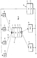
- each object is associated with an object-related electronic component 10, a so-called electronic TAG, which is firmly connected to the object.
- Each component 10 comprises a data processing device 12 with a data memory in which information about and for identification of the object are stored.
- the component 10 comprises a time base 13, an ultrasound receiver 11 for receiving ultrasound signals and a wireless communication device 14, in the form of a radio communication device, for transmitting and receiving radio signals.
- the system comprises a central component 20 which comprises a data processing device 21 and a time base 22 and which is connected to one or more stationary wireless communication devices 23, 24 in the form of radio communication devices and can receive and transmit via these radio signals.
- a central component 20 which comprises a data processing device 21 and a time base 22 and which is connected to one or more stationary wireless communication devices 23, 24 in the form of radio communication devices and can receive and transmit via these radio signals.
- a plurality of stationary ultrasonic transmitters 30, 31, 32, 40 are provided which are connected to and controlled by the central component 1.
- the US transmitters 30-32, 40 are arranged distributed over an area to be covered with US signals, with their position of the central components 20 is known exactly.
- the US stations 30-32, 40 are divided into groups. Each group comprises at least three US transmitters, e.g. US1-1, US2-1, US3-1, which transmit on a first US frequency f1.
- An adjacent group also includes several US transmitters, e.g. US2-1, ..., etc, which send on a second US frequency f2.
- the location of the object-related component 10 and thus of the object itself is carried out by means of a transit time measurement of the US transmitters 30-32, 40 radiated US signals to determine the distance between the attached to the object to be located US receiver and the fixed positions attached US transmitters 30-32, 40.
- a field strength measurement is made.
- the field strength of the radio transmitter radiated by the radio transmitter 14 attached to the radio object is measured at the radio receivers 23, 24. The greater the field strength, the closer the object to the corresponding radio receiver 23, 24.
- the transit times t1, t2, t3 of the ultrasonic signals from the individual stationary US transmitters 30-32, 40 to the US receiver 11 of the object-related component 10 are measured.
- Each run time can be assigned to a specific distance d1, d2, d3 between the US transmitter and the US receiver because of the known speed of sound (in air at room temperature about 344 m / s).
- the distances d1, d2, d3 can also already be calculated in the object-related component 10 and transmitted to the central component 20.
- the higher-level central component 20 thus coordinates the US transmitters 30-32, 40, synchronizes the time bases 13 on the object-related components and controls the communication between the object-related components 10 and the central component 20 via the wireless communication system 14, 23, 24.
- FIG. 2 It is shown that the assignment of a US signal received in the US receiver 11 to a specific US transmitter 30-32, 40 is effected by a time slot method.
- Each US transmitter US1, US2, US3 transmits its signal at the beginning of a specified time window.
- the respective transmission time of the US signals is from the controlled central component. For example, US1 in the time window sends 1, US2 in the time window 2, etc.
- the US signals of the US transmitters US1, US2, US3 are received in the US receiver UE.
- the time bases 13 of the object-related components and the central component 22 are synchronized with each other. This is done by replacing a synchronization protocol via the radio communication system.
- the US signals are received in the US receiver of the object related component 10.
- the propagation times of the US signals received in the respective time windows are calculated from the reception time and the time frame given by the time windows and stored in a broadcast telegram to be sent.
- any US signal received in the US receiver can be assigned to exactly one US transmitter based on the current time window.
- the stored broadcast telegrams are sent from the object-related components 10 and the central component.
- the US receiver only the first received US signal is received per time slot, i. the signal with the shortest runtime, evaluated.
- the length of a time slot results in the maximum possible distance between the US receiver on the object and the US transmitter.
- the maximum range of the US transmitter is about 10-15 m.
- the resolution of the time bases 13, 22 used and their synchrony determines the accuracy of the distance measurement and thus the precision of the localization. When determining the position accuracies in the range of a few centimeters can be achieved.
- the number of time slots determines the maximum number of possible US transmitters within the US range and thus limits the temporal resolution of the location, that is, the shortest time between two consecutive location determinations of a particular object.
- the central component can determine which group of US transmitters the object is closest to. If the object is exactly at the boundary between two groups of US stations, the acquired transit times t1, t2 and t3 can come from US stations of different groups. Since the US transmitters of adjacent groups with different frequencies send f1 and f2 respectively, the evaluation of the frequency makes it easy to determine from which group the single US signal originated.
- FIG. 3 shows a practical example of the time-division multiplexing method according to the invention.
- To the right is the time from 0 to 1 s in increments of 50 ms. At the bottom, the time from 0 to 12 s is shown in steps of 1 s.
- One cycle of time division multiplexing takes 10 s in this example. The cycle is divided into 200 time slots of 50 ms each.
- time synchronization windows S1... Sx are provided, in which a data transmission takes place between the central component 20 and the object-related component 10 for the purpose of synchronizing their time base 13.
- ultrasound transmission and reception windows U1... Uy are provided in which the transmission and reception of the US signals takes place.
- Each US transmitter transmits only one time slot Uy of one cycle.
- the radio communication takes place between the central component 20 and one or more specific object-related components 10.
- a series of broadcast windows B are provided, in which location messages containing the ultrasound transit time or distance values, respectively, over the radio communication system of the object-related Components 10 are transmitted to the central component.
- Each object-related component sends its location telegram, for example, three times in randomly selected broadcast windows, eg according to the slotted ALOHA method.
- the individual time synchronization windows, ultrasonic transmit and receive windows, communication windows and broadcast windows occur within a cycle in an in FIG. 3 shown order.
- a total of 36 US transmitters are provided, each transmitting in one of the 36 ultrasonic transmit and receive windows U1 ... U36.
Landscapes
- Physics & Mathematics (AREA)
- Engineering & Computer Science (AREA)
- General Physics & Mathematics (AREA)
- Radar, Positioning & Navigation (AREA)
- Remote Sensing (AREA)
- Measurement Of Velocity Or Position Using Acoustic Or Ultrasonic Waves (AREA)
- Radar Systems Or Details Thereof (AREA)
Claims (12)
- Procédé pour identifier et localiser des objets à l'intérieur d'une zone limitée,
selon lequel au moins un émetteur d'ultrasons (30-32) disposé fixe à l'intérieur de la zone émet un signal ultrasonore à un moment d'émission prédéfini,
le signal ultrasonore émis est reçu par un récepteur d'ultrasons (11) d'un composant (10) disposé dans/sur l'objet,
un moment de réception est affecté, dans le composant (10) relatif à l'objet, au signal ultrasonore reçu,
le moment de réception déterminé est transmis, avec une caractéristique d'identification de l'objet, à un composant central (20) par l'intermédiaire d'un système de communication sans fil (14 ; 23 ; 24),
on utilise comme système de communication sans fil un système de communication radio, des signaux radio étant échangés entre un émetteur/récepteur radio (14) disposé dans le composant relatif à l'objet et un émetteur/récepteur radio fixe (23, 24) relié au composant central,
dans le composant (10) relatif à l'objet et/ou dans le composant central (20), la durée de propagation du signal ultrasonore est déterminée à partir du moment d'émission et du moment de réception affecté,
à partir de la durée de propagation du signal ultrasonore est déterminée la distance entre l'émetteur d'ultrasons et l'émetteur d'ultrasons de l'objet,
à partir des distances déterminées, la position du récepteur d'ultrasons (11) et, ainsi, de l'objet est déterminée à l'aide de méthodes connues,
les émetteurs d'ultrasons sont disposés en deux groupes ou plus, tous les émetteurs d'ultrasons d'un même groupe émettant sur une fréquence d'émission définie (f1 ; f2),
caractérisé en ce que pour une localisation approximative d'un composant relatif à l'objet du côté du composant central l'intensité de champ de réception des signaux radio reçus par les émetteurs radio relatifs à l'objet est définie, et en ce que pour chaque groupe une fréquence d'émission différente de celle du groupe voisin est utilisée pour les émetteurs d'ultrasons, et en ce qu'à l'aide d'une mesure de fréquence des signaux ultrasonores reçus dans le récepteur d'ultrasons (11) relatif à l'objet, une distinction est faite en supplément entre les groupes voisins d'émetteurs d'ultrasons. - Procédé selon la revendication 1, caractérisé en ce que plusieurs émetteurs d'ultrasons (30-32) disposés fixes à l'intérieur de la zone émettent chacun à un moment d'émission prédéfini un signal ultrasonore, et une localisation bidimensionnelle ou tridimensionnelle de l'objet est réalisée.
- Procédé selon l'une des revendications 1 ou 2, caractérisé en ce que les moments d'émission pour les signaux ultrasonores des émetteurs d'ultrasons (30-32) individuels sont commandés par le composant central (20).
- Procédé selon l'une des revendications 1 à 3, caractérisé en ce qu'en même temps que les signaux ultrasonores, un signal radio est émis par l'un des émetteurs/récepteurs radio fixes, la mesure du temps de propagation pour les signaux ultrasonores émis démarrant grâce à la réception du signal radio dans le composant relatif à l'objet.
- Procédé selon l'une des revendications 1 à 4, caractérisé en ce que le composant central et le composant relatif à l'objet présentent des bases de temps (22 ; 13) respectives qui sont synchronisées de manière continue.
- Procédé selon la revendication 5, caractérisé en ce que la synchronisation des bases de temps (22 ; 13) se fait par l'intermédiaire du système de communication sans fil.
- Procédé selon l'une des revendications 5 ou 6, caractérisé en ce que l'émission des signaux ultrasonores se fait dans un cycle qui se répète sans cesse, étant précisé que le cycle est divisé en plusieurs intervalles de temps et qu'à chaque émetteur d'ultrasons est affecté un intervalle de temps à l'intérieur duquel il émet son signal ultrasonore.
- Procédé selon l'une des revendications 5 à 7, caractérisé en ce que la synchronisation des bases de temps se fait à l'intérieur d'un intervalle de temps défini.
- Procédé selon l'une des revendications 5 à 8, caractérisé en ce que les signaux ultrasonores reçus par le récepteur d'ultrasons sont affectés à l'émetteur respectif à l'aide de l'intervalle de temps qui est valable au moment de la réception.
- Procédé selon l'une des revendications 5 à 9, caractérisé en ce que le récepteur d'ultrasons n'analyse que le signal ultrasonore qui est reçu en premier à l'intérieur d'un intervalle de temps.
- Procédé selon l'une des revendications 1 à 10, caractérisé en ce que les émetteurs d'ultrasons d'un même groupe n'émettent jamais en même temps.
- Procédé selon l'une des revendications 7 à 11, caractérisé en ce que l'échange de signaux radio se fait à l'intérieur d'un intervalle de temps défini.
Applications Claiming Priority (2)
| Application Number | Priority Date | Filing Date | Title |
|---|---|---|---|
| DE10324651 | 2003-05-30 | ||
| DE10324651A DE10324651A1 (de) | 2003-05-30 | 2003-05-30 | Verfahren und System zur Identifikation und Ortsbestimmung von Objekten |
Publications (2)
| Publication Number | Publication Date |
|---|---|
| EP1482323A1 EP1482323A1 (fr) | 2004-12-01 |
| EP1482323B1 true EP1482323B1 (fr) | 2011-03-16 |
Family
ID=33103659
Family Applications (1)
| Application Number | Title | Priority Date | Filing Date |
|---|---|---|---|
| EP04012514A Expired - Lifetime EP1482323B1 (fr) | 2003-05-30 | 2004-05-27 | Procédé et dispositif d'identification et de localisation d'objets |
Country Status (3)
| Country | Link |
|---|---|
| EP (1) | EP1482323B1 (fr) |
| AT (1) | ATE502312T1 (fr) |
| DE (2) | DE10324651A1 (fr) |
Families Citing this family (4)
| Publication number | Priority date | Publication date | Assignee | Title |
|---|---|---|---|---|
| DE102006044937B4 (de) * | 2006-09-22 | 2012-03-01 | Pepperl + Fuchs Gmbh | Vorrichtung und Verfahren zur Bestimmung der Entfernung und/oder der Raumposition eines Zielobjekts |
| GB2457600A (en) * | 2009-03-03 | 2009-08-26 | Saturn Solutions Ltd | Vehicle measurement system |
| DE102009031955B4 (de) | 2009-06-08 | 2014-04-30 | Technische Universität Dresden | Verfahren und Vorrichtung zur Bestimmung der räumlichen Position einer zu ortenden Einheit |
| ITMO20120157A1 (it) * | 2012-06-18 | 2013-12-19 | Microlog S R L | Sistema e metodo per il monitoraggio di flussi di persone |
Family Cites Families (9)
| Publication number | Priority date | Publication date | Assignee | Title |
|---|---|---|---|---|
| US5214615A (en) * | 1990-02-26 | 1993-05-25 | Will Bauer | Three-dimensional displacement of a body with computer interface |
| DE4036022A1 (de) * | 1990-11-13 | 1992-05-14 | Bosch Gmbh Robert | Verfahren und ortungseinrichtung zur ortung von fahrzeugen fahrerloser transportsysteme |
| DE4119150A1 (de) * | 1991-06-11 | 1992-12-17 | Brunner Wolfgang | Messanordnung fuer die ganganalyse |
| US5412619A (en) * | 1994-04-14 | 1995-05-02 | Bauer; Will | Three-dimensional displacement of a body with computer interface |
| JPH0996672A (ja) * | 1995-09-29 | 1997-04-08 | Sukuuea:Kk | 3次元位置データ生成システムおよび方法 |
| GB2332053B (en) * | 1997-12-04 | 2002-01-09 | Olivetti Res Ltd | Detection system for determinning positional and other information about objects |
| IL122079A (en) * | 1997-10-30 | 2002-02-10 | Netmor Ltd | Ultrasound system for positioning and tracking |
| US6292106B1 (en) * | 1998-10-13 | 2001-09-18 | Cubic Defense Systems, Inc. | Acoustical system and method for simultaneously locating and tracking multiple personnel in rooms of a building |
| US6532416B1 (en) * | 2000-05-23 | 2003-03-11 | Siemens Aktiengesellschaft | Apparatus, method and system for a wireless communication and local positioning system in an automated, industrial and/or manufacturing environment |
-
2003
- 2003-05-30 DE DE10324651A patent/DE10324651A1/de not_active Ceased
-
2004
- 2004-05-27 AT AT04012514T patent/ATE502312T1/de active
- 2004-05-27 DE DE502004012298T patent/DE502004012298D1/de not_active Expired - Lifetime
- 2004-05-27 EP EP04012514A patent/EP1482323B1/fr not_active Expired - Lifetime
Also Published As
| Publication number | Publication date |
|---|---|
| ATE502312T1 (de) | 2011-04-15 |
| DE10324651A1 (de) | 2004-12-23 |
| DE502004012298D1 (de) | 2011-04-28 |
| EP1482323A1 (fr) | 2004-12-01 |
Similar Documents
| Publication | Publication Date | Title |
|---|---|---|
| DE10055289B4 (de) | System zur Bestimmung der Position eines Objekts | |
| DE69223405T2 (de) | Positionsbestimmungssystem auf Abstand | |
| DE60212580T2 (de) | Ortungssystem und Verfahren | |
| EP3519851B1 (fr) | Localisation basée sur une division de télégrammes | |
| EP2845026B1 (fr) | Procédé et ensemble pour la détection relative de position de stations par radiolocalisation | |
| DE69027872T2 (de) | System zum Folgen eines Flugzeuges über einer Fläche. | |
| DE102008010882A1 (de) | Vorrichtung und Verfahren zur Richtungsschätzung und/oder Decodierung von Sekundärradarsignalen | |
| EP3414591A1 (fr) | Dispositif de représentation d'informations d'utilisateur et procédé correspondant | |
| DE102013019647A1 (de) | Indoor-Positionsbestimmung mittels Kamera und optischem Signal | |
| DE112005003895B4 (de) | Verfahren zur Synchronisation von Takteinrichtungen | |
| DE102017209092A1 (de) | Verfahren und Vorrichtung zur Lokalisierung eines Fahrzeugs für eine induktive Energieübertragung | |
| EP3146355B1 (fr) | Système d'appareils médicaux et procédé pour localiser des appareils médicaux et des unités de commande mobiles de ce système d'appareils médicaux | |
| EP1482323A1 (fr) | Procédé et dispositif d'identification et de localisation d'objets | |
| DE10142156B4 (de) | Mobile Navigationsvorrichtung für ein zellulares Funknetz sowie Verfahren zum Liefern von Navigationsinformationen | |
| EP2182376B1 (fr) | Procédé de détermination de position | |
| EP3864426B1 (fr) | Système et procédé de détermination de la position dans un bâtiment | |
| DE102009031955B4 (de) | Verfahren und Vorrichtung zur Bestimmung der räumlichen Position einer zu ortenden Einheit | |
| DE102017118324B4 (de) | Anordnung und Verfahren zur Abstandsmessung zwischen Geräten in einem Funksystem | |
| DE102019211812A1 (de) | Verfahren zur Ortung eines Objekts | |
| DE102017131117A1 (de) | Drahtloses, elektronisches Lokalisierungssystem | |
| DE20114245U1 (de) | Mobile Navigationsvorrichtung für ein zellulares Funknetz | |
| EP2465310A1 (fr) | Procédé et agencement pour la mesure de la durée de propagation d'un signal entre deux stations de l'agencement | |
| DE102017125332B4 (de) | Verfahren und System zur Positionsbestimmung einer mobilen Vorrichtung mittels Kartenabgleich | |
| DE102023205197B3 (de) | Kommunikationsschema für ein Nahbereichsfunksystem, und Nahbereichsfunksystem, welches das Kommunikationsschema verwendet | |
| DE102016213239B4 (de) | Vorrichtung zur kommunikation mit kommunikationsvorrichtungen, entsprechende kommunikationsvorrichtung und verfahren |
Legal Events
| Date | Code | Title | Description |
|---|---|---|---|
| PUAI | Public reference made under article 153(3) epc to a published international application that has entered the european phase |
Free format text: ORIGINAL CODE: 0009012 |
|
| AK | Designated contracting states |
Kind code of ref document: A1 Designated state(s): AT BE BG CH CY CZ DE DK EE ES FI FR GB GR HU IE IT LI LU MC NL PL PT RO SE SI SK TR |
|
| AX | Request for extension of the european patent |
Extension state: AL HR LT LV MK |
|
| 17P | Request for examination filed |
Effective date: 20050330 |
|
| AKX | Designation fees paid |
Designated state(s): AT BE BG CH CY CZ DE DK EE ES FI FR GB GR HU IE IT LI LU MC NL PL PT RO SE SI SK TR |
|
| 17Q | First examination report despatched |
Effective date: 20081114 |
|
| GRAP | Despatch of communication of intention to grant a patent |
Free format text: ORIGINAL CODE: EPIDOSNIGR1 |
|
| GRAS | Grant fee paid |
Free format text: ORIGINAL CODE: EPIDOSNIGR3 |
|
| GRAA | (expected) grant |
Free format text: ORIGINAL CODE: 0009210 |
|
| AK | Designated contracting states |
Kind code of ref document: B1 Designated state(s): AT BE BG CH CY CZ DE DK EE ES FI FR GB GR HU IE IT LI LU MC NL PL PT RO SE SI SK TR |
|
| REG | Reference to a national code |
Ref country code: GB Ref legal event code: FG4D Free format text: NOT ENGLISH |
|
| REG | Reference to a national code |
Ref country code: CH Ref legal event code: EP |
|
| REG | Reference to a national code |
Ref country code: IE Ref legal event code: FG4D |
|
| REF | Corresponds to: |
Ref document number: 502004012298 Country of ref document: DE Date of ref document: 20110428 Kind code of ref document: P |
|
| REG | Reference to a national code |
Ref country code: DE Ref legal event code: R096 Ref document number: 502004012298 Country of ref document: DE Effective date: 20110428 |
|
| REG | Reference to a national code |
Ref country code: NL Ref legal event code: VDEP Effective date: 20110316 |
|
| PG25 | Lapsed in a contracting state [announced via postgrant information from national office to epo] |
Ref country code: SE Free format text: LAPSE BECAUSE OF FAILURE TO SUBMIT A TRANSLATION OF THE DESCRIPTION OR TO PAY THE FEE WITHIN THE PRESCRIBED TIME-LIMIT Effective date: 20110316 Ref country code: GR Free format text: LAPSE BECAUSE OF FAILURE TO SUBMIT A TRANSLATION OF THE DESCRIPTION OR TO PAY THE FEE WITHIN THE PRESCRIBED TIME-LIMIT Effective date: 20110617 Ref country code: ES Free format text: LAPSE BECAUSE OF FAILURE TO SUBMIT A TRANSLATION OF THE DESCRIPTION OR TO PAY THE FEE WITHIN THE PRESCRIBED TIME-LIMIT Effective date: 20110627 |
|
| PG25 | Lapsed in a contracting state [announced via postgrant information from national office to epo] |
Ref country code: BG Free format text: LAPSE BECAUSE OF FAILURE TO SUBMIT A TRANSLATION OF THE DESCRIPTION OR TO PAY THE FEE WITHIN THE PRESCRIBED TIME-LIMIT Effective date: 20110616 Ref country code: FI Free format text: LAPSE BECAUSE OF FAILURE TO SUBMIT A TRANSLATION OF THE DESCRIPTION OR TO PAY THE FEE WITHIN THE PRESCRIBED TIME-LIMIT Effective date: 20110316 Ref country code: CY Free format text: LAPSE BECAUSE OF FAILURE TO SUBMIT A TRANSLATION OF THE DESCRIPTION OR TO PAY THE FEE WITHIN THE PRESCRIBED TIME-LIMIT Effective date: 20110316 Ref country code: SI Free format text: LAPSE BECAUSE OF FAILURE TO SUBMIT A TRANSLATION OF THE DESCRIPTION OR TO PAY THE FEE WITHIN THE PRESCRIBED TIME-LIMIT Effective date: 20110316 |
|
| REG | Reference to a national code |
Ref country code: IE Ref legal event code: FD4D |
|
| PG25 | Lapsed in a contracting state [announced via postgrant information from national office to epo] |
Ref country code: IE Free format text: LAPSE BECAUSE OF FAILURE TO SUBMIT A TRANSLATION OF THE DESCRIPTION OR TO PAY THE FEE WITHIN THE PRESCRIBED TIME-LIMIT Effective date: 20110316 Ref country code: PT Free format text: LAPSE BECAUSE OF FAILURE TO SUBMIT A TRANSLATION OF THE DESCRIPTION OR TO PAY THE FEE WITHIN THE PRESCRIBED TIME-LIMIT Effective date: 20110718 Ref country code: EE Free format text: LAPSE BECAUSE OF FAILURE TO SUBMIT A TRANSLATION OF THE DESCRIPTION OR TO PAY THE FEE WITHIN THE PRESCRIBED TIME-LIMIT Effective date: 20110316 |
|
| BERE | Be: lapsed |
Owner name: IDENTEC SOLUTIONS AG Effective date: 20110531 |
|
| PG25 | Lapsed in a contracting state [announced via postgrant information from national office to epo] |
Ref country code: RO Free format text: LAPSE BECAUSE OF FAILURE TO SUBMIT A TRANSLATION OF THE DESCRIPTION OR TO PAY THE FEE WITHIN THE PRESCRIBED TIME-LIMIT Effective date: 20110316 Ref country code: SK Free format text: LAPSE BECAUSE OF FAILURE TO SUBMIT A TRANSLATION OF THE DESCRIPTION OR TO PAY THE FEE WITHIN THE PRESCRIBED TIME-LIMIT Effective date: 20110316 Ref country code: CZ Free format text: LAPSE BECAUSE OF FAILURE TO SUBMIT A TRANSLATION OF THE DESCRIPTION OR TO PAY THE FEE WITHIN THE PRESCRIBED TIME-LIMIT Effective date: 20110316 |
|
| PG25 | Lapsed in a contracting state [announced via postgrant information from national office to epo] |
Ref country code: NL Free format text: LAPSE BECAUSE OF FAILURE TO SUBMIT A TRANSLATION OF THE DESCRIPTION OR TO PAY THE FEE WITHIN THE PRESCRIBED TIME-LIMIT Effective date: 20110316 Ref country code: MC Free format text: LAPSE BECAUSE OF NON-PAYMENT OF DUE FEES Effective date: 20110531 |
|
| REG | Reference to a national code |
Ref country code: CH Ref legal event code: PL |
|
| PLBE | No opposition filed within time limit |
Free format text: ORIGINAL CODE: 0009261 |
|
| STAA | Information on the status of an ep patent application or granted ep patent |
Free format text: STATUS: NO OPPOSITION FILED WITHIN TIME LIMIT |
|
| PG25 | Lapsed in a contracting state [announced via postgrant information from national office to epo] |
Ref country code: LI Free format text: LAPSE BECAUSE OF NON-PAYMENT OF DUE FEES Effective date: 20110531 Ref country code: CH Free format text: LAPSE BECAUSE OF NON-PAYMENT OF DUE FEES Effective date: 20110531 |
|
| 26N | No opposition filed |
Effective date: 20111219 |
|
| PG25 | Lapsed in a contracting state [announced via postgrant information from national office to epo] |
Ref country code: PL Free format text: LAPSE BECAUSE OF FAILURE TO SUBMIT A TRANSLATION OF THE DESCRIPTION OR TO PAY THE FEE WITHIN THE PRESCRIBED TIME-LIMIT Effective date: 20110316 Ref country code: DK Free format text: LAPSE BECAUSE OF FAILURE TO SUBMIT A TRANSLATION OF THE DESCRIPTION OR TO PAY THE FEE WITHIN THE PRESCRIBED TIME-LIMIT Effective date: 20110316 |
|
| PG25 | Lapsed in a contracting state [announced via postgrant information from national office to epo] |
Ref country code: BE Free format text: LAPSE BECAUSE OF NON-PAYMENT OF DUE FEES Effective date: 20110531 |
|
| REG | Reference to a national code |
Ref country code: DE Ref legal event code: R097 Ref document number: 502004012298 Country of ref document: DE Effective date: 20111219 |
|
| REG | Reference to a national code |
Ref country code: AT Ref legal event code: MM01 Ref document number: 502312 Country of ref document: AT Kind code of ref document: T Effective date: 20110527 |
|
| PG25 | Lapsed in a contracting state [announced via postgrant information from national office to epo] |
Ref country code: AT Free format text: LAPSE BECAUSE OF NON-PAYMENT OF DUE FEES Effective date: 20110527 |
|
| PG25 | Lapsed in a contracting state [announced via postgrant information from national office to epo] |
Ref country code: LU Free format text: LAPSE BECAUSE OF NON-PAYMENT OF DUE FEES Effective date: 20110527 |
|
| PG25 | Lapsed in a contracting state [announced via postgrant information from national office to epo] |
Ref country code: TR Free format text: LAPSE BECAUSE OF FAILURE TO SUBMIT A TRANSLATION OF THE DESCRIPTION OR TO PAY THE FEE WITHIN THE PRESCRIBED TIME-LIMIT Effective date: 20110316 |
|
| PG25 | Lapsed in a contracting state [announced via postgrant information from national office to epo] |
Ref country code: HU Free format text: LAPSE BECAUSE OF FAILURE TO SUBMIT A TRANSLATION OF THE DESCRIPTION OR TO PAY THE FEE WITHIN THE PRESCRIBED TIME-LIMIT Effective date: 20110316 |
|
| REG | Reference to a national code |
Ref country code: FR Ref legal event code: PLFP Year of fee payment: 13 |
|
| REG | Reference to a national code |
Ref country code: FR Ref legal event code: PLFP Year of fee payment: 14 |
|
| PGFP | Annual fee paid to national office [announced via postgrant information from national office to epo] |
Ref country code: GB Payment date: 20170524 Year of fee payment: 14 Ref country code: DE Payment date: 20170522 Year of fee payment: 14 Ref country code: FR Payment date: 20170522 Year of fee payment: 14 |
|
| PGFP | Annual fee paid to national office [announced via postgrant information from national office to epo] |
Ref country code: IT Payment date: 20170524 Year of fee payment: 14 |
|
| REG | Reference to a national code |
Ref country code: DE Ref legal event code: R119 Ref document number: 502004012298 Country of ref document: DE |
|
| GBPC | Gb: european patent ceased through non-payment of renewal fee |
Effective date: 20180527 |
|
| PG25 | Lapsed in a contracting state [announced via postgrant information from national office to epo] |
Ref country code: IT Free format text: LAPSE BECAUSE OF NON-PAYMENT OF DUE FEES Effective date: 20180527 Ref country code: DE Free format text: LAPSE BECAUSE OF NON-PAYMENT OF DUE FEES Effective date: 20181201 Ref country code: FR Free format text: LAPSE BECAUSE OF NON-PAYMENT OF DUE FEES Effective date: 20180531 Ref country code: GB Free format text: LAPSE BECAUSE OF NON-PAYMENT OF DUE FEES Effective date: 20180527 |