EP1482531B1 - Magnetron - Google Patents
Magnetron Download PDFInfo
- Publication number
- EP1482531B1 EP1482531B1 EP04250016A EP04250016A EP1482531B1 EP 1482531 B1 EP1482531 B1 EP 1482531B1 EP 04250016 A EP04250016 A EP 04250016A EP 04250016 A EP04250016 A EP 04250016A EP 1482531 B1 EP1482531 B1 EP 1482531B1
- Authority
- EP
- European Patent Office
- Prior art keywords
- vanes
- positive polar
- polar body
- magnetron
- electric field
- Prior art date
- Legal status (The legal status is an assumption and is not a legal conclusion. Google has not performed a legal analysis and makes no representation as to the accuracy of the status listed.)
- Expired - Lifetime
Links
Images


Classifications
-
- H—ELECTRICITY
- H01—ELECTRIC ELEMENTS
- H01J—ELECTRIC DISCHARGE TUBES OR DISCHARGE LAMPS
- H01J23/00—Details of transit-time tubes of the types covered by group H01J25/00
- H01J23/02—Electrodes; Magnetic control means; Screens
- H01J23/04—Cathodes
- H01J23/05—Cathodes having a cylindrical emissive surface, e.g. cathodes for magnetrons
-
- H—ELECTRICITY
- H01—ELECTRIC ELEMENTS
- H01J—ELECTRIC DISCHARGE TUBES OR DISCHARGE LAMPS
- H01J25/00—Transit-time tubes, e.g. klystrons, travelling-wave tubes, magnetrons
- H01J25/50—Magnetrons, i.e. tubes with a magnet system producing an H-field crossing the E-field
- H01J25/52—Magnetrons, i.e. tubes with a magnet system producing an H-field crossing the E-field with an electron space having a shape that does not prevent any electron from moving completely around the cathode or guide electrode
- H01J25/58—Magnetrons, i.e. tubes with a magnet system producing an H-field crossing the E-field with an electron space having a shape that does not prevent any electron from moving completely around the cathode or guide electrode having a number of resonators; having a composite resonator, e.g. a helix
- H01J25/587—Multi-cavity magnetrons
-
- H—ELECTRICITY
- H01—ELECTRIC ELEMENTS
- H01J—ELECTRIC DISCHARGE TUBES OR DISCHARGE LAMPS
- H01J23/00—Details of transit-time tubes of the types covered by group H01J25/00
- H01J23/16—Circuit elements, having distributed capacitance and inductance, structurally associated with the tube and interacting with the discharge
- H01J23/18—Resonators
- H01J23/20—Cavity resonators; Adjustment or tuning thereof
-
- H—ELECTRICITY
- H01—ELECTRIC ELEMENTS
- H01J—ELECTRIC DISCHARGE TUBES OR DISCHARGE LAMPS
- H01J23/00—Details of transit-time tubes of the types covered by group H01J25/00
- H01J23/16—Circuit elements, having distributed capacitance and inductance, structurally associated with the tube and interacting with the discharge
- H01J23/18—Resonators
- H01J23/20—Cavity resonators; Adjustment or tuning thereof
- H01J23/213—Simultaneous tuning of more than one resonator, e.g. resonant cavities of a magnetron
-
- H—ELECTRICITY
- H01—ELECTRIC ELEMENTS
- H01J—ELECTRIC DISCHARGE TUBES OR DISCHARGE LAMPS
- H01J23/00—Details of transit-time tubes of the types covered by group H01J25/00
- H01J23/16—Circuit elements, having distributed capacitance and inductance, structurally associated with the tube and interacting with the discharge
- H01J23/18—Resonators
- H01J23/22—Connections between resonators, e.g. strapping for connecting resonators of a magnetron
Definitions
- the present invention relates, in general, to a magnetron and, more particularly, to a magnetron, in which a plurality of vanes positioned between a positive polar body and a negative polar section are radially arranged toward a central axis of the positive polar body, thereby generating microwaves.
- magnetrons are high-frequency generators, and are widely used to generate microwaves in home appliances, such as microwave ovens, as well as in industrial applications, such as high-frequency heating apparatuses, particle accelerators and radars.
- a magnetron a plurality of vanes are arranged in a cylindrically shaped positive polar body toward a central axis of the positive polar body, and a negative polar section to emit thermions is positioned in the central axis of the positive polar body.
- a filament of the negative polar section is heated and then the thermions are continuously emitted from the heated filament, so that a series of thermions are formed. Thereafter, the series of thermions are brought into contact with surfaces of inner ends of the vanes, after rotating around the filament and moving toward the surfaces of the inner ends of the vanes under the influence of an electric field and a magnetic field formed in an activating space defined between the filament and vanes.
- the series of thermions generate an electrical potential difference caused by alternating polarities in every two neighboring vanes.
- oscillations are continuously generated by electrical potential differences of alternating polarities in a plurality of resonant circuits formed between the positive polar body and the plurality of vanes, so that microwaves corresponding to a rotation speed of the series of thermions are generated.
- the two neighboring vanes and a portion of the positive polar body connecting the two neighboring vanes to each other form a resonant circuit.
- electric charges move through the two neighboring vanes and the portion of the positive polar body connecting the two neighboring vanes to each other, and a movement direction of the electric charges is periodically and alternately changed.
- a frequency of the microwaves generated in the magnetron is determined by an alternation period of the movement direction of the electric charges.
- undesirable harmonics may be generated in the microwaves generated in the magnetron, especially if a distribution of an electric field is not uniform on surfaces of outer ends of the vanes.
- US 2 950 416 discloses a means for reducing the incidence of undesired frequencies, or modes of oscillation in the operation of a magnetron.
- the means comprises introducing a flux-linking energy-shunting element in the form of a loop of lossy material extending into a central slot in one or more vanes.
- US-2003/009 022 0 A1 , DE-012 51 540 , and GB-235 7 629 A disclose magnetrons having radially arranged vanes with grooves or cut-away portions on the outer radial ends thereof.
- An aim of the present invention is to provide a magnetron, in which a construction of outer ends of vanes brought into contact with a positive polar body is improved to make a distribution of an electric field uniform, thereby decreasing generation of undesirable harmonics.
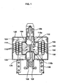
- FIG. 1 is a sectional view of a magnetron, according to the embodiment of the present invention.
- a plurality of vanes 104 which constitute a positive polar section together with a positive polar body 102, are radially arranged at regular intervals toward a central axis of the positive polar body 102, thus forming resonant circuits.
- An antenna 106 is connected to one of the vanes 104 to lead microwaves to the outside.
- Semi-circularly shaped electric field adjusting grooves 150 are provided on surfaces of outer ends of the vanes 104 brought into contact with the positive polar body 102.
- the electric field adjusting grooves 150 allow a distribution of an electric field to be uniform in the vanes 104.
- the vanes 104 are arranged to be alternately connected to one another by two straps 116 placed in each of upper and lower portions of the vanes 104.
- a negative polar section, including a coil spring-shaped filament 112, to emit thermions at a high temperature is disposed in a central axis of the positive polar body 102, and an activating space 114 is defined between the filament 112 and inner ends of the vanes 104.
- An upper shield 118a and a lower shield 118b are attached onto a top and a bottom of the filament 112, respectively.
- a center lead 120 is fixedly welded to a bottom of the upper shield 118a while being passed through a through hole of the lower shield 118b and the filament 112.
- a side lead 122 is welded to a bottom of the lower shield 118b.
- the center lead 120 and the side lead 122 are electrically connected to an external power source (not shown), and form an electric field in the activating space 114 defined between the filament 112 and the inner ends of the vanes 104.
- An upper permanent magnet 124 and a lower permanent magnet 126 are attached onto a top and bottom of the positive polar section, respectively, with opposite magnetic poles of the upper and lower permanent magnets 124 and 126 facing each other.
- the permanent magnets 124 and 126 provide a magnetic flux to the activating space 114.
- An upper pole piece 134 and a lower pole piece 136 are disposed in upper and lower portions of the positive polar body 102, respectively, to lead the magnetic flux generated by the upper and lower permanent magnets 124 and 126 into the activating space 114.
- Upper and lower yokes 128 and 130 are disposed to surround the above-described elements.
- the upper and lower yokes 128 and 130 are magnetically connected to each other and form a magnetic circuit that connects the upper permanent magnet 124 and the lower permanent magnet 126 to each other.
- the filament 112 When power is supplied from the external power supply unit to the filament 112, the filament 112 is heated and thermions are continuously emitted from the heated filament 112, so that a series of thermions is formed.
- the series of thermions are brought into contact with the inner ends of the vanes 104 after rotating around the filament 112 and moving toward the inner ends of the vanes 104 under the influence of an electric field and a magnetic field formed in the activating space 114, thus generating an electrical potential difference caused by alternating polarities formed in two neighboring vanes 104.
- oscillations are continuously generated by electrical potential differences caused by alternating polarities in a plurality of resonant circuits formed between the positive polar body 102 and the plurality of vanes 104, so that microwaves corresponding to a rotation speed of the series of thermions are generated and transmitted to the outside through an antenna 106.
- Figure 2 is a view showing construction of the positive polar body 102, vanes 104, and straps 116a through 116d of the magnetron, according to the embodiment of the present invention as shown in Figure 1 .
- an even number of vanes having the same shape are radially arranged so that surfaces of outer ends thereof are brought into contact with the inner surface of the cylindrically shaped positive polar body 102, and neighboring vanes 104 are arranged in an inverted relation to each other. That is, referring to two neighboring vanes 104a and 104b in Figure 2 , it is understood that the two vanes 104a and 104b are arranged to be in the inverted relation to each other.
- an antenna connecting portion 202a is upwardly open, and an electric field adjusting groove 150a is positioned on an upper portion of a surface of an outer end of the vane 104a.
- an antenna connecting portion 202b is downwardly open, and an electric field adjusting groove 150b is positioned on a lower portion of a surface of an outer end of the vane 104b.
- Each of the vanes 104 is electrically connected to upper straps 116a and 116b and lower straps 116c and 116d.
- the upper straps 116a and 116b are divided into an outer, upper strap 116a and an inner, upper strap 116b.
- the outer, upper strap 116a electrically connects odd numbered vanes 104 to each other and the inner, upper strap 116b electrically connects even numbered vanes 104 to each other.
- Figure 3 is a view showing distribution of moving electric charges in the two neighboring vanes 104a and 104b of the magnetron and the positive polar body 102 connecting the two neighboring vanes 104a and 104b to each other, according to the embodiment of the present invention as shown in Figure 2 .
- This drawing is a development view, in which the two vanes 104a and 104b are spread around a portion of the positive polar body 102 in a horizontal direction while being viewed from the central axis of the positive polar body 102 to the positive polar body 102.
- the electric charges moving through the upper portion of the vane 104a move toward the positive polar body 102 while being dispersed above and below the electric field adjusting groove 150a provided on the vane 104a.
- the dispersed electric charges are gathered and then move to the neighboring vane 104b.
- a path of the moving electric charges is longer than those of electric charges in other parts of the vane 104a.
- a magnitude of the electric field is decreased in the vicinity of the electric field adjusting groove 150a. Due to uniform construction of the two vanes 104a and 104b, the operations of the electric field adjusting grooves 150a and 150b are the same in the case where the electric charges move in a reverse direction.
- Figure 4 is a characteristic curve of a distribution (magnitudes) of electric fields along lengths of the surfaces of the outer ends of the vanes 104a and 104b in the magnetron, according to the embodiment of the present invention as shown in Figure 1 .
- upper and lower ends of the outer ends of the vanes 104a and 104b are represented by B and A', and A and B', respectively.
- a characteristic curve 402 representing a distribution of an electric field on surfaces of outer ends of conventional vanes having no electric field adjusting grooves, it may be understood that the distribution of the electric field is not uniform and a high electric field is formed at the upper end B and the lower end B'. Due to non-uniformity of the distribution of the electric field, harmonics are generated.
- a characteristic curve 404 representing the distribution of an electric field on the surfaces of the outer ends of the vanes 104a and 104b having electric field adjusting grooves 150a and 150b, it is understood that the distribution of the electric field on the surfaces of the outer ends extending from A to B and from A' to B' is uniform.
- the present invention provides a microwave oven, in which construction of the outer ends of the vanes are improved, thereby suppressing generation of undesirable harmonic waves.
Landscapes
- Microwave Tubes (AREA)
Claims (4)
- Magnetron, umfassend:einen positiven Polkörper (102); undmehrere Flügel (104), die mit einer Fläche eines ihrer Außenenden mit einer Innenfläche des positiven Polkörpers (102) verbunden sind und radial in Richtung einer Mittelachse des positiven Polkörpers angeordnet sind;dadurch gekennzeichnet, dass:jeder der Flügel (104) in einem oberen Abschnitt oder einem unteren Abschnitt an der Fläche seines Außenendes derart mit einer Nut (150) versehen ist, dass die Nuten in benachbarten Flügeln in umgekehrter Beziehung zueinander liegen.
- Magnetron nach Anspruch 1, wobei die Nut (150) halbkreisförmig ist.
- Magnetron nach einem der vorhergehenden Ansprüche, wobei jeder Flügel (104) ferner Folgendes umfasst:ein Antennenverbindungsteil (202a/b) zur Ermöglichung der Verbindung einer Antenne mit jedem Flügel, wobei das Antennenverbindungsteil selektiv entweder an einer oberen oder einer unteren Fläche des Flügels (104) derart vorgesehen ist, dass, wenn sich die Nut im oberen Teil befindet, das Antennenverbindungsteil nach oben offen ist und, wenn sich die Nut im unteren Teil befindet, das Antennenverbindungsteil nach unten offen ist.
- Magnetron nach einem der vorhergehenden Ansprüche, ferner Folgendes umfassend:einen negativen Polabschnitt auf der Mittelachse des positiven Polkörpers (102);eine Antenne (106), die mit einem der mehreren Flügel (104) verbunden ist; undmagnetischen Materialien (124, 126) zur Bildung eines Magnetfelds in dem positiven Polkörper (102).
Applications Claiming Priority (2)
| Application Number | Priority Date | Filing Date | Title |
|---|---|---|---|
| KR1020030034550A KR100913145B1 (ko) | 2003-05-29 | 2003-05-29 | 마그네트론 |
| KR2003034550 | 2003-05-29 |
Publications (3)
| Publication Number | Publication Date |
|---|---|
| EP1482531A2 EP1482531A2 (de) | 2004-12-01 |
| EP1482531A3 EP1482531A3 (de) | 2008-02-20 |
| EP1482531B1 true EP1482531B1 (de) | 2009-09-23 |
Family
ID=33129052
Family Applications (1)
| Application Number | Title | Priority Date | Filing Date |
|---|---|---|---|
| EP04250016A Expired - Lifetime EP1482531B1 (de) | 2003-05-29 | 2004-01-05 | Magnetron |
Country Status (6)
| Country | Link |
|---|---|
| US (1) | US7135820B2 (de) |
| EP (1) | EP1482531B1 (de) |
| JP (1) | JP3996130B2 (de) |
| KR (1) | KR100913145B1 (de) |
| CN (1) | CN100472703C (de) |
| DE (1) | DE602004023250D1 (de) |
Families Citing this family (6)
| Publication number | Priority date | Publication date | Assignee | Title |
|---|---|---|---|---|
| JP4503639B2 (ja) * | 2007-09-11 | 2010-07-14 | 東芝ホクト電子株式会社 | 電子レンジ用マグネトロン |
| GB2457046A (en) * | 2008-01-30 | 2009-08-05 | E2V Tech | Anode structure for a magnetron |
| WO2010097882A1 (ja) * | 2009-02-27 | 2010-09-02 | パナソニック株式会社 | マグネトロン及びマイクロ波利用機器 |
| JP5805842B1 (ja) | 2014-12-03 | 2015-11-10 | 東芝ホクト電子株式会社 | マグネトロン |
| CN108834301B (zh) * | 2018-06-27 | 2020-03-24 | 中国原子能科学研究院 | 同步回旋加速器中旋转电容转子的电接触方法及其结构 |
| CN115836376B (zh) * | 2020-07-29 | 2025-07-18 | 松下知识产权经营株式会社 | 磁控管 |
Family Cites Families (11)
| Publication number | Priority date | Publication date | Assignee | Title |
|---|---|---|---|---|
| US2950416A (en) * | 1957-02-15 | 1960-08-23 | William C Brown | Magnetron output control |
| CA1033461A (en) * | 1975-08-07 | 1978-06-20 | Her Majesty In Right Of Canada As Represented By Atomic Energy Of Canada Limited | High power doubly strapped vane type magnetron |
| US5003223A (en) * | 1987-08-19 | 1991-03-26 | Hitachi, Ltd. | Structure of anode of magnetron and a method of manufacturing the same |
| JPH01251540A (ja) * | 1988-03-31 | 1989-10-06 | Toshiba Corp | 電子レンジ用マグネトロン |
| KR930006440Y1 (ko) * | 1991-04-15 | 1993-09-24 | 주식회사 금성사 | 전자렌지용 마그네트론의 양극부구조 |
| KR940005989Y1 (ko) * | 1991-11-20 | 1994-08-31 | 주식회사 금성사 | 전자레인지용 마그네트론 |
| KR0116002Y1 (ko) * | 1994-07-18 | 1998-04-17 | 배순훈 | 납땜용 홈이 형성된 베인 |
| JPH11149879A (ja) | 1997-11-14 | 1999-06-02 | Toshiba Hokuto Electronics Corp | 電子レンジ用マグネトロン |
| GB2357629B (en) * | 1999-12-21 | 2004-06-09 | Marconi Applied Techn Ltd | Magnetron Anodes |
| JP4006980B2 (ja) * | 2001-11-09 | 2007-11-14 | 松下電器産業株式会社 | マグネトロン装置 |
| KR100482826B1 (ko) * | 2002-09-26 | 2005-04-14 | 삼성전자주식회사 | 마그네트론 |
-
2003
- 2003-05-29 KR KR1020030034550A patent/KR100913145B1/ko not_active Expired - Fee Related
- 2003-12-10 CN CNB2003101201809A patent/CN100472703C/zh not_active Expired - Fee Related
- 2003-12-22 US US10/740,827 patent/US7135820B2/en not_active Expired - Lifetime
-
2004
- 2004-01-05 EP EP04250016A patent/EP1482531B1/de not_active Expired - Lifetime
- 2004-01-05 DE DE602004023250T patent/DE602004023250D1/de not_active Expired - Lifetime
- 2004-01-20 JP JP2004012388A patent/JP3996130B2/ja not_active Expired - Fee Related
Also Published As
| Publication number | Publication date |
|---|---|
| EP1482531A3 (de) | 2008-02-20 |
| EP1482531A2 (de) | 2004-12-01 |
| JP3996130B2 (ja) | 2007-10-24 |
| CN1574168A (zh) | 2005-02-02 |
| KR100913145B1 (ko) | 2009-08-19 |
| JP2004356088A (ja) | 2004-12-16 |
| US20040239255A1 (en) | 2004-12-02 |
| CN100472703C (zh) | 2009-03-25 |
| DE602004023250D1 (de) | 2009-11-05 |
| KR20040102844A (ko) | 2004-12-08 |
| US7135820B2 (en) | 2006-11-14 |
Similar Documents
| Publication | Publication Date | Title |
|---|---|---|
| KR100866233B1 (ko) | 마그네트론 | |
| EP1482531B1 (de) | Magnetron | |
| US7026762B2 (en) | Magnetron, and microwave oven and high-frequency heating apparatus each equipped with the same | |
| EP1403899A2 (de) | Magnetron für Mikrowellenherde | |
| EP1505628A2 (de) | Magnetron | |
| KR100519265B1 (ko) | 마그네트론 | |
| EP1403900A2 (de) | Magnetron eines Mikrowellenofens | |
| EP1388879A2 (de) | Magnetron | |
| KR100535682B1 (ko) | 마그네트론 | |
| EP1388880A2 (de) | Magnetron für Mikrowellenöfen | |
| KR200162643Y1 (ko) | 마그네트론 | |
| KR100189101B1 (ko) | 마그네트론의 애노드 실린더 | |
| KR200165762Y1 (ko) | 마그네트론의 요크 | |
| KR100283778B1 (ko) | 마그네트론의 자기에너지 집속장치 | |
| KR20040102842A (ko) | 마그네트론 | |
| KR200150805Y1 (ko) | 마그네트론 | |
| CN119542097A (zh) | 磁控管及烹饪器具 | |
| KR20040103592A (ko) | 마그네트론 | |
| KR19980047503A (ko) | 마그네트론 | |
| KR20000003781U (ko) | 마그네트론 | |
| KR980009632U (ko) | 마그네트론 | |
| KR20030089322A (ko) | 마그네트론의 요크구조 | |
| KR19980011288U (ko) | 마그네트론의 양극베인 구조 | |
| KR19990030620A (ko) | 전자 렌지용 초고주파 발진관의 열 발생 증가 히터 | |
| KR20050000759A (ko) | 마그네트론의 상부폴피스 구조 |
Legal Events
| Date | Code | Title | Description |
|---|---|---|---|
| PUAI | Public reference made under article 153(3) epc to a published international application that has entered the european phase |
Free format text: ORIGINAL CODE: 0009012 |
|
| AK | Designated contracting states |
Kind code of ref document: A2 Designated state(s): AT BE BG CH CY CZ DE DK EE ES FI FR GB GR HU IE IT LI LU MC NL PT RO SE SI SK TR |
|
| AX | Request for extension of the european patent |
Extension state: AL LT LV MK |
|
| PUAL | Search report despatched |
Free format text: ORIGINAL CODE: 0009013 |
|
| AK | Designated contracting states |
Kind code of ref document: A3 Designated state(s): AT BE BG CH CY CZ DE DK EE ES FI FR GB GR HU IE IT LI LU MC NL PT RO SE SI SK TR |
|
| AX | Request for extension of the european patent |
Extension state: AL LT LV MK |
|
| RIC1 | Information provided on ipc code assigned before grant |
Ipc: H01J 23/20 20060101AFI20080117BHEP Ipc: H01J 23/22 20060101ALI20080117BHEP Ipc: H01J 23/213 20060101ALI20080117BHEP Ipc: H01J 25/587 20060101ALI20080117BHEP |
|
| 17P | Request for examination filed |
Effective date: 20080506 |
|
| 17Q | First examination report despatched |
Effective date: 20080620 |
|
| AKX | Designation fees paid |
Designated state(s): DE FR GB |
|
| GRAP | Despatch of communication of intention to grant a patent |
Free format text: ORIGINAL CODE: EPIDOSNIGR1 |
|
| GRAS | Grant fee paid |
Free format text: ORIGINAL CODE: EPIDOSNIGR3 |
|
| GRAA | (expected) grant |
Free format text: ORIGINAL CODE: 0009210 |
|
| AK | Designated contracting states |
Kind code of ref document: B1 Designated state(s): DE FR GB |
|
| REG | Reference to a national code |
Ref country code: GB Ref legal event code: FG4D |
|
| REF | Corresponds to: |
Ref document number: 602004023250 Country of ref document: DE Date of ref document: 20091105 Kind code of ref document: P |
|
| PLBE | No opposition filed within time limit |
Free format text: ORIGINAL CODE: 0009261 |
|
| STAA | Information on the status of an ep patent application or granted ep patent |
Free format text: STATUS: NO OPPOSITION FILED WITHIN TIME LIMIT |
|
| 26N | No opposition filed |
Effective date: 20100624 |
|
| REG | Reference to a national code |
Ref country code: FR Ref legal event code: PLFP Year of fee payment: 13 |
|
| REG | Reference to a national code |
Ref country code: FR Ref legal event code: PLFP Year of fee payment: 14 |
|
| PGFP | Annual fee paid to national office [announced via postgrant information from national office to epo] |
Ref country code: GB Payment date: 20161222 Year of fee payment: 14 |
|
| PGFP | Annual fee paid to national office [announced via postgrant information from national office to epo] |
Ref country code: FR Payment date: 20161223 Year of fee payment: 14 |
|
| PGFP | Annual fee paid to national office [announced via postgrant information from national office to epo] |
Ref country code: DE Payment date: 20171221 Year of fee payment: 15 |
|
| GBPC | Gb: european patent ceased through non-payment of renewal fee |
Effective date: 20180105 |
|
| PG25 | Lapsed in a contracting state [announced via postgrant information from national office to epo] |
Ref country code: FR Free format text: LAPSE BECAUSE OF NON-PAYMENT OF DUE FEES Effective date: 20180131 |
|
| REG | Reference to a national code |
Ref country code: FR Ref legal event code: ST Effective date: 20180928 |
|
| PG25 | Lapsed in a contracting state [announced via postgrant information from national office to epo] |
Ref country code: GB Free format text: LAPSE BECAUSE OF NON-PAYMENT OF DUE FEES Effective date: 20180105 |
|
| REG | Reference to a national code |
Ref country code: DE Ref legal event code: R119 Ref document number: 602004023250 Country of ref document: DE |
|
| PG25 | Lapsed in a contracting state [announced via postgrant information from national office to epo] |
Ref country code: DE Free format text: LAPSE BECAUSE OF NON-PAYMENT OF DUE FEES Effective date: 20190801 |