EP1482584A1 - Elektrode für eine brennstoffzelle des festoxidtyps und brennstoffzelle des festoxidtyps - Google Patents
Elektrode für eine brennstoffzelle des festoxidtyps und brennstoffzelle des festoxidtyps Download PDFInfo
- Publication number
- EP1482584A1 EP1482584A1 EP03707135A EP03707135A EP1482584A1 EP 1482584 A1 EP1482584 A1 EP 1482584A1 EP 03707135 A EP03707135 A EP 03707135A EP 03707135 A EP03707135 A EP 03707135A EP 1482584 A1 EP1482584 A1 EP 1482584A1
- Authority
- EP
- European Patent Office
- Prior art keywords
- electrode
- fuel cell
- solid oxide
- oxide fuel
- grains
- Prior art date
- Legal status (The legal status is an assumption and is not a legal conclusion. Google has not performed a legal analysis and makes no representation as to the accuracy of the status listed.)
- Withdrawn
Links
Images

Classifications
-
- H—ELECTRICITY
- H01—ELECTRIC ELEMENTS
- H01M—PROCESSES OR MEANS, e.g. BATTERIES, FOR THE DIRECT CONVERSION OF CHEMICAL ENERGY INTO ELECTRICAL ENERGY
- H01M4/00—Electrodes
- H01M4/86—Inert electrodes with catalytic activity, e.g. for fuel cells
- H01M4/90—Selection of catalytic material
- H01M4/9016—Oxides, hydroxides or oxygenated metallic salts
- H01M4/9025—Oxides specially used in fuel cell operating at high temperature, e.g. SOFC
- H01M4/9033—Complex oxides, optionally doped, of the type M1MeO3, M1 being an alkaline earth metal or a rare earth, Me being a metal, e.g. perovskites
-
- H—ELECTRICITY
- H01—ELECTRIC ELEMENTS
- H01M—PROCESSES OR MEANS, e.g. BATTERIES, FOR THE DIRECT CONVERSION OF CHEMICAL ENERGY INTO ELECTRICAL ENERGY
- H01M4/00—Electrodes
- H01M4/86—Inert electrodes with catalytic activity, e.g. for fuel cells
- H01M4/8605—Porous electrodes
- H01M4/8621—Porous electrodes containing only metallic or ceramic material, e.g. made by sintering or sputtering
-
- H—ELECTRICITY
- H01—ELECTRIC ELEMENTS
- H01M—PROCESSES OR MEANS, e.g. BATTERIES, FOR THE DIRECT CONVERSION OF CHEMICAL ENERGY INTO ELECTRICAL ENERGY
- H01M4/00—Electrodes
- H01M4/86—Inert electrodes with catalytic activity, e.g. for fuel cells
- H01M4/88—Processes of manufacture
- H01M4/8878—Treatment steps after deposition of the catalytic active composition or after shaping of the electrode being free-standing body
- H01M4/8882—Heat treatment, e.g. drying, baking
- H01M4/8885—Sintering or firing
-
- H—ELECTRICITY
- H01—ELECTRIC ELEMENTS
- H01M—PROCESSES OR MEANS, e.g. BATTERIES, FOR THE DIRECT CONVERSION OF CHEMICAL ENERGY INTO ELECTRICAL ENERGY
- H01M4/00—Electrodes
- H01M4/86—Inert electrodes with catalytic activity, e.g. for fuel cells
- H01M4/90—Selection of catalytic material
- H01M4/9016—Oxides, hydroxides or oxygenated metallic salts
-
- H—ELECTRICITY
- H01—ELECTRIC ELEMENTS
- H01M—PROCESSES OR MEANS, e.g. BATTERIES, FOR THE DIRECT CONVERSION OF CHEMICAL ENERGY INTO ELECTRICAL ENERGY
- H01M8/00—Fuel cells; Manufacture thereof
- H01M8/10—Fuel cells with solid electrolytes
- H01M8/12—Fuel cells with solid electrolytes operating at high temperature, e.g. with stabilised ZrO2 electrolyte
- H01M8/124—Fuel cells with solid electrolytes operating at high temperature, e.g. with stabilised ZrO2 electrolyte characterised by the process of manufacturing or by the material of the electrolyte
- H01M8/1246—Fuel cells with solid electrolytes operating at high temperature, e.g. with stabilised ZrO2 electrolyte characterised by the process of manufacturing or by the material of the electrolyte the electrolyte consisting of oxides
- H01M8/1253—Fuel cells with solid electrolytes operating at high temperature, e.g. with stabilised ZrO2 electrolyte characterised by the process of manufacturing or by the material of the electrolyte the electrolyte consisting of oxides the electrolyte containing zirconium oxide
-
- Y—GENERAL TAGGING OF NEW TECHNOLOGICAL DEVELOPMENTS; GENERAL TAGGING OF CROSS-SECTIONAL TECHNOLOGIES SPANNING OVER SEVERAL SECTIONS OF THE IPC; TECHNICAL SUBJECTS COVERED BY FORMER USPC CROSS-REFERENCE ART COLLECTIONS [XRACs] AND DIGESTS
- Y02—TECHNOLOGIES OR APPLICATIONS FOR MITIGATION OR ADAPTATION AGAINST CLIMATE CHANGE
- Y02E—REDUCTION OF GREENHOUSE GAS [GHG] EMISSIONS, RELATED TO ENERGY GENERATION, TRANSMISSION OR DISTRIBUTION
- Y02E60/00—Enabling technologies; Technologies with a potential or indirect contribution to GHG emissions mitigation
- Y02E60/30—Hydrogen technology
- Y02E60/50—Fuel cells
-
- Y—GENERAL TAGGING OF NEW TECHNOLOGICAL DEVELOPMENTS; GENERAL TAGGING OF CROSS-SECTIONAL TECHNOLOGIES SPANNING OVER SEVERAL SECTIONS OF THE IPC; TECHNICAL SUBJECTS COVERED BY FORMER USPC CROSS-REFERENCE ART COLLECTIONS [XRACs] AND DIGESTS
- Y02—TECHNOLOGIES OR APPLICATIONS FOR MITIGATION OR ADAPTATION AGAINST CLIMATE CHANGE
- Y02P—CLIMATE CHANGE MITIGATION TECHNOLOGIES IN THE PRODUCTION OR PROCESSING OF GOODS
- Y02P70/00—Climate change mitigation technologies in the production process for final industrial or consumer products
- Y02P70/50—Manufacturing or production processes characterised by the final manufactured product
Definitions
- the present invention relates to an electrode of a solid oxide fuel cell (SOFC) and a solid oxide fuel cell using the electrode.
- SOFC solid oxide fuel cell
- the SOFC is broadly classified into the tubular type and the planar type; the planar type includes the bipolar type and the monolithic (single piece) type, and both types have a laminate structure in which a solid electrolyte made of an oxide ion conductor is sandwiched by an air electrode (cathode) and a fuel electrode (anode).
- Single cells made up of this laminate structure are connected to each other through interconnects (separators), and distributors for supplying gas are interposed according to need between the electrodes and the interconnects, or the interconnects are provided with a distributor structure.
- oxygen air
- a fuel gas H 2 , CO, CH 4 and the like
- the oxygen supplied to the air electrode section passes through the air electrode and comes close to the interface with the solid electrolyte layer, and there, the oxygen receives electrons from the air electrode to be ionized into oxide ions (O 2- ).
- the generated oxide ions move into the solid electrolyte by diffusion toward the fuel electrode, react with the fuel gas at the boundary with the fuel electrode to produce reaction products (H 2 O, CO 2 and the like), releasing electrons to the fuel electrode. These electrons are taken out as electricity to the outside.
- the electrode reaction in the SOFC for example, the ionization reaction of the molecular oxygen to the oxide ion ( (1/2)O 2 + 2e- ⁇ O 2- ) taking place in the air electrode section involves three components, namely, molecular oxygen, electron and the oxide ion; thus, it is generally believed that the reaction can take place merely in the three-phase boundary between (1) the solid electrolyte carrying the oxide ions, (2) the air electrode carrying electrons and (3) the gas phase (air) supplying oxygen molecules. Also in the fuel electrode section, the electrode reaction takes place in the three-phase boundary between the solid electrolyte, the fuel electrode and the fuel gas. Accordingly, it is conceivable that the extension of the three-phase boundary (this is one dimensional in nature, and more accurately can be referred to as a "three-phase boundary length”) is favorable for the enhancement of the electrode reactions.
- the solid electrolyte material has a high oxide ion conductivity, and is chemically stable and strong against thermal shock under the conditions involving the oxidizing atmosphere in the air electrode section and the confiing atmosphere in the fuel electrode section; it is the yttria stabilized zirconia (YSZ) that has hitherto been utilized as a solid electrolyte material which can meet such requirements.
- YSZ yttria stabilized zirconia
- the air electrode and fuel electrode both need to be formed of materials having high electronic conductivity. Because the air electrode material is required to be chemically stable in the oxidizing atmosphere of high temperatures around 1000°C, metals are unsuitable for the air electrode, but perovskite type oxide materials having electronic conductivity are suitable. Examples of such materials include LaMnO 3 , LaCoO 3 , SmCoO 3 and PrCoO 3 , and additionally, the solid solutions in which La, Sm or Pr in these materials are partially replaced with Sr, Ca and the like; mainly used are LaMnO 3 and its solid solution close to YSZ in thermal expansion coefficient.
- the fuel electrode material is generally a metal such as Ni and Co, or a cermet such as Ni-YSZ or Co-YSZ.
- the metals such as Ni take a form of oxide such as NiO at the time of production thereof, but are reduced into metal at the time of operation of the fuel cell.
- the solid electrolyte is the medium for migration of the oxide ions and also functions as a partition wall for preventing the direct contact of the fuel gas with air
- the solid electrolyte is made to have a dense layer capable of blocking gas permeation.
- the electrodes are made to be porous layers so that gases may permeate the layers.
- Each layer is formed by the thermal spraying method, the electrochemical vapor deposition (EVD) method, a sheet forming method using slurry, the screen printing method and the like.
- the electrodes (the air electrode and the fuel electrode) of a SOFC are required to be porous and to have a long three-phase boundary length.
- Japanese Patent Laid-Open No. 1-227362 proposes to conduct a grain size control in such a way that fine grains are located in the portions, in contact with the electrolyte, of the electrode layers, and coarse grains are located in the other portions.
- an organic powder (solid at room temperature) to be thermally decomposed and removed at the time of sintering is added as a pore forming material, and the porosity of an electrode can be increased (See, for example, Japanese Patent Laid-Open No. 6-251772 and Japanese Patent Laid-Open No. 6-206781).
- the electrode materials and the electrolyte material are different from each other, so that the thermal expansion coefficients of these different materials cannot be precisely equalized, and accordingly thermal stain tends to take place.
- This problem can be alleviated by the above described graded (i.e., gradient) composition in the interface, but the graded composition is not intended to equalize the thermal expansion coefficients, andhence is not a fundamental solution; moreover, the formation of graded composition layers requires substantial labor and cost.
- the present invention provides electrodes of a solid oxide fuel cell and a solid oxide fuel cell that can overcome such problems as those described above.
- the present inventors have paid attention to a method for fabricating a porous metallic body disclosed in Japanese Patent Laid-Open No. 8-49002, and have attempted to diligently investigate the application of this method for fabricating a porous metallic body to a ceramic material for use in forming the electrodes of a solid oxide fuel cell; consequently, the present inventors have come to invent an electrode, for use in a solid oxide fuel cell, described in Japanese Patent Laid-Open No. 2000-200614.
- the electrode of the invention of this prior application is constituted with a porous skeleton or matrix (hereinafter "skeleton") having a three dimensional network structure with large specific area and being provided with the grains made of an electrode material adhered on the outside surface of the porous skeleton and the surface of the pores. Consequently, the three-phase boundary length in the electrode is largely increased; the electrode properties are drastically improved; and the porous skeleton of the electrode has an extremely large specific surface area, so that there acts an effect for alleviating the thermal shock and thermal stain, and accordingly the generation of the fracture of the electrode caused by the difference in thermal expansion between the skeleton and the electrolyte can be prevented.
- skeleton porous skeleton or matrix
- the present invention provides electrodes of a solid oxide fuel cell, in which the electrode has a skeleton formed of a porous sintered compact having a three dimensional network structure made of an oxide ion conducting material and/or a mixed oxide ion conducting material; the grains made of an electron conducting material and/or the mixed oxide ion conducting material are adhered on the surface of the skeleton; and the grains are baked inside the voids of the porous sintered compact in such a condition that the grains are filled inside the voids.
- the electrode takes a form in which the electrode is formed on one surface or both surfaces of an oxide ion conducting, dense solid electrolyte layer, integrallywith the electrolyte (in the present specification, these forms are designated respectively as an electrode/electrolyte laminate and an electrode/electrolyte/electrode laminate).
- the present invention provides also a solid oxide fuel cell, in which the fuel cell includes an air electrode and/or a fuel electrode made of an electrode having the above described structure.
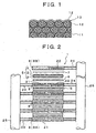
- FIG. 1 is an explanatory diagram schematically illustrating the internal structure of an electrode involved in the present invention.
- the electrode of the present example is provided with a structure in which grains 12 are adhered to a skeleton 11 made of a porous sintered compact having a three dimensional network structure.
- the skeleton 11 having a three dimensional network structure has large pores 13 (namely the network structure pores) formed by the gas bubble generation caused by liquid evaporation, grains 12 are adhered onto the outside surface of the skeleton 11, and the grains 12 are baked in the interior of the large pores 13 in such a condition that the grains are filled in the interior of the large pores.
- the interior of the sintered compact is formed of a collection of the small pores between the grains constituting the skeleton 11; however, in the illustrated example, drawing is simplified and the portion concerned is depicted with dots.
- the outside surface of the skeleton 11 on which the grains 12 are adhered and the large pores 13 in the network structure filled with the grains 12 constitute the electrode surface. Consequently, as compared to the above-described technique of a prior application (see Japanese Patent Laid-Open No. 2000-200614), the surface area of the electrode is increased and hence the three-phase boundary length is drastically increased, so that a further improvement of the electrode properties can be expected. Additionally, the porosity of the skeleton of the electrode materials is extremely large, and accordingly, the effect for alleviating the thermal shock and thermal strain is significant, and the generation of the fracture of the electrode caused by the difference in thermal expansion coefficient between the skeleton and the electrolyte can be prevented.
- the skeleton 11 of the electrode offers the path for the oxide ions, communicatively connected to the solid electrolyte, so that the skeleton is required to have a certain level of oxide ion conductivity. Accordingly, as the material for the skeleton, there is used at least one selected from an oxide ion conducting material and a mixed oxide ion conducting material.
- the adhered grains 12 offer the path for the electrons necessary for exchanging the oxide ions on the three-phase boundary, so that the adhered grains are required to have a certain level of electronic conductivity.
- the adhered grains are formed of at least one selected from an electron conducting material and a mixed oxide ion conducting material.
- at least a part of the adhered grains are formed of an electron conducting material.
- the adhered grains are formed of either an electron conducting material or a mixture of an electron conducting material and a mixed oxide ion conducting material.
- the materials suitable for the skeleton 11 to be cited in the first place are the oxide ion conducting materials which have hitherto been used as the solid electrolytes for use in the solid oxide fuel cell. More specifically, yttria stabilized zirconia (YSZ) having a fluorite crystal structure is one of the typical such materials; however, other oxide ion conducting materials, known to be usable as the solid electrolytes for use in the fuel cell, can also be used.
- YSZ yttria stabilized zirconia
- oxide ion conducting material having a higher conductivity than YSZ there can be cited lanthanum gallate based materials having the perovskite crystal structure and the compositions represented by the following formula (1). These materials have suitable properties for solid electrolyte of solid oxide fuel cells, such as a high conductivity even at low temperatures, which enables construction of solid oxide fuel cells operable at a temperature lower than about 1000°C, a typical operating temperature employed heretofore. These materials are also extremely suitable as a material for the skeleton of the electrodes in the present invention. Ln 1-x A x Ga 1-y-z Bl y B2 z O 3 where
- a mixed oxide ion conducting material as an appropriate material, there can be cited a lanthanum gallate based material having the perovskite crystal structure, represented by the above formula (1) in which Ln, A, B1, B2 and x are the same as described above, and y and z are as follows:
- a lanthanum gallate based material having a composition represented by the above described formula (1) becomes an oxide ion conductor for the z value of 0.15 or less because the ion transport number is increased, but becomes an mixed oxide ion conductor for the z value exceeding 0.15 because the ion transport number is decreased.
- Examples of the metal represented by A' include Nd, Pr, Sm, Ce, Eu and Gd and the like; among these, Nd is particularly preferable.
- a material represented by the above described formula (2) can display a further higher conductivity than a material represented by formula (1).
- the skeleton is made of the above described mixed oxide ion conductor, because the overall conductivity is degraded in the reducing atmosphere to which the fuel electrode is exposed.
- the electrode is the air electrode (cathode)
- the material of the skeleton for the air electrode may be an oxide ion conductor, a mixed oxide ion conductor, or a mixture of both.
- the grains 12 adhered onto the outside surface of the skeleton 11 having the three dimensional network structure and the grains 12 filled in the pores 13 are constituted with an electron conducting material and/or a mixed oxide ion conducting material. These grains 12 can be constituted with the materials which have hitherto been used for the fuel electrode or the air electrode.
- Preferable is a mixture of one metal (preferably Ni), selected from Ni and Co, and Ce 1-m C m O 2 .
- the material for the adhered grains in the air electrode includes an electron conducting material or at least one material selected from the materials based on LaMnO 3 , LaCoO 3 , SmCoO 3 and the PrCoO 3 which are mixed oxide ion conducting materials.
- the LaMnO 3 based material includes a material in which La or Mn is partially replaced with other metals, and this is also the case for the other materials.
- a hitherto known material in which La is partially replaced with Sr and/or Ca can be used.
- the electrode of a solid oxide fuel cell is used in the form in which the electrode is integrated with the solid electrolyte layer.
- the electrode involved in the present invention which is formed by adhering the grains made of an electrode material to a porous sintered compact having a three dimensional network structure can be integrated with the electrolyte material by the thermocompression bonding before sintering or by the thermal spray of the electrolyte material to the sintered electrode.
- the skeleton of the electrode may be made of a material the same or the same in type as the material of the solid electrolyte layer. Materials of the same type intends to mean and represent materials which are the same in main component and crystal structure.
- the skeleton of the electrode can be constituted with the YSZ.
- the solid electrolyte is made of an oxide ion conductor represented by the above described formula (1) (namely, the z value is 0.15 or less)
- the skeleton of the electrode can be constituted with the same oxide ion conductor or a material represented by the above described formula (1) with the z value larger than 0.15 which is the same type of mixed oxide ion conductor.
- the compounds represented by the above described formula (2) can be used satisfactorily as the skeleton of the electrode materials because the compounds are of the same type in view of the fact that the compounds are among the rare earth gallates having the perovskite structure.
- the skeleton of the electrode is a three dimensional network structure having a large surface area, and this structure displays an effect for alleviating the thermal shock and the thermal strain; accordingly, even if the electrolyte and the skeleton of the electrode are different in the material type, the fracture caused by the difference in thermal expansion coefficient between the electrolyte and the skeleton hardly occurs.
- reference numeral 1 designates a fuel cell stack, which has a structure in which an electrochemically active cell 5 in which a fuel electrode layer 3 and an air electrode layer 4 are arranged respectively on both surfaces of a solid electrolyte layer 2, a fuel electrode current collector 6 arranged outside the fuel electrode layer 3, an air electrode current collector 7 arranged outside the air electrode layer 4, and the separators 8 arranged respectively outside the current collectors 6 and 7 are laminated in this order.
- a manifold 25 for fuel for supplying fuel gas through connecting pipes 23 to fuel paths 21 in the respective separators 8 and a manifold 26 for oxidant for supplying oxidant gas through connecting pipes 24 to oxidant paths 22 in the respective separators 8 are arranged so as to be extended along the stacking direction with respect to the electrochemically active cell 5.
- FIGS. 3 to 5 illustrate different examples of the internal structures of the electrochemically active cell 5 portion of the solid oxide cell shown in FIG. 2.
- reference numeral 4 denotes an air electrode
- reference numeral 2 denotes a solid electrolyte layer
- reference numeral 3 denotes a fuel electrode.
- FIG. 3 shows an example in which the electrode of the present invention is used as the fuel electrode 3
- FIG. 4 shows an example in which the electrode of the present invention is used as the air electrode 4
- FIG. 5 shows an example in which the electrode of the present invention is applied to the fuel electrode 3 and the air electrode 4.
- the electrode properties are drastically improved, and a solid oxide fuel cell can be actualized in which the thermal shock and the thermal strain are markedly reduced.
- the electrode of a solid oxide fuel cell involved in the present invention has a configuration in which grains made of an electrode material are adhered to the surface of a porous sintered compact (skeleton) having a three dimensional network structure with a large specific surface area, and the grains made of the electrode material are filled inside the voids of the porous sintered compact and baked inside the voids; accordingly, the three-phase boundary length is drastically increased, and hence the electrode properties are markedly improved.
- porous skeleton of the electrode has an extremely large specific surface area, and hence there acts an effect for alleviating the thermal shock and the thermal strain, so that generation of the breakdown of the electrode caused by the difference in thermal expansion coefficient between the skeleton and the electrolyte can be prevented.
- the porous skeleton of the electrode can be formed using the same material as that for the electrolyte, and hence the difference in thermal expansion coefficient between the skeleton and the electrolyte vanishes, so that the generation of the thermal strain itself can be eliminated.
Landscapes
- Chemical & Material Sciences (AREA)
- Engineering & Computer Science (AREA)
- Chemical Kinetics & Catalysis (AREA)
- Electrochemistry (AREA)
- General Chemical & Material Sciences (AREA)
- Materials Engineering (AREA)
- Physics & Mathematics (AREA)
- Thermal Sciences (AREA)
- Manufacturing & Machinery (AREA)
- Ceramic Engineering (AREA)
- Inert Electrodes (AREA)
- Fuel Cell (AREA)
Applications Claiming Priority (3)
| Application Number | Priority Date | Filing Date | Title |
|---|---|---|---|
| JP2002057062 | 2002-03-04 | ||
| JP2002057062A JP2003257437A (ja) | 2002-03-04 | 2002-03-04 | 固体酸化物形燃料電池の電極および固体酸化物形燃料電池 |
| PCT/JP2003/002201 WO2003075378A1 (en) | 2002-03-04 | 2003-02-27 | Electrode for solid oxide type fuel cell and solid oxide type fuel cell |
Publications (2)
| Publication Number | Publication Date |
|---|---|
| EP1482584A1 true EP1482584A1 (de) | 2004-12-01 |
| EP1482584A4 EP1482584A4 (de) | 2007-10-10 |
Family
ID=27784655
Family Applications (1)
| Application Number | Title | Priority Date | Filing Date |
|---|---|---|---|
| EP03707135A Withdrawn EP1482584A4 (de) | 2002-03-04 | 2003-02-27 | Elektrode für eine brennstoffzelle des festoxidtyps und brennstoffzelle des festoxidtyps |
Country Status (5)
| Country | Link |
|---|---|
| US (1) | US20050089749A1 (de) |
| EP (1) | EP1482584A4 (de) |
| JP (1) | JP2003257437A (de) |
| AU (1) | AU2003211771A1 (de) |
| WO (1) | WO2003075378A1 (de) |
Cited By (4)
| Publication number | Priority date | Publication date | Assignee | Title |
|---|---|---|---|---|
| EP2104165A1 (de) * | 2008-03-18 | 2009-09-23 | The Technical University of Denmark | Ausschliesslich aus Keramik bestehende Festoxidbrennstoffzelle |
| CN103936082A (zh) * | 2014-04-10 | 2014-07-23 | 东北大学 | 一种钴酸钐纳米粉体的合成方法 |
| US9496576B2 (en) | 2006-11-23 | 2016-11-15 | Technical University Of Denmark | Thin solid oxide cell |
| CN107055630A (zh) * | 2017-03-09 | 2017-08-18 | 南京工业大学 | 三维有序大孔结构的钙钛矿材料3DOM‑SmCoO3及其制备方法和应用 |
Families Citing this family (10)
| Publication number | Priority date | Publication date | Assignee | Title |
|---|---|---|---|---|
| JP4923407B2 (ja) * | 2004-01-16 | 2012-04-25 | 三菱マテリアル株式会社 | 固体酸化物形燃料電池の製造方法 |
| JP2006286221A (ja) * | 2005-03-31 | 2006-10-19 | Tokyo Electric Power Co Inc:The | 固体酸化物形燃料電池用電極及び固体酸化物形燃料電池 |
| JP2008538543A (ja) * | 2005-04-21 | 2008-10-30 | ザ、リージェンツ、オブ、ザ、ユニバーシティ、オブ、カリフォルニア | 前駆体物質溶浸およびコーティング方法 |
| JP4883954B2 (ja) * | 2005-07-27 | 2012-02-22 | 関西電力株式会社 | 固体酸化物形燃料電池及びその製造方法 |
| JP5127126B2 (ja) * | 2005-09-01 | 2013-01-23 | 国立大学法人東京工業大学 | 燃料電池用の電極およびこれを用いた固体電解質型燃料電池 |
| US8278013B2 (en) * | 2007-05-10 | 2012-10-02 | Alan Devoe | Fuel cell device and system |
| JP2009295497A (ja) * | 2008-06-06 | 2009-12-17 | Kansai Electric Power Co Inc:The | 複合基板、複合基板の製造方法、固体酸化物形燃料電池セル、固体酸化物形燃料電池および固体酸化物形燃料電池の製造方法 |
| JP5365124B2 (ja) * | 2008-09-30 | 2013-12-11 | 大日本印刷株式会社 | 固体酸化物形燃料電池 |
| JP4995327B1 (ja) * | 2010-03-25 | 2012-08-08 | 日本碍子株式会社 | 電極材料、それを含む燃料電池セル、及びその製造方法 |
| JP2022518344A (ja) * | 2018-12-12 | 2022-03-15 | フイリツプス66カンパニー | 固体酸化物形燃料電池用のカソード |
Family Cites Families (7)
| Publication number | Priority date | Publication date | Assignee | Title |
|---|---|---|---|---|
| JPH0722056A (ja) * | 1993-07-02 | 1995-01-24 | Fuji Electric Co Ltd | 固体電解質型燃料電池の製造方法 |
| JP3323029B2 (ja) * | 1995-03-31 | 2002-09-09 | 京セラ株式会社 | 燃料電池セル |
| US5670270A (en) * | 1995-11-16 | 1997-09-23 | The Dow Chemical Company | Electrode structure for solid state electrochemical devices |
| DE19839202B4 (de) * | 1997-08-29 | 2009-09-10 | Mitsubishi Materials Corp. | Leitfähige Substanz aus Mischoxidionen und deren Verwendung |
| US6844098B1 (en) * | 1997-08-29 | 2005-01-18 | Mitsubishi Materials Corporation | Oxide-ion conductor and use thereof |
| JP3230156B2 (ja) * | 1999-01-06 | 2001-11-19 | 三菱マテリアル株式会社 | 固体酸化物型燃料電池の電極とその製造方法 |
| JP4517466B2 (ja) * | 2000-06-28 | 2010-08-04 | 三菱マテリアル株式会社 | 固体酸化物型燃料電池 |
-
2002
- 2002-03-04 JP JP2002057062A patent/JP2003257437A/ja active Pending
-
2003
- 2003-02-27 US US10/506,530 patent/US20050089749A1/en not_active Abandoned
- 2003-02-27 EP EP03707135A patent/EP1482584A4/de not_active Withdrawn
- 2003-02-27 WO PCT/JP2003/002201 patent/WO2003075378A1/ja not_active Ceased
- 2003-02-27 AU AU2003211771A patent/AU2003211771A1/en not_active Abandoned
Cited By (8)
| Publication number | Priority date | Publication date | Assignee | Title |
|---|---|---|---|---|
| US9496576B2 (en) | 2006-11-23 | 2016-11-15 | Technical University Of Denmark | Thin solid oxide cell |
| EP2104165A1 (de) * | 2008-03-18 | 2009-09-23 | The Technical University of Denmark | Ausschliesslich aus Keramik bestehende Festoxidbrennstoffzelle |
| WO2009115319A1 (en) * | 2008-03-18 | 2009-09-24 | Technical University Of Denmark | An all ceramics solid oxide fuel cell |
| US8741425B2 (en) | 2008-03-18 | 2014-06-03 | Technical University Of Denmark | All ceramics solid oxide fuel cell |
| CN103936082A (zh) * | 2014-04-10 | 2014-07-23 | 东北大学 | 一种钴酸钐纳米粉体的合成方法 |
| CN103936082B (zh) * | 2014-04-10 | 2015-11-11 | 东北大学 | 一种钴酸钐纳米粉体的合成方法 |
| CN107055630A (zh) * | 2017-03-09 | 2017-08-18 | 南京工业大学 | 三维有序大孔结构的钙钛矿材料3DOM‑SmCoO3及其制备方法和应用 |
| CN107055630B (zh) * | 2017-03-09 | 2019-08-09 | 南京工业大学 | 三维有序大孔结构的钙钛矿材料3DOM-SmCoO3及其制备方法和应用 |
Also Published As
| Publication number | Publication date |
|---|---|
| WO2003075378A1 (en) | 2003-09-12 |
| AU2003211771A1 (en) | 2003-09-16 |
| EP1482584A4 (de) | 2007-10-10 |
| JP2003257437A (ja) | 2003-09-12 |
| US20050089749A1 (en) | 2005-04-28 |
Similar Documents
| Publication | Publication Date | Title |
|---|---|---|
| JP5208518B2 (ja) | 可逆式固体酸化物型燃料電池を製造する方法 | |
| EP2529442B1 (de) | Phasenstabile dotierte zirkonium-elektrolytzusammensetzungen mit geringer zersetzung | |
| JP4981239B2 (ja) | 固体酸化物燃料電池の高性能陰極 | |
| US7601447B2 (en) | Electrolyte-electrode assembly comprising an isotropic layer | |
| US20130280634A1 (en) | Unit Cell of Metal-Supported Solid Oxide Fuel Cell, Preparation Method Thereof, and Solid Oxide Fuel Cell Stack Using the Unit Cell | |
| US20080254336A1 (en) | Composite anode showing low performance loss with time | |
| US20070037031A1 (en) | Cermet and ceramic interconnects for a solid oxide fuel cell | |
| WO2002035628A1 (en) | Fuel cells | |
| US10446855B2 (en) | Fuel cell system including multilayer interconnect | |
| EP1482584A1 (de) | Elektrode für eine brennstoffzelle des festoxidtyps und brennstoffzelle des festoxidtyps | |
| JP5188069B2 (ja) | 燃料電池セルおよびセルスタックならびに燃料電池 | |
| JP2016157693A (ja) | 固体酸化物形燃料電池単セル及び固体酸化物形燃料電池スタック | |
| JP2006073230A (ja) | 燃料電池セル | |
| JP5127438B2 (ja) | 電解質・電極接合体 | |
| US7297436B2 (en) | Fuel cell | |
| JP4390530B2 (ja) | 電解質・電極接合体及びその製造方法 | |
| KR102564764B1 (ko) | 전기 화학 장치, 에너지 시스템, 및 고체 산화물형 연료 전지 | |
| CN100573979C (zh) | 燃料电池用阴极及其制造方法 | |
| JP4828104B2 (ja) | 燃料電池セル | |
| US20260088309A1 (en) | Electrochemical cell | |
| US20260094846A1 (en) | Electrode and electrochemical cell | |
| DK2669984T3 (en) | Layered anode system for electrochemical applications and processes for their preparation | |
| CN111244498A (zh) | 燃料电池和燃料电池堆 | |
| KR101669469B1 (ko) | 연료전지용 하이브리드형 단위전지 및 이를 포함하는 연료전지 스택 | |
| US20170346102A1 (en) | Fuel cell system including dense oxygen barrier layer |
Legal Events
| Date | Code | Title | Description |
|---|---|---|---|
| PUAI | Public reference made under article 153(3) epc to a published international application that has entered the european phase |
Free format text: ORIGINAL CODE: 0009012 |
|
| 17P | Request for examination filed |
Effective date: 20040902 |
|
| AK | Designated contracting states |
Kind code of ref document: A1 Designated state(s): AT BE BG CH CY CZ DE DK EE ES FI FR GB GR HU IE IT LI LU MC NL PT SE SI SK TR |
|
| AX | Request for extension of the european patent |
Extension state: AL LT LV MK RO |
|
| RIN1 | Information on inventor provided before grant (corrected) |
Inventor name: SASAKI, T.,THE KANSAI ELECTRIC POWER CO., INC. Inventor name: YOSHIDA, H.,THE KANSAI ELECTRIC POWER CO., INC. Inventor name: INAGAKI, TORU,THE KANSAI ELECTRIC POWER CO., INC Inventor name: HOSOI, KEI,CENTRAL RES. INST. NAKA RES. CTR. Inventor name: ADACHI, K.,CENTRAL RES. INST. NAKA RES. CTR. Inventor name: HOSHINO, KOJI,CENTRAL RES. INST. NAKARES. CTR. Inventor name: KOMADA, N.,CENTRAL RES. INST. NAKA RES. CTR |
|
| A4 | Supplementary search report drawn up and despatched |
Effective date: 20070911 |
|
| 17Q | First examination report despatched |
Effective date: 20080529 |
|
| STAA | Information on the status of an ep patent application or granted ep patent |
Free format text: STATUS: THE APPLICATION IS DEEMED TO BE WITHDRAWN |
|
| 18D | Application deemed to be withdrawn |
Effective date: 20100619 |