EP1482684A2 - Vorrichtung und Verfahren zur Reduzierung der Übertragungsverzögerung in einem Datennetz - Google Patents
Vorrichtung und Verfahren zur Reduzierung der Übertragungsverzögerung in einem Datennetz Download PDFInfo
- Publication number
- EP1482684A2 EP1482684A2 EP04012267A EP04012267A EP1482684A2 EP 1482684 A2 EP1482684 A2 EP 1482684A2 EP 04012267 A EP04012267 A EP 04012267A EP 04012267 A EP04012267 A EP 04012267A EP 1482684 A2 EP1482684 A2 EP 1482684A2
- Authority
- EP
- European Patent Office
- Prior art keywords
- packet data
- transmission
- memory
- stored
- memory area
- Prior art date
- Legal status (The legal status is an assumption and is not a legal conclusion. Google has not performed a legal analysis and makes no representation as to the accuracy of the status listed.)
- Granted
Links
Images



Classifications
-
- H—ELECTRICITY
- H04—ELECTRIC COMMUNICATION TECHNIQUE
- H04L—TRANSMISSION OF DIGITAL INFORMATION, e.g. TELEGRAPHIC COMMUNICATION
- H04L69/00—Network arrangements, protocols or services independent of the application payload and not provided for in the other groups of this subclass
- H04L69/04—Protocols for data compression, e.g. ROHC
-
- H—ELECTRICITY
- H04—ELECTRIC COMMUNICATION TECHNIQUE
- H04L—TRANSMISSION OF DIGITAL INFORMATION, e.g. TELEGRAPHIC COMMUNICATION
- H04L49/00—Packet switching elements
- H04L49/90—Buffering arrangements
-
- H—ELECTRICITY
- H04—ELECTRIC COMMUNICATION TECHNIQUE
- H04L—TRANSMISSION OF DIGITAL INFORMATION, e.g. TELEGRAPHIC COMMUNICATION
- H04L49/00—Packet switching elements
- H04L49/90—Buffering arrangements
- H04L49/9084—Reactions to storage capacity overflow
- H04L49/9089—Reactions to storage capacity overflow replacing packets in a storage arrangement, e.g. pushout
- H04L49/9094—Arrangements for simultaneous transmit and receive, e.g. simultaneous reading/writing from/to the storage element
Definitions
- the present invention relates generally to an apparatus and method for preventing data transmission delay, and in particular, to an apparatus and method for preventing data transmission delay using a combining technique in a high-speed router and a switch.
- the typical techniques include an overhead compression technique and a packet data combining technique.
- a protocol such as TCP/IP Transmission Control Protocol/Internet Protocol
- the protocol adds a header of 40 bytes or more to transmission data
- a transmission overhead of a predetermined amount occurs regardless of an amount of the actual transmission data. This processdeteriorates system performance.
- the overhead compression technique compresses headers by 4 to 6 bytes, and adds the compressed headers to the transmission data. This technique can reduce the total number of transmissions, thereby contributing to an increase in transmission throughput and a decrease in a round trip time.
- the packet data combining technique combines two or more data packets and then transmits the combined data in one overhead packet in order to reduce the overall overhead of each layer. This also decreases a time delay occurring due to a protocol characteristic in which a header and a tail are added to each transmission data. Such an overhead is larger in size in a wireless environment than in a wired environment.
- the combining technique performs better in a medium access control (MAC) protocol, and is generally used when transmitting data in a high-speed router or a switch.
- MAC medium access control
- FIG. 1 is a block diagram illustrating a structure of a conventional transmission module for preventing transmission delay of packet data.
- the data transmission module is comprised of a transmission manager 10 for controlling management of transmission data and preprocessing for the protocol header, and a transmission protocol engine 20 for transmitting actual packet data according to a transmission protocol.
- the transmission manager 10 includes a transmission queue 11 for storing data and a frame processor 12 for combining data packets stored in the transmission queue 11, for data management. Further, the transmission manager 10 includes a transmission wait timer (Tx_Wait_Timer) for delaying packet data stored in the transmission queue 11 in order to combine the packet data with subsequent packet data received.
- Tx_Wait_Timer transmission wait timer
- the transmission protocol engine 20 includes a transmission buffer 21 for storing packet data received from the transmission queue 11 to transmit the stored packet data at a transmission time, and a transmission controller 22 for controlling transmission of the packet data.
- a transmission buffer 21 for storing packet data received from the transmission queue 11 to transmit the stored packet data at a transmission time
- a transmission controller 22 for controlling transmission of the packet data.
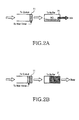
- the transmission buffer 21 Although data combined by the transmission buffer 21 is stored, if the stored combined data cannot be transmitted because of a busy state of a channel, data will accumulate in the transmission queue 11. In order to increase transmission throughput, it is effective to combine data in the transmission buffer 21 with data in the transmission queue 11. However, the conventional combining technique can combine only the data in the transmission queue 11, since the transmission manager 10 cannot consider a situation of the transmission buffer 21.
- an object of the present invention to provide an apparatus and method for preventing transmission delay using a descriptor combining technique capable of recombining.
- the apparatus comprises a first memory having a first memory area for storing packet data to be transmitted and a second memory area for temporarily storing the packet data and for combining the packet data with subsequent packet data; a second memory for receiving and storing a copy of the packet data temporarily stored in the second memory area, and transmitting the packet data to a destination according to a link state; and a frame processor for storing a copy of the packet data stored in the second memory area in the second memory according to a state of the second memory, deleting packet data stored in the second memory area when the copy of the packet data stored in the second memory is transmitted, determining whether packet data combining is possible according to a state of the second memory area, and, if the packet data combining is possible, combining packet data stored in the first memory area with the packet data stored in the second memory area, and storing the combined packet data in the second memory.
- a method for reducing transmission delay occurring when transmitting packet data to a destination in a transmission module including a first memory having a first memory area for storing the packet data to be transmitted and a second memory area for backing up the first memory area, a second memory connected to a transmission link, and a frame processor.
- the method comprises the steps of: storing a copy of the packet data stored in the second memory area according to a state of the second memory; deleting the packet data stored in the second memory area if the copy of the packet data stored in the second memory is transmitted; determining whether packet data combining is possible according to a state of the second memory area; and if the packet data combining is possible, combining the packet data stored in the first memory area with the packet data stored in the second memory area and storing the combined packet data in the second memory.
- a backup queue for temporarily storing packet data transmitted to a transmission buffer without being combined in a transmission queue is added to a transmission manager.
- the backup queue is used for recombining. Therefore, a transmission wait timer is not required.
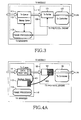
- FIG. 3 is a block diagram illustrating a structure of a transmission module for data combining according to an embodiment of the present invention.
- the data transmission module is comprised of a transmission manager 110 for controlling management of transmission data and preprocessing a protocol header, and a transmission protocol engine 120 for transmitting actual packet data according to a transmission protocol.
- the transmission manager 110 includes a transmission queue 111 for storing data and a frame processor 113 for combining data packets stored in the transmission queue 111, for data management.
- the transmission manager 110 includes a backup queue 112 for temporarily storing packet data to be transmitted to the transmission protocol engine 120.
- the backup queue 112 is realized using a separate list linked to the transmission queue 111 rather than a separate new memory. That is, the backup queue 112 manages data using only a memory link without movement of a separate memory between the backup queue 112 and the transmission queue 111.
- the transmission protocol engine 120 includes a transmission buffer 121 for storing packet data received from the transmission queue 111 to transmit the stored packet data at a transmission time, and a transmission controller 122 for controlling transmission of the packet data.
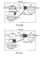
- FIG. 4A is a block diagram illustrating an operation of linking transmission data to a backup queue and then delivering the transmission data to a transmission buffer in an idle state according to an embodiment of the present invention.
- the frame processor 113 compares data stored in the transmission queue 111 with data stored in the transmission buffer 121 to determine whether they can be combined. At this moment, if there is no data previously stored in the transmission queue 111, i.e., if the transmission queue 111 is null (or empty), the frame processor 113 temporarily stores the received packet data in the backup queue 112 in step 401 since there is no data to be combined, and immediately transmits the same packet data to the transmission buffer 121 in step 402.
- the transmission controller 122 of the transmission protocol engine 120 determines whether a link connected to the transmission buffer 121 is busy. At this moment, if the link is in an idle state, the transmission controller 122 immediately transmits the packet data stored in the transmission buffer 121 to a destination. Accordingly, the frame processor 113, which was monitoring the transmission buffer 121, deletes the packet data stored in the backup queue 112.
- the transmission module is in a busy state of a transmission link, that is, data stored in the transmission buffer 121 is awaiting transmission to a corresponding destination. Accordingly, if new packet data arrives at the transmission queue 111 while previously arrived packet data is stored in the backup queue 112 and the transmission buffer 121, the frame processor 113 determines whether packet data stored in the transmission queue 111 can be combined with packet data stored in the backup queue 112. That is, the frame processor 113 determines whether there is packet data in the backup queue 112.
- the frame processor 113 deletes the packet data in the transmission buffer 121 on a flush basis in step 501. Thereafter, in step 502, the frame processor 113 combines the currently received packet data in the transmission queue 111 with the previous packet data temporarily stored in the backup queue 112, and stores the combined packet data back in the backup queue 112.
- the frame processor 113 transmits the combined packet data to the transmission buffer 121.
- the transmission buffer 121 then stores the combined packet data, and transmits the combined packet data to a destination if a connected link has a good condition at a transmission time.
- the link is continuously in a busy state, it means that the combined packet data stored in the transmission buffer 121 is continuously awaiting transmission at the transmission time.
- the frame processor 113 recombines the newly received packet data with the combined packet data. The recombining operation will be described in detail with reference to the accompanying drawings.
- FIG. 4D is a block diagram illustrating an operation of recombining combined packet data with new packet data according to an embodiment of the present invention.
- the frame processor 113 deletes packet data stored in the transmission buffer 121 on a flush basis in step 701 in order to recombine the received packet data in the transmission queue 111 with packet data stored in the backup queue 112. Thereafter, in step 702, the frame processor 113 recombines the received packet data in the transmission queue 111 with the combined packet data in the backup queue 112, and transmits the recombined packet data to the transmission buffer 121.
- the transmission controller 122 then continuously monitors a link condition and transmits the packet data stored in the transmission buffer 121 to a destination.
- FIG. 5A is a block diagram illustrating states of a transmission buffer and a backup queue in a transmission module when a MAC protocol is applied in an idle state according to an embodiment of the present invention.
- the frame processor 113 determines whether combining is possible. That is, the frame processor 113 determines whether there is any packet data in the backup queue 112. As a result of the determination, if the combining is not possible, the frame processor 113 transmits packet data F1 in the transmission queue 111to the transmission buffer 121. Further, the frame processor 113 temporarily stores the packet data F1 in the backup queue 112.
- a first area of the transmission buffer 121 is represented by "F1" since the received packet data is stored therein, while the other areas are shown by “Null” since there is no packet data stored therein.
- a first area of a descriptor 123 having information on the packet data in the transmission buffer 121 is represented by "P_F1" as it is a first area of the transmission buffer 121, while the other areas are represented by "Null.”
- FIGs. 5B to 5F are block diagrams illustrating states of the transmission buffer and the backup queue of the transmission module when a MAC protocol is applied in a busy state according to an embodiment of the present invention.
- the backup queue 112 stores a copy of the received packet data F2.
- previous packet data F1 has been stored in the transmission buffer 121 and has not yet been transmitted to a corresponding destination.
- the frame processor 113 can combine the packet data F1 with the packet data F2.
- the transmission buffer 121 and the descriptor 123 are identical in states to the transmission buffer 121 and the descriptor 123 of FIG. 5A, and, in this state, the packet data F1 has not been transmitted yet.
- the frame processor 113 deletes the packet data F1 stored in the transmission buffer 121, so all areas are null.
- all areas of the descriptor 123 are represented by "Null.”
- the backup queue 112 stores a copy of the combined (or aggregated) packet data Agg1
- the transmission buffer 121 stores the combined packet data Agg1 in its second area.
- the other areas of the transmission buffer 121 are all null.
- a second area of the descriptor 123 is represented by "P_A1," while the other areas are shown by "Null.”
- the frame processor 113 deletes packet data Agg1 stored in the transmission buffer 121, so all areas of the transmission buffer 121 are null. In addition, all areas of the descriptor 123 are represented by "Null.”
- the fame processor 113 combines the new packet data F3 with the previously combined packet data Agg1
- the backup queue 112 stores a copy of recombined packet data Agg2
- the transmission buffer 121 stores the recombined packet data Agg2 in its third area.
- a third area of the descriptor 123 is represented by "P_A2,” while the other areas are represented by "Null.”
- FIG. 6 is a flowchart illustrating an operation of combining packet data in a transmission module according to an embodiment of the present invention.
- the frame processor 113 determines whether data is received at the transmission queue 111. As a result of the determination, if data is received at the transmission queue 111, the frame processor 113 determines in step 1020 whether the received packet data can be combined, i.e., whether a copy of the packet data is stored in the backup queue 112. If the combining is not possible, i.e., there is not stored a copy of the packet data, the frame processor 113 transmits the received packet data intact to the transmission buffer 121 in step 1025 and stores temporarily the packet data in the backup queue 112, and then proceeds to step 1060.
- the frame processor 113 copies packet data stored in the transmission buffer 121 in step 1030, transmits a copy of the packet data to the backup queue 112 and deletes the packet data stored in the transmission buffer. Thereafter, in step 1040, the frame processor 113 combines previous packet data stored in the backup queue 112 with the received packet data and at the same time, stores the combined packet data in the backup queue 112. Thereafter, in step 1050, the frame processor 113 transmits the combined packet data to the transmission buffer 121. Then, the transmission controller 122 of the transmission protocol engine 120 determines whether a link connected to the transmission buffer 121 is busy.
- the transmission controller 122 immediately transmits the packet data stored in the transmission buffer 121 to a destination. Accordingly, the frame processor 113, which monitors the transmission buffer 121, determines whether the packet data arrives at the destination in step 1060. If the packet data arrives at the destination, the frame processor 113 returns to step 1010 where it determines whether new packet data is received at the transmission queue 111. However, if the packet data is not transmitted to the destination, the frame processor 113, which was monitoring the transmission buffer 121 in step 1070, deletes the packet data stored in the backup queue 112 and then returns to step 1010.
- the packet data combining technique can also be applied together with a technique for compressing a header of packet data when combining the packet data stored in the transmission queue.
- the invention temporarily stores packet data to be transmitted to a transmission buffer, determines a state of the transmission buffer, and immediately transmits the packet data when the transmission buffer is in an idle state, and combines the newly received packet data with previously received packet data before transmission when the transmission buffer is in a busy state, thereby preventing transmission delay of packet data and increasing transmission throughput.
- the invention recombines the combined packet data, thereby more effectively preventing transmission delay and increasing transmission throughput.
- a backup queue can utilize an existing transmission queue by adding an independent link, additional memory capacity is not required and movement of memory data is minimized, thereby contributing to minimization of performance degradation.
Landscapes
- Engineering & Computer Science (AREA)
- Computer Networks & Wireless Communication (AREA)
- Signal Processing (AREA)
- Computer Security & Cryptography (AREA)
- Data Exchanges In Wide-Area Networks (AREA)
- Communication Control (AREA)
Applications Claiming Priority (2)
| Application Number | Priority Date | Filing Date | Title |
|---|---|---|---|
| KR10-2003-0033460A KR100506253B1 (ko) | 2003-05-26 | 2003-05-26 | 데이터 통신 시스템에서 전송 지연을 최소화하기 위한장치 및 방법 |
| KR2003033460 | 2003-05-26 |
Publications (3)
| Publication Number | Publication Date |
|---|---|
| EP1482684A2 true EP1482684A2 (de) | 2004-12-01 |
| EP1482684A3 EP1482684A3 (de) | 2005-11-23 |
| EP1482684B1 EP1482684B1 (de) | 2011-08-10 |
Family
ID=33129038
Family Applications (1)
| Application Number | Title | Priority Date | Filing Date |
|---|---|---|---|
| EP04012267A Expired - Lifetime EP1482684B1 (de) | 2003-05-26 | 2004-05-24 | Vorrichtung und Verfahren zur Reduzierung der Übertragungsverzögerung in einem Datennetz |
Country Status (3)
| Country | Link |
|---|---|
| US (1) | US7558279B2 (de) |
| EP (1) | EP1482684B1 (de) |
| KR (1) | KR100506253B1 (de) |
Families Citing this family (25)
| Publication number | Priority date | Publication date | Assignee | Title |
|---|---|---|---|---|
| KR100633102B1 (ko) * | 2004-01-27 | 2006-10-12 | 삼성전자주식회사 | 단일세션을 이용하는 패킷을 병합전송하는 무선 네트워크단말장치 및 그 전송방법 |
| JP2006155817A (ja) * | 2004-11-30 | 2006-06-15 | Toshiba Corp | 信号出力装置及び信号出力方法 |
| US7738582B2 (en) * | 2005-03-02 | 2010-06-15 | Rohde & Schwarz Gmbh & Co. Kg | Apparatus, systems and methods for producing coherent symbols in a single frequency network |
| US7532857B2 (en) * | 2005-03-02 | 2009-05-12 | Rohde & Schwarz Gmbh & Co. Kg | Apparatus, systems and methods for providing time diversity for mobile broadcast services |
| US7822139B2 (en) * | 2005-03-02 | 2010-10-26 | Rohde & Schwarz Gmbh & Co. Kg | Apparatus, systems, methods and computer products for providing a virtual enhanced training sequence |
| US20060245516A1 (en) * | 2005-03-02 | 2006-11-02 | Rohde & Schwarz, Inc. | Apparatus, systems and methods for providing in-band atsc vestigial sideband signaling or out-of-band signaling |
| WO2006094054A2 (en) | 2005-03-02 | 2006-09-08 | Rohde & Schwarz Gmbh & Co.Kg | Apparatus, systems and methods for providing enhancements to atsc networks using synchronous vestigial sideband (vsb) frame slicing |
| CA2611337C (en) * | 2005-06-07 | 2013-08-20 | Rohde & Schwarz Gmbh & Co. Kg | Apparatus, systems and methods for providing time diversity for mobile broadcast services |
| JP4372110B2 (ja) * | 2006-02-10 | 2009-11-25 | エヌイーシーコンピュータテクノ株式会社 | データ転送回路、それを利用したマルチプロセッサシステム、及びデータ転送方法 |
| MX2009007049A (es) * | 2007-02-01 | 2009-08-13 | Rohde & Schwarz | Sistemas, aparatos, metodos y productos de programa de computadora para proporcionar interoperabilidad atsc. |
| DE102008017290A1 (de) * | 2007-12-11 | 2009-06-18 | Rohde & Schwarz Gmbh & Co. Kg | Verfahren und Vorrichtung zur Bildung eines gemeinsamen Datenstroms insbesondere nach dem ATSC-Standard |
| DE102007059959B4 (de) * | 2007-12-12 | 2020-01-02 | Rohde & Schwarz Gmbh & Co. Kg | Verfahren und System zur Übertragung von Daten zwischen einer zentralen Rundfunkstation und mindestens einem Sender |
| US8355458B2 (en) * | 2008-06-25 | 2013-01-15 | Rohde & Schwarz Gmbh & Co. Kg | Apparatus, systems, methods and computer program products for producing a single frequency network for ATSC mobile / handheld services |
| DE102008056703A1 (de) * | 2008-07-04 | 2010-01-07 | Rohde & Schwarz Gmbh & Co. Kg | Verfahren und System zur Zeitsynchronisierung zwischen einer Zentrale und mehreren Sendern |
| DE102008059028B4 (de) * | 2008-10-02 | 2021-12-02 | Rohde & Schwarz GmbH & Co. Kommanditgesellschaft | Verfahren und Vorrichtung zur Erzeugung eines Transportdatenstroms mit Bilddaten |
| MX2011004645A (es) * | 2008-11-06 | 2011-05-30 | Rohde & Schwarz | Metodo y sistema para la asignacion sincronizada de paquetes de datos en un flujo de datos atsc. |
| WO2010074566A1 (en) | 2008-12-22 | 2010-07-01 | Nederlandse Organisatie Voor Toegepast-Natuurwetenschappelijk Onderzoek Tno | Method and apparatus for layerwise production of a 3d object |
| US8777602B2 (en) | 2008-12-22 | 2014-07-15 | Nederlandse Organisatie Voor Tobgepast-Natuurwetenschappelijk Onderzoek TNO | Method and apparatus for layerwise production of a 3D object |
| US8678805B2 (en) | 2008-12-22 | 2014-03-25 | Dsm Ip Assets Bv | System and method for layerwise production of a tangible object |
| US8982745B2 (en) * | 2009-03-21 | 2015-03-17 | Rohde & Schwarz Gmbh & Co. Kg | Method for improving the data rate of mobile/handheld data and the quality of channel estimation in an ATSC-M/H transport data stream |
| DE102009025219A1 (de) * | 2009-04-07 | 2010-10-14 | Rohde & Schwarz Gmbh & Co. Kg | Verfahren und Vorrichtung zur kontinuierlichen Anpassung von Kodierungsparametern an eine veränderliche Nutzdatenrate |
| DE102009057363B4 (de) | 2009-10-16 | 2013-04-18 | Rohde & Schwarz Gmbh & Co. Kg | Verfahren und Vorrichtung zur effizienten Übertragung von überregional und regional auszustrahlenden Programm-und Servicedaten |
| US8989021B2 (en) | 2011-01-20 | 2015-03-24 | Rohde & Schwarz Gmbh & Co. Kg | Universal broadband broadcasting |
| US20120226827A1 (en) * | 2011-03-02 | 2012-09-06 | Qualcomm Incorporated | Mechanism for Performing SDIO Aggregation and Conveying SDIO Device Status to the Host Software |
| US11416159B2 (en) * | 2019-04-29 | 2022-08-16 | EMC IP Holding Company LLC | Method and system for prioritizing critical data object storage during backup operations |
Family Cites Families (7)
| Publication number | Priority date | Publication date | Assignee | Title |
|---|---|---|---|---|
| US4998247A (en) * | 1988-06-10 | 1991-03-05 | Irvine Halliday David | Active star-configured local area network |
| US6721334B1 (en) * | 1999-02-18 | 2004-04-13 | 3Com Corporation | Method and apparatus for packet aggregation in packet-based network |
| US6400724B1 (en) * | 1999-07-16 | 2002-06-04 | Qualcomm Inc. | Method and apparatus for efficient data transmission in a voice-over-data communication system |
| US6826152B1 (en) | 2000-09-13 | 2004-11-30 | Harris Corporation | System and method of conserving bandwidth in the transmission of message packets |
| US6741554B2 (en) * | 2002-08-16 | 2004-05-25 | Motorola Inc. | Method and apparatus for reliably communicating information packets in a wireless communication network |
| US7185338B2 (en) * | 2002-10-15 | 2007-02-27 | Sun Microsystems, Inc. | Processor with speculative multithreading and hardware to support multithreading software |
| US7414989B2 (en) * | 2003-05-07 | 2008-08-19 | Motorola, Inc. | ACK/NACK determination reliability for a communication device |
-
2003
- 2003-05-26 KR KR10-2003-0033460A patent/KR100506253B1/ko not_active Expired - Fee Related
-
2004
- 2004-05-21 US US10/851,625 patent/US7558279B2/en not_active Expired - Fee Related
- 2004-05-24 EP EP04012267A patent/EP1482684B1/de not_active Expired - Lifetime
Also Published As
| Publication number | Publication date |
|---|---|
| EP1482684A3 (de) | 2005-11-23 |
| US7558279B2 (en) | 2009-07-07 |
| KR100506253B1 (ko) | 2005-08-10 |
| US20040240460A1 (en) | 2004-12-02 |
| EP1482684B1 (de) | 2011-08-10 |
| KR20040101746A (ko) | 2004-12-03 |
Similar Documents
| Publication | Publication Date | Title |
|---|---|---|
| US7558279B2 (en) | Apparatus and method for minimizing transmission delay in a data communication system | |
| JP3321043B2 (ja) | Tcpネットワーク内のデータ端末 | |
| US7355971B2 (en) | Determining packet size in networking | |
| US20090268747A1 (en) | Communication apparatus | |
| US20190044878A1 (en) | Technologies for managing tcp/ip packet delivery | |
| US20060203730A1 (en) | Method and system for reducing end station latency in response to network congestion | |
| JP2002539678A (ja) | データネットワーク内の多重受信確認管理システム | |
| JP2007527170A (ja) | 並列通信のためのシステムおよび方法 | |
| US7269752B2 (en) | Dynamically controlling power consumption within a network node | |
| US7583594B2 (en) | Adaptive transmit window control mechanism for packet transport in a universal port or multi-channel environment | |
| CN111131075A (zh) | 一种高并发数据包缓冲方法 | |
| EP1889421B1 (de) | Terminplanung für mehrstromquittierungen | |
| US7391785B2 (en) | Method for active queue management with asymmetric congestion control | |
| US9160664B1 (en) | Determining a network node whether a received packet fragment should be transmitted | |
| US20070291782A1 (en) | Acknowledgement filtering | |
| CN119011476B (zh) | 快速传递ecn拥塞信息的方法和系统 | |
| US6434116B1 (en) | Method and system for stabilized random early detection using connection sampling | |
| JPH11239163A (ja) | Lan間フロー制御方法及びスイッチ | |
| US8054847B2 (en) | Buffer management in a network device | |
| TWI831622B (zh) | 網路流壅塞管理裝置及其方法 | |
| US20230269183A1 (en) | Apparatus and method for managing network flow congestion | |
| CN117714432A (zh) | 基于工业app的音视频数据网络传输可靠性优化方法 | |
| CN115695311B (zh) | 一种RoCE v2网络环境流量控制方法、系统和存储介质 | |
| US20060067311A1 (en) | Method of processing packet data at a high speed | |
| KR100429503B1 (ko) | 데이터 패킷의 흐름제어 방법 |
Legal Events
| Date | Code | Title | Description |
|---|---|---|---|
| PUAI | Public reference made under article 153(3) epc to a published international application that has entered the european phase |
Free format text: ORIGINAL CODE: 0009012 |
|
| 17P | Request for examination filed |
Effective date: 20040524 |
|
| AK | Designated contracting states |
Kind code of ref document: A2 Designated state(s): AT BE BG CH CY CZ DE DK EE ES FI FR GB GR HU IE IT LI LU MC NL PL PT RO SE SI SK TR |
|
| AX | Request for extension of the european patent |
Extension state: AL HR LT LV MK |
|
| RAP1 | Party data changed (applicant data changed or rights of an application transferred) |
Owner name: SEOUL NATIONAL UNIVERSITY INDUSTRY FOUNDATION Owner name: SAMSUNG ELECTRONICS CO., LTD. |
|
| PUAL | Search report despatched |
Free format text: ORIGINAL CODE: 0009013 |
|
| AK | Designated contracting states |
Kind code of ref document: A3 Designated state(s): AT BE BG CH CY CZ DE DK EE ES FI FR GB GR HU IE IT LI LU MC NL PL PT RO SE SI SK TR |
|
| AX | Request for extension of the european patent |
Extension state: AL HR LT LV MK |
|
| RIC1 | Information provided on ipc code assigned before grant |
Ipc: 7H 04L 29/06 B Ipc: 7H 04L 12/56 A |
|
| AKX | Designation fees paid |
Designated state(s): DE FI FR GB IT SE |
|
| 17Q | First examination report despatched |
Effective date: 20060330 |
|
| GRAP | Despatch of communication of intention to grant a patent |
Free format text: ORIGINAL CODE: EPIDOSNIGR1 |
|
| GRAS | Grant fee paid |
Free format text: ORIGINAL CODE: EPIDOSNIGR3 |
|
| GRAA | (expected) grant |
Free format text: ORIGINAL CODE: 0009210 |
|
| RIN1 | Information on inventor provided before grant (corrected) |
Inventor name: JANG, KYUNG-HUN Inventor name: CHOI, SUNG-HYUN Inventor name: KIM, YOUNG-SOO Inventor name: HWANG, HYO-SUN |
|
| AK | Designated contracting states |
Kind code of ref document: B1 Designated state(s): DE FI FR GB IT SE |
|
| REG | Reference to a national code |
Ref country code: GB Ref legal event code: FG4D |
|
| REG | Reference to a national code |
Ref country code: DE Ref legal event code: R096 Ref document number: 602004033819 Country of ref document: DE Effective date: 20111013 |
|
| REG | Reference to a national code |
Ref country code: SE Ref legal event code: TRGR |
|
| PLBE | No opposition filed within time limit |
Free format text: ORIGINAL CODE: 0009261 |
|
| STAA | Information on the status of an ep patent application or granted ep patent |
Free format text: STATUS: NO OPPOSITION FILED WITHIN TIME LIMIT |
|
| 26N | No opposition filed |
Effective date: 20120511 |
|
| REG | Reference to a national code |
Ref country code: DE Ref legal event code: R097 Ref document number: 602004033819 Country of ref document: DE Effective date: 20120511 |
|
| PGFP | Annual fee paid to national office [announced via postgrant information from national office to epo] |
Ref country code: DE Payment date: 20130423 Year of fee payment: 10 Ref country code: SE Payment date: 20130423 Year of fee payment: 10 Ref country code: GB Payment date: 20130426 Year of fee payment: 10 |
|
| PGFP | Annual fee paid to national office [announced via postgrant information from national office to epo] |
Ref country code: FI Payment date: 20130423 Year of fee payment: 10 Ref country code: IT Payment date: 20130423 Year of fee payment: 10 Ref country code: FR Payment date: 20130515 Year of fee payment: 10 |
|
| REG | Reference to a national code |
Ref country code: DE Ref legal event code: R119 Ref document number: 602004033819 Country of ref document: DE |
|
| REG | Reference to a national code |
Ref country code: DE Ref legal event code: R079 Ref document number: 602004033819 Country of ref document: DE Free format text: PREVIOUS MAIN CLASS: H04L0012560000 Ipc: H04L0012841000 |
|
| GBPC | Gb: european patent ceased through non-payment of renewal fee |
Effective date: 20140524 |
|
| PG25 | Lapsed in a contracting state [announced via postgrant information from national office to epo] |
Ref country code: FI Free format text: LAPSE BECAUSE OF NON-PAYMENT OF DUE FEES Effective date: 20140524 Ref country code: SE Free format text: LAPSE BECAUSE OF NON-PAYMENT OF DUE FEES Effective date: 20140525 |
|
| REG | Reference to a national code |
Ref country code: SE Ref legal event code: EUG |
|
| REG | Reference to a national code |
Ref country code: DE Ref legal event code: R079 Ref document number: 602004033819 Country of ref document: DE Free format text: PREVIOUS MAIN CLASS: H04L0012560000 Ipc: H04L0012841000 Effective date: 20150116 Ref country code: DE Ref legal event code: R119 Ref document number: 602004033819 Country of ref document: DE Effective date: 20141202 |
|
| REG | Reference to a national code |
Ref country code: FR Ref legal event code: ST Effective date: 20150130 |
|
| PG25 | Lapsed in a contracting state [announced via postgrant information from national office to epo] |
Ref country code: IT Free format text: LAPSE BECAUSE OF NON-PAYMENT OF DUE FEES Effective date: 20140524 Ref country code: DE Free format text: LAPSE BECAUSE OF NON-PAYMENT OF DUE FEES Effective date: 20141202 |
|
| PG25 | Lapsed in a contracting state [announced via postgrant information from national office to epo] |
Ref country code: GB Free format text: LAPSE BECAUSE OF NON-PAYMENT OF DUE FEES Effective date: 20140524 Ref country code: FR Free format text: LAPSE BECAUSE OF NON-PAYMENT OF DUE FEES Effective date: 20140602 |