EP1483090B1 - Trancheuse dotee d'un boitier d'insertion - Google Patents
Trancheuse dotee d'un boitier d'insertion Download PDFInfo
- Publication number
- EP1483090B1 EP1483090B1 EP03717191A EP03717191A EP1483090B1 EP 1483090 B1 EP1483090 B1 EP 1483090B1 EP 03717191 A EP03717191 A EP 03717191A EP 03717191 A EP03717191 A EP 03717191A EP 1483090 B1 EP1483090 B1 EP 1483090B1
- Authority
- EP
- European Patent Office
- Prior art keywords
- housing
- wall
- carrier
- support
- universal slicer
- Prior art date
- Legal status (The legal status is an assumption and is not a legal conclusion. Google has not performed a legal analysis and makes no representation as to the accuracy of the status listed.)
- Expired - Lifetime
Links
Images


Classifications
-
- B—PERFORMING OPERATIONS; TRANSPORTING
- B26—HAND CUTTING TOOLS; CUTTING; SEVERING
- B26D—CUTTING; DETAILS COMMON TO MACHINES FOR PERFORATING, PUNCHING, CUTTING-OUT, STAMPING-OUT OR SEVERING
- B26D7/00—Details of apparatus for cutting, cutting-out, stamping-out, punching, perforating, or severing by means other than cutting
-
- B—PERFORMING OPERATIONS; TRANSPORTING
- B26—HAND CUTTING TOOLS; CUTTING; SEVERING
- B26D—CUTTING; DETAILS COMMON TO MACHINES FOR PERFORATING, PUNCHING, CUTTING-OUT, STAMPING-OUT OR SEVERING
- B26D1/00—Cutting through work characterised by the nature or movement of the cutting member or particular materials not otherwise provided for; Apparatus or machines therefor; Cutting members therefor
- B26D1/01—Cutting through work characterised by the nature or movement of the cutting member or particular materials not otherwise provided for; Apparatus or machines therefor; Cutting members therefor involving a cutting member which does not travel with the work
- B26D1/12—Cutting through work characterised by the nature or movement of the cutting member or particular materials not otherwise provided for; Apparatus or machines therefor; Cutting members therefor involving a cutting member which does not travel with the work having a cutting member moving about an axis
- B26D1/14—Cutting through work characterised by the nature or movement of the cutting member or particular materials not otherwise provided for; Apparatus or machines therefor; Cutting members therefor involving a cutting member which does not travel with the work having a cutting member moving about an axis with a circular cutting member, e.g. disc cutter
- B26D1/143—Cutting through work characterised by the nature or movement of the cutting member or particular materials not otherwise provided for; Apparatus or machines therefor; Cutting members therefor involving a cutting member which does not travel with the work having a cutting member moving about an axis with a circular cutting member, e.g. disc cutter rotating about a stationary axis
-
- Y—GENERAL TAGGING OF NEW TECHNOLOGICAL DEVELOPMENTS; GENERAL TAGGING OF CROSS-SECTIONAL TECHNOLOGIES SPANNING OVER SEVERAL SECTIONS OF THE IPC; TECHNICAL SUBJECTS COVERED BY FORMER USPC CROSS-REFERENCE ART COLLECTIONS [XRACs] AND DIGESTS
- Y10—TECHNICAL SUBJECTS COVERED BY FORMER USPC
- Y10T—TECHNICAL SUBJECTS COVERED BY FORMER US CLASSIFICATION
- Y10T83/00—Cutting
- Y10T83/222—With receptacle or support for cut product
-
- Y—GENERAL TAGGING OF NEW TECHNOLOGICAL DEVELOPMENTS; GENERAL TAGGING OF CROSS-SECTIONAL TECHNOLOGIES SPANNING OVER SEVERAL SECTIONS OF THE IPC; TECHNICAL SUBJECTS COVERED BY FORMER USPC CROSS-REFERENCE ART COLLECTIONS [XRACs] AND DIGESTS
- Y10—TECHNICAL SUBJECTS COVERED BY FORMER USPC
- Y10T—TECHNICAL SUBJECTS COVERED BY FORMER US CLASSIFICATION
- Y10T83/00—Cutting
- Y10T83/647—With means to convey work relative to tool station
- Y10T83/6492—Plural passes of diminishing work piece through tool station
- Y10T83/6499—Work rectilinearly reciprocated through tool station
-
- Y—GENERAL TAGGING OF NEW TECHNOLOGICAL DEVELOPMENTS; GENERAL TAGGING OF CROSS-SECTIONAL TECHNOLOGIES SPANNING OVER SEVERAL SECTIONS OF THE IPC; TECHNICAL SUBJECTS COVERED BY FORMER USPC CROSS-REFERENCE ART COLLECTIONS [XRACs] AND DIGESTS
- Y10—TECHNICAL SUBJECTS COVERED BY FORMER USPC
- Y10T—TECHNICAL SUBJECTS COVERED BY FORMER US CLASSIFICATION
- Y10T83/00—Cutting
- Y10T83/768—Rotatable disc tool pair or tool and carrier
- Y10T83/7734—With guard for tool
-
- Y—GENERAL TAGGING OF NEW TECHNOLOGICAL DEVELOPMENTS; GENERAL TAGGING OF CROSS-SECTIONAL TECHNOLOGIES SPANNING OVER SEVERAL SECTIONS OF THE IPC; TECHNICAL SUBJECTS COVERED BY FORMER USPC CROSS-REFERENCE ART COLLECTIONS [XRACs] AND DIGESTS
- Y10—TECHNICAL SUBJECTS COVERED BY FORMER USPC
- Y10T—TECHNICAL SUBJECTS COVERED BY FORMER US CLASSIFICATION
- Y10T83/00—Cutting
- Y10T83/869—Means to drive or to guide tool
- Y10T83/8759—With means to connect or disconnect tool and its drive
Definitions
- the invention relates to a Alllesschneider according to the preamble of claim 1.
- a generic food slicer is from the DE 26 01 269 known.
- This known household cutting machine comprises a one-piece housing of a lower part and a shell.
- the upper part is frame-shaped and is closed by a cover plate.
- a circular disc-shaped recess is incorporated, in which a disk-shaped circular blade is housed, which is mounted in the upper part and driven in rotation by an arranged behind the upper part of the electric motor.
- the EP 0 115 788 A1 discloses an all-time snail, in which one of the upper or lower narrow-side housing walls shown as separate from the housing can be removed.
- the object of the invention is to make the case of a slicer in a simple manner with high rigidity. Furthermore, it is an object of the invention to provide a food slicer, in which the assembly is facilitated.
- This object is achieved with a slicer with the features of claim 1.
- one of the narrow-side housing walls is designed removable and the other housing walls are connected to form a unit, a simple housing structure results with high rigidity.
- the other housing walls are connected to a unit, resulting in a very rigid structure of the housing.
- This connected unit forms a basic housing, in which the necessary components such as drive motor and gear can be used on a narrow side of the at least approximately cuboid housing.
- the approximately cuboid housing, which forms a connected unit has on one of its narrow sides an opening which can be closed by a removable housing wall.
- the housing thus forms a stable unit whose interior is accessible via a narrow-side opening.
- the removable housing wall is formed by the end wall of the housing.
- different models of slicer can have a similar basic housing, can be used in the model-specific end walls.
- the same basic housing can be used with different models.
- Model differences resulting for example by design or controls, can be realized in different end walls, which are used in a similar basic housing.
- a large number of model variants can be realized without significantly increasing the number of parts.
- the housing in addition to the removable narrow-side housing wall serving to form the housing further housing walls are integrally connected to each other.
- the front housing wall, the rear wall and three narrow-side housing walls thereby form an integral unit.
- This one-piece assembly can be made in metal die-cutters in the die-cast aluminum process. In plastic slicers, the one-piece assembly can be made by injection molding. By the one-piece molding or spraying of the base housing additional fastening means and assembly steps for connecting the housing walls can be omitted.
- the basic housing designed in this way can thus be manufactured inexpensively.
- the production by die casting or by injection molding also makes it possible to form ribs inside the housing, which additionally stiffen the housing. By forming stiffening ribs, a high stability of the basic housing is achieved even with smaller wall thicknesses. If the housing can be manufactured with smaller wall thicknesses, the result is advantageously a material saving.
- a carrier is inserted into the housing, which receives the transmission and the drive motor.
- the assembly of the food slicer can be simplified in a particularly advantageous manner, if a carrier is provided, on which at least the drive motor and the transmission are pre-assembled.
- the carrier may be formed, for example, frame-shaped or base plate-shaped. At this chassis-like structure of the carrier, the gear and the drive motor can be pre-assembled. Additional components of the food slicer can in suitably be pre-assembled in addition to the carrier.
- the preassembled carrier can then be inserted in a simple assembly step on a narrow-side opening of the base housing and fixed in the housing. For this purpose, the carrier may be supported on at least one inner side of the housing.
- a guide is provided on the inside of the housing and the carrier is inserted by means of this guide into the housing.
- the guide thereby facilitates the insertion of the carrier and at the same time supports the carrier within the housing in its installed position.
- the insertion and support of the carrier inside the housing is similar to the insertion and supporting a drawer in a cabinet.
- the housing has latching means and the carrier is fixed in the latching means.
- the carrier When the carrier is inserted into the housing, engage the locking means provided and the carrier is thereby secured in the housing. It is therefore unnecessary to attach the carrier with separate fasteners on the housing.
- the locking means are formed as depressions on the inside of the housing, which engage in retaining lugs, which are fastened by means of resilient latching hooks on the carrier.
- the housing In order to produce the housing in a simple manner, for example in one piece by injection molding or die casting, it is advantageous to form the recesses on the inside of the housing. This has the advantage that the one-piece housing is easily demolded after production.
- the carrier Since the carrier is preferably constructed in the shape of a frame, it is possible in a simple manner to fasten the resilient latching hooks which have the retaining lugs to the carrier.
- the resilient latching hooks with the retaining lugs can advantageously be formed directly on the support.
- the latching means are arranged in the vicinity of the bearing for the rotary blade or in the vicinity of the bearing for a drive pinion.
- the locking means which can be formed preferably of resilient latching hook, so can either be arranged on the removable housing wall, or be arranged on the bearing for the circular blade, or be arranged on the bearing for the drive pinion.
- the carrier can be connected to a bearing plate which carries the gear and the drive motor.
- a bearing plate creates a particularly rigid connection between the first bearing for the circular blade and the second bearing for the drive pinion.
- the further advantage of such a bearing plate is that the carrier can be made of a material of lesser strength per se. This has the advantage that the carrier can be inexpensively made from a low-cost material. Since the bearing plate transmits the essential forces from the first bearing for the circular blade on the second bearing for the drive pinion, it is sufficient to form this bearing plate of a higher quality, high strength material.
- the carrier may be meaningfully connected to the face plate.
- it is cost-effective to form the carrier together with the end plate as a one-piece component.
- stiffening ribs which are arranged extending between the carrier and end plate.
- the one-piece component may be formed of carrier and face plate as a plastic injection molded part or as an aluminum die-cast part.
- the push-button switch for switching on and off the drive motor and a possibly provided locking mechanism for the push-button switch are integrated in the face plate.
- Different models can be produced solely by different end plates.
- the different end plates can have different shapes.
- the different models may also differ by differently designed push-button or by a different number of push-buttons.
- Various models can also be realized in that the carrier may have different gear and / or drive motors.
- the end plates for different models can be designed differently and also the required components such as the transmission and the drive motor may be different depending on the model.
- the different models can be preformed at the respective carriers.
- the preassembled carrier with the respective end plate can then be inserted into a generally used basic housing and secured therein.
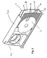
- the food slicer in Figure 1 shows a cuboid housing 2.
- the housing 2 is formed as a one-piece plastic injection molded part and comprises a rear wall 4, a bottom surface 2b, a top surface 2d and a rear, narrow-side housing wall 2c.
- the housing 2 further comprises a front wall 3, which is hidden in the view in Figure 1 and therefore not visible.
- the cuboidal housing 2 is closed at its front by a removable housing wall 2a, a narrow side wall of the housing 2 forms.
- the removable housing wall 2a has the end wall 10 of the food slicer.
- a key switch 22 is arranged on a top surface of the end wall 10.
- the end wall 10 carries a locking mechanism 23rd
- the cuboid housing 2 is shown.
- the cuboid housing 2 is formed as a one-piece plastic injection molded part.
- the housing 2 has a front wall 3 and a rear wall 4, which is arranged at a distance from the front wall 3. Between front wall 3 and rear wall 4, a gap 5 is formed. This space 5 is accessible via an opening 8.
- a carrier 9, as shown for example in Figure 3 in the space 5 of the cuboid housing 2 can be inserted.
- guides 11 are formed, on which the carrier 9 of Figure 3 in the housing 2 can be inserted.
- the guides 11 are formed as integrally molded strips on the inner walls of the front wall 3 and the rear wall 4.
- a circular blade not shown, can be used.
- FIG. 3 shows a carrier 9 according to the invention.
- the carrier 9 is designed as a one-piece plastic injection molded part and comprises the removable housing wall 2a or the end wall C.
- resilient latching hooks 16 are formed which have retaining lugs 15.
- the retaining lugs 15 engage in associated latching means 12 on the inner sides of the housing 2 a.
- the locking means 12 are formed as depressions on the inside of the front wall 3 and the rear wall 4, as seen in Figure 2.
- the carrier 9 is formed together with the end wall 10 as a one-piece component.
- the carrier 9 comprises a bearing plate 20 which carries a gear 6 and a drive motor 7.
- the transmission 6 comprises a bearing 18, in which a drive pinion 19 is inserted.
- a further storage 17 for a circular blade 5 is arranged.
- the first bearing 17 is held by means of a second one-piece component 21 at a distance from the second bearing 18. All components comprising the drive motor 7, the transmission 6, the first bearing 17 and the second bearing 18 are pre-assembled on the carrier 9.
- a push-button switch 22 is integrated into the removable housing wall 2a.
- the end wall 10 has a locking mechanism 23 which blocks the key switch 22 in the engaged position.
- the completely pre-assembled unit as shown in Figure 3, is in the integrally formed, cuboid housing 2, as in Figure 2 is shown, can be inserted.
- the completely pre-assembled carrier 9 according to FIG. 3 can be inserted into the integrally formed cuboid housing 2.
- the inserted into the housing 2 carrier 9 then forms the complete food slicer of Figure 1.
Landscapes
- Life Sciences & Earth Sciences (AREA)
- Forests & Forestry (AREA)
- Engineering & Computer Science (AREA)
- Mechanical Engineering (AREA)
- Food-Manufacturing Devices (AREA)
- Crushing And Pulverization Processes (AREA)
- Control And Other Processes For Unpacking Of Materials (AREA)
- Knives (AREA)
Claims (9)
- Trancheuse universelle comprenant un boîtier (2) ayant au moins approximativement la forme d'un parallélépipède rectangle et comportant une paroi arrière (4) et une paroi avant (3) située à distance de la paroi arrière (4), ce qui constitue un espace libre (5) qui est accessible par une paroi amovible (2a) du boîtier et sert à loger une unité d'entraînement, laquelle comporte un moteur d'entraînement (7) et un mécanisme de transmission (6) et est prévue pour entraîner une lame circulaire (1) qui est associée à la paroi avant (3), la paroi amovible (2a) du boîtier étant constituée par la paroi frontale (10) du boîtier et les autres parois (2b, 2c, 2d) du boîtier étant assemblées entre elles pour constituer une unité monobloc et un support (9), réalisé en tant que composant monobloc avec la paroi frontale (10) et recevant le mécanisme de transmission (6) et le moteur d'entraînement (7), pouvant être inséré dans le boîtier 2, caractérisée en ce que le composant monobloc présente des nervures de rigidification dont le tracé est situé entre le support (9) et la paroi frontale (10).
- Trancheuse universelle selon la revendication 1, caractérisée en ce que le support (9) prend appui sur au moins un côté intérieur du boîtier (2).
- Trancheuse universelle selon la revendication 2, caractérisée en ce qu'un guidage (11) est prévu sur le côté intérieur du boîtier (2) et le support (9) peut être inséré dans le boîtier (2) au moyen du guidage (11).
- Trancheuse universelle selon la revendication 2 ou 3, caractérisée en ce que le boîtier (2) comporte des moyens d'enclenchement (12) et le support (9) est fixé dans les moyens d'enclenchement (12).
- Trancheuse universelle selon la revendication 4, caractérisée en ce que les moyens d'enclenchement (12) sont réalisés en tant que creux (14) sur le côté intérieur du boîtier (2) dans lesquels s'engagent des ergots de retenue (15) qui sont fixés au support (9) au moyen de crochets d'enclenchement élastiques (16).
- Trancheuse universelle selon la revendication 4 ou 5, caractérisée en ce que les moyens d'enclenchement (12) sont situés à proximité d'un premier logement (17) pour la lame circulaire (5).
- Trancheuse universelle selon l'une des revendications 4 à 6, caractérisée en ce que les moyens d'enclenchement (12) sont situés à proximité d'un deuxième logement (18) pour un pignon d'entraînement (19).
- Trancheuse universelle selon la revendication 1, caractérisée en ce que le support (9) est assemblé à une plaque d'appui (20) qui porte le mécanisme de transmission (6) et le moteur d'entraînement (7).
- Trancheuse universelle selon la revendication 1, caractérisée en ce que le composant monobloc est réalisé en tant que pièce obtenue par moulage par injection de matière plastique.
Applications Claiming Priority (3)
| Application Number | Priority Date | Filing Date | Title |
|---|---|---|---|
| DE2002108489 DE10208489A1 (de) | 2002-02-27 | 2002-02-27 | Allesschneider mit einem Einschubgehäuse |
| DE10208489 | 2002-02-27 | ||
| PCT/EP2003/001754 WO2003072319A1 (fr) | 2002-02-27 | 2003-02-20 | Trancheuse dotee d'un boitier d'insertion |
Publications (2)
| Publication Number | Publication Date |
|---|---|
| EP1483090A1 EP1483090A1 (fr) | 2004-12-08 |
| EP1483090B1 true EP1483090B1 (fr) | 2007-09-05 |
Family
ID=27675063
Family Applications (1)
| Application Number | Title | Priority Date | Filing Date |
|---|---|---|---|
| EP03717191A Expired - Lifetime EP1483090B1 (fr) | 2002-02-27 | 2003-02-20 | Trancheuse dotee d'un boitier d'insertion |
Country Status (11)
| Country | Link |
|---|---|
| US (1) | US20050051006A1 (fr) |
| EP (1) | EP1483090B1 (fr) |
| AT (1) | ATE372193T1 (fr) |
| AU (1) | AU2003221485A1 (fr) |
| DE (2) | DE10208489A1 (fr) |
| HR (1) | HRP20040771B1 (fr) |
| PL (1) | PL206887B1 (fr) |
| RU (1) | RU2313443C2 (fr) |
| SI (1) | SI1483090T1 (fr) |
| WO (1) | WO2003072319A1 (fr) |
| YU (1) | YU72304A (fr) |
Families Citing this family (10)
| Publication number | Priority date | Publication date | Assignee | Title |
|---|---|---|---|---|
| DE10358674A1 (de) * | 2003-12-12 | 2005-07-07 | Leader Time Srl | Schneidvorrichtung |
| US20070044612A1 (en) * | 2005-08-26 | 2007-03-01 | Somal Hardev S | Gage plate adjustment mechanism for a food slicer |
| US20070044611A1 (en) * | 2005-08-26 | 2007-03-01 | Bondarowicz Frank A | Food slicer |
| DE102009030227A1 (de) * | 2009-06-23 | 2011-01-05 | Gebr. Graef Gmbh & Co Kg | Schneidemaschine für Lebensmittel |
| DE102010052787A1 (de) * | 2010-11-27 | 2012-05-31 | Bizerba Gmbh & Co Kg | Professionelle Scheibenschneidmaschine mit kompaktem Motor-Getriebe-Einschub |
| DE102011115429A1 (de) * | 2011-10-08 | 2013-04-11 | Bizerba Gmbh & Co. Kg | Verfahren zur Herstellung einer Lebensmittelschneidemaschine |
| USD690564S1 (en) | 2011-10-10 | 2013-10-01 | Calphalon Corporation | Mandolin |
| JP6411303B2 (ja) * | 2015-09-08 | 2018-10-24 | 株式会社ベンリナー | スライサー |
| RU186996U1 (ru) * | 2018-10-04 | 2019-02-12 | Ньургун Павлович Макаров | Ломтерезка для крупноразмерных пищевых продуктов |
| US11491563B2 (en) * | 2020-10-13 | 2022-11-08 | Trent N. Butcher | Cutting systems and related methods |
Family Cites Families (11)
| Publication number | Priority date | Publication date | Assignee | Title |
|---|---|---|---|---|
| DE1778553A1 (de) * | 1968-05-10 | 1971-12-16 | Ritterwerk F Ritter & Sohn | Elektrisch angetriebene Brot-und Aufschnittschneidemaschine |
| DE6906246U (de) * | 1969-02-18 | 1970-04-16 | Metallindustrie Denkingen Gebr | Schneidmaschine |
| DE2629352C2 (de) * | 1976-06-30 | 1985-02-07 | Bosch-Siemens Hausgeräte GmbH, 7000 Stuttgart | Schneidmaschine für Lebensmittel, insbesondere Haushalts-Schneidemaschine |
| JPS5524857A (en) * | 1978-08-08 | 1980-02-22 | Aichi Electric Mfg | Motor food slice machine |
| US4273013A (en) * | 1979-07-09 | 1981-06-16 | Sunbeam Corporation | Slicing machine |
| US4345498A (en) * | 1980-06-18 | 1982-08-24 | Rival Manufacturing Company | Food slicing machine |
| US4520703A (en) * | 1982-05-18 | 1985-06-04 | Bosch-Siemens Hausgeraete Gmbh | Electromotively driven household slicing machine for food |
| IT8320468U1 (it) * | 1983-01-14 | 1984-07-14 | Cavalli Alfredo | Dispositivo di sicurezza per impedire l'accesso involontario alle lame di taglio e utensili simili di un apparecchio elettrodomestico polifunzionale |
| DE3304611A1 (de) * | 1983-02-10 | 1984-08-16 | Bizerba-Werke Wilhelm Kraut GmbH & Co KG, 7460 Balingen | Vorrichtung zur kuehlung des elektrischen antriebsmotors fuer das kreismesser einer aufschnitt-schneidemaschine |
| US5026335A (en) * | 1989-03-03 | 1991-06-25 | Deere & Company | Downshifting work vehicle using differential lock switch |
| EP0386393A1 (fr) * | 1989-03-10 | 1990-09-12 | Angela Tognoli | Dispositif à trancher |
-
2002
- 2002-02-27 DE DE2002108489 patent/DE10208489A1/de not_active Withdrawn
-
2003
- 2003-02-20 EP EP03717191A patent/EP1483090B1/fr not_active Expired - Lifetime
- 2003-02-20 DE DE50308116T patent/DE50308116D1/de not_active Expired - Lifetime
- 2003-02-20 AT AT03717191T patent/ATE372193T1/de active
- 2003-02-20 RU RU2004124524A patent/RU2313443C2/ru not_active IP Right Cessation
- 2003-02-20 WO PCT/EP2003/001754 patent/WO2003072319A1/fr not_active Ceased
- 2003-02-20 SI SI200331037T patent/SI1483090T1/sl unknown
- 2003-02-20 AU AU2003221485A patent/AU2003221485A1/en not_active Abandoned
- 2003-02-20 HR HRP20040771AA patent/HRP20040771B1/xx not_active IP Right Cessation
- 2003-02-20 YU YUP72304 patent/YU72304A/sh unknown
- 2003-02-20 PL PL369974A patent/PL206887B1/pl unknown
-
2004
- 2004-08-27 US US10/928,222 patent/US20050051006A1/en not_active Abandoned
Also Published As
| Publication number | Publication date |
|---|---|
| DE50308116D1 (de) | 2007-10-18 |
| WO2003072319A1 (fr) | 2003-09-04 |
| DE10208489A1 (de) | 2003-09-04 |
| RU2313443C2 (ru) | 2007-12-27 |
| YU72304A (sh) | 2006-03-03 |
| PL206887B1 (pl) | 2010-10-29 |
| SI1483090T1 (sl) | 2008-02-29 |
| US20050051006A1 (en) | 2005-03-10 |
| AU2003221485A1 (en) | 2003-09-09 |
| EP1483090A1 (fr) | 2004-12-08 |
| PL369974A1 (pl) | 2005-05-02 |
| RU2004124524A (ru) | 2005-06-10 |
| HRP20040771A2 (en) | 2005-02-28 |
| HRP20040771B1 (hr) | 2012-06-30 |
| ATE372193T1 (de) | 2007-09-15 |
Similar Documents
| Publication | Publication Date | Title |
|---|---|---|
| EP1483090B1 (fr) | Trancheuse dotee d'un boitier d'insertion | |
| EP0409944B1 (fr) | Systeme d'essuie-glace | |
| EP2235455B1 (fr) | Appareil frigorifique ménager présentant au moins un balconnet | |
| EP2464926B1 (fr) | Balconnet pour un appareil de froid | |
| DE3007760A1 (de) | Kotfluegelaufbau | |
| EP2005092A2 (fr) | Appareil frigorifique à espace intérieur subdivisé | |
| EP1187734A1 (fr) | Piece support en matiere plastique moulee par injection sur le tole interieure de portiere de vehicules pour eviter que l'humidite ne penetre et procede permettant de produire ladite piece | |
| WO2009071342A1 (fr) | Appareil réfrigérant | |
| EP2220446B1 (fr) | Appareil réfrigérant | |
| EP0769425B1 (fr) | Boítier de sac gonflable en forme d'auge | |
| EP0854804A1 (fr) | Dispositif de commande d'au moins deux essuie-glaces d'un vehicule | |
| DE102016123889A1 (de) | Verbindungsanordnung zum Verbinden eines Pfostens mit einem Rahmenprofil eines Fensters oder einer Türe aus Kunststoff | |
| EP1895252B1 (fr) | Appareil de réfrigération et/ou de refroidissement | |
| EP2464928B1 (fr) | Appareil de froid | |
| EP1030144B1 (fr) | Paroi avec éléments de soutien | |
| DE102010002159B4 (de) | Vorrichtung zum Verbinden einer Antriebseinheit für eine Verstelleinrichtung eines Kraftfahrzeugsitzes mit der Festigkeitsstruktur des Kraftfahrzeugsitzes | |
| EP3537077B1 (fr) | Compartiment de stockage pour produits à réfrigérer pourvu d'un cadre en l, porte ainsi qu'appareil de refroidissement électroménager | |
| EP3239632A1 (fr) | Appareil de froid et porte pour un appareil de froid | |
| EP1095232A1 (fr) | Compartiment de rangement | |
| EP2023063A2 (fr) | Elément de fermeture de bord de porte d'une porte d'appareil ménager | |
| EP3760954A1 (fr) | Dispositif formant appareil électroménager | |
| EP1657110A1 (fr) | Barre pour le toit de véhicules de secours | |
| DE3743916A1 (de) | Schneidemaschine, insbesondere elektromotorisch angetriebene haushalt-schneidemaschine | |
| DE102016224985A1 (de) | Haushaltsgerätevorrichtung | |
| DE1103453B (de) | Motorgetriebeblock fuer elektrische Haushaltgeraete geringer Leistung |
Legal Events
| Date | Code | Title | Description |
|---|---|---|---|
| PUAI | Public reference made under article 153(3) epc to a published international application that has entered the european phase |
Free format text: ORIGINAL CODE: 0009012 |
|
| 17P | Request for examination filed |
Effective date: 20040927 |
|
| AK | Designated contracting states |
Kind code of ref document: A1 Designated state(s): AT BE BG CH CY CZ DE DK EE ES FI FR GB GR HU IE IT LI LU MC NL PT SE SI SK TR |
|
| AX | Request for extension of the european patent |
Extension state: AL LT LV MK RO |
|
| GRAP | Despatch of communication of intention to grant a patent |
Free format text: ORIGINAL CODE: EPIDOSNIGR1 |
|
| GRAS | Grant fee paid |
Free format text: ORIGINAL CODE: EPIDOSNIGR3 |
|
| GRAA | (expected) grant |
Free format text: ORIGINAL CODE: 0009210 |
|
| AK | Designated contracting states |
Kind code of ref document: B1 Designated state(s): AT BE BG CH CY CZ DE DK EE ES FI FR GB GR HU IE IT LI LU MC NL PT SE SI SK TR |
|
| REG | Reference to a national code |
Ref country code: GB Ref legal event code: FG4D Free format text: NOT ENGLISH |
|
| REG | Reference to a national code |
Ref country code: CH Ref legal event code: EP |
|
| REF | Corresponds to: |
Ref document number: 50308116 Country of ref document: DE Date of ref document: 20071018 Kind code of ref document: P |
|
| REG | Reference to a national code |
Ref country code: IE Ref legal event code: FG4D Free format text: LANGUAGE OF EP DOCUMENT: GERMAN |
|
| ET | Fr: translation filed | ||
| REG | Reference to a national code |
Ref country code: SE Ref legal event code: TRGR |
|
| PG25 | Lapsed in a contracting state [announced via postgrant information from national office to epo] |
Ref country code: ES Free format text: LAPSE BECAUSE OF FAILURE TO SUBMIT A TRANSLATION OF THE DESCRIPTION OR TO PAY THE FEE WITHIN THE PRESCRIBED TIME-LIMIT Effective date: 20071216 Ref country code: FI Free format text: LAPSE BECAUSE OF FAILURE TO SUBMIT A TRANSLATION OF THE DESCRIPTION OR TO PAY THE FEE WITHIN THE PRESCRIBED TIME-LIMIT Effective date: 20070905 |
|
| NLV1 | Nl: lapsed or annulled due to failure to fulfill the requirements of art. 29p and 29m of the patents act | ||
| GBV | Gb: ep patent (uk) treated as always having been void in accordance with gb section 77(7)/1977 [no translation filed] | ||
| REG | Reference to a national code |
Ref country code: IE Ref legal event code: FD4D |
|
| PG25 | Lapsed in a contracting state [announced via postgrant information from national office to epo] |
Ref country code: GR Free format text: LAPSE BECAUSE OF FAILURE TO SUBMIT A TRANSLATION OF THE DESCRIPTION OR TO PAY THE FEE WITHIN THE PRESCRIBED TIME-LIMIT Effective date: 20071206 Ref country code: NL Free format text: LAPSE BECAUSE OF FAILURE TO SUBMIT A TRANSLATION OF THE DESCRIPTION OR TO PAY THE FEE WITHIN THE PRESCRIBED TIME-LIMIT Effective date: 20070905 |
|
| PG25 | Lapsed in a contracting state [announced via postgrant information from national office to epo] |
Ref country code: PT Free format text: LAPSE BECAUSE OF FAILURE TO SUBMIT A TRANSLATION OF THE DESCRIPTION OR TO PAY THE FEE WITHIN THE PRESCRIBED TIME-LIMIT Effective date: 20080206 Ref country code: GB Free format text: LAPSE BECAUSE OF FAILURE TO SUBMIT A TRANSLATION OF THE DESCRIPTION OR TO PAY THE FEE WITHIN THE PRESCRIBED TIME-LIMIT Effective date: 20070905 Ref country code: IE Free format text: LAPSE BECAUSE OF FAILURE TO SUBMIT A TRANSLATION OF THE DESCRIPTION OR TO PAY THE FEE WITHIN THE PRESCRIBED TIME-LIMIT Effective date: 20070905 Ref country code: SK Free format text: LAPSE BECAUSE OF FAILURE TO SUBMIT A TRANSLATION OF THE DESCRIPTION OR TO PAY THE FEE WITHIN THE PRESCRIBED TIME-LIMIT Effective date: 20070905 |
|
| PLBE | No opposition filed within time limit |
Free format text: ORIGINAL CODE: 0009261 |
|
| STAA | Information on the status of an ep patent application or granted ep patent |
Free format text: STATUS: NO OPPOSITION FILED WITHIN TIME LIMIT |
|
| PG25 | Lapsed in a contracting state [announced via postgrant information from national office to epo] |
Ref country code: DK Free format text: LAPSE BECAUSE OF FAILURE TO SUBMIT A TRANSLATION OF THE DESCRIPTION OR TO PAY THE FEE WITHIN THE PRESCRIBED TIME-LIMIT Effective date: 20070905 |
|
| 26N | No opposition filed |
Effective date: 20080606 |
|
| BERE | Be: lapsed |
Owner name: BSH BOSCH UND SIEMENS HAUSGERATE G.M.B.H. Effective date: 20080228 |
|
| REG | Reference to a national code |
Ref country code: CH Ref legal event code: PL |
|
| PG25 | Lapsed in a contracting state [announced via postgrant information from national office to epo] |
Ref country code: CH Free format text: LAPSE BECAUSE OF NON-PAYMENT OF DUE FEES Effective date: 20080229 Ref country code: MC Free format text: LAPSE BECAUSE OF NON-PAYMENT OF DUE FEES Effective date: 20080228 Ref country code: LI Free format text: LAPSE BECAUSE OF NON-PAYMENT OF DUE FEES Effective date: 20080229 |
|
| PG25 | Lapsed in a contracting state [announced via postgrant information from national office to epo] |
Ref country code: EE Free format text: LAPSE BECAUSE OF FAILURE TO SUBMIT A TRANSLATION OF THE DESCRIPTION OR TO PAY THE FEE WITHIN THE PRESCRIBED TIME-LIMIT Effective date: 20070905 |
|
| PG25 | Lapsed in a contracting state [announced via postgrant information from national office to epo] |
Ref country code: BE Free format text: LAPSE BECAUSE OF NON-PAYMENT OF DUE FEES Effective date: 20080228 |
|
| PG25 | Lapsed in a contracting state [announced via postgrant information from national office to epo] |
Ref country code: CY Free format text: LAPSE BECAUSE OF FAILURE TO SUBMIT A TRANSLATION OF THE DESCRIPTION OR TO PAY THE FEE WITHIN THE PRESCRIBED TIME-LIMIT Effective date: 20070905 |
|
| PG25 | Lapsed in a contracting state [announced via postgrant information from national office to epo] |
Ref country code: BG Free format text: LAPSE BECAUSE OF FAILURE TO SUBMIT A TRANSLATION OF THE DESCRIPTION OR TO PAY THE FEE WITHIN THE PRESCRIBED TIME-LIMIT Effective date: 20071205 |
|
| PG25 | Lapsed in a contracting state [announced via postgrant information from national office to epo] |
Ref country code: HU Free format text: LAPSE BECAUSE OF FAILURE TO SUBMIT A TRANSLATION OF THE DESCRIPTION OR TO PAY THE FEE WITHIN THE PRESCRIBED TIME-LIMIT Effective date: 20080306 Ref country code: LU Free format text: LAPSE BECAUSE OF NON-PAYMENT OF DUE FEES Effective date: 20080220 |
|
| PG25 | Lapsed in a contracting state [announced via postgrant information from national office to epo] |
Ref country code: IT Free format text: LAPSE BECAUSE OF NON-PAYMENT OF DUE FEES Effective date: 20080229 |
|
| PGFP | Annual fee paid to national office [announced via postgrant information from national office to epo] |
Ref country code: CZ Payment date: 20110209 Year of fee payment: 9 |
|
| PGFP | Annual fee paid to national office [announced via postgrant information from national office to epo] |
Ref country code: FR Payment date: 20120228 Year of fee payment: 10 |
|
| PGFP | Annual fee paid to national office [announced via postgrant information from national office to epo] |
Ref country code: SE Payment date: 20120221 Year of fee payment: 10 |
|
| REG | Reference to a national code |
Ref country code: SE Ref legal event code: EUG |
|
| PG25 | Lapsed in a contracting state [announced via postgrant information from national office to epo] |
Ref country code: SE Free format text: LAPSE BECAUSE OF NON-PAYMENT OF DUE FEES Effective date: 20130221 Ref country code: CZ Free format text: LAPSE BECAUSE OF NON-PAYMENT OF DUE FEES Effective date: 20130220 |
|
| REG | Reference to a national code |
Ref country code: FR Ref legal event code: ST Effective date: 20131031 |
|
| PG25 | Lapsed in a contracting state [announced via postgrant information from national office to epo] |
Ref country code: FR Free format text: LAPSE BECAUSE OF NON-PAYMENT OF DUE FEES Effective date: 20130228 |
|
| REG | Reference to a national code |
Ref country code: DE Ref legal event code: R081 Ref document number: 50308116 Country of ref document: DE Owner name: BSH HAUSGERAETE GMBH, DE Free format text: FORMER OWNER: BSH BOSCH UND SIEMENS HAUSGERAETE GMBH, 81739 MUENCHEN, DE Effective date: 20150407 |
|
| REG | Reference to a national code |
Ref country code: SI Ref legal event code: SP73 Owner name: BSH HAUSGERAETE GMBH; DE Effective date: 20150529 |
|
| REG | Reference to a national code |
Ref country code: AT Ref legal event code: HC Ref document number: 372193 Country of ref document: AT Kind code of ref document: T Owner name: BSH HAUSGERAETE GMBH, DE Effective date: 20150528 |
|
| PGFP | Annual fee paid to national office [announced via postgrant information from national office to epo] |
Ref country code: DE Payment date: 20180228 Year of fee payment: 16 |
|
| PGFP | Annual fee paid to national office [announced via postgrant information from national office to epo] |
Ref country code: SI Payment date: 20180209 Year of fee payment: 16 Ref country code: AT Payment date: 20180220 Year of fee payment: 16 |
|
| PGFP | Annual fee paid to national office [announced via postgrant information from national office to epo] |
Ref country code: TR Payment date: 20190207 Year of fee payment: 17 |
|
| REG | Reference to a national code |
Ref country code: DE Ref legal event code: R119 Ref document number: 50308116 Country of ref document: DE |
|
| REG | Reference to a national code |
Ref country code: AT Ref legal event code: MM01 Ref document number: 372193 Country of ref document: AT Kind code of ref document: T Effective date: 20190220 |
|
| PG25 | Lapsed in a contracting state [announced via postgrant information from national office to epo] |
Ref country code: SI Free format text: LAPSE BECAUSE OF NON-PAYMENT OF DUE FEES Effective date: 20190221 |
|
| REG | Reference to a national code |
Ref country code: SI Ref legal event code: KO00 Effective date: 20191007 |
|
| PG25 | Lapsed in a contracting state [announced via postgrant information from national office to epo] |
Ref country code: AT Free format text: LAPSE BECAUSE OF NON-PAYMENT OF DUE FEES Effective date: 20190220 |
|
| PG25 | Lapsed in a contracting state [announced via postgrant information from national office to epo] |
Ref country code: DE Free format text: LAPSE BECAUSE OF NON-PAYMENT OF DUE FEES Effective date: 20190903 |
|
| PG25 | Lapsed in a contracting state [announced via postgrant information from national office to epo] |
Ref country code: TR Free format text: LAPSE BECAUSE OF NON-PAYMENT OF DUE FEES Effective date: 20200220 |