EP1483984A9 - Glissière pour tiroirs - Google Patents
Glissière pour tiroirs Download PDFInfo
- Publication number
- EP1483984A9 EP1483984A9 EP03012770A EP03012770A EP1483984A9 EP 1483984 A9 EP1483984 A9 EP 1483984A9 EP 03012770 A EP03012770 A EP 03012770A EP 03012770 A EP03012770 A EP 03012770A EP 1483984 A9 EP1483984 A9 EP 1483984A9
- Authority
- EP
- European Patent Office
- Prior art keywords
- drawer
- pull
- function carrier
- out guide
- decor
- Prior art date
- Legal status (The legal status is an assumption and is not a legal conclusion. Google has not performed a legal analysis and makes no representation as to the accuracy of the status listed.)
- Granted
Links
Images




Classifications
-
- A—HUMAN NECESSITIES
- A47—FURNITURE; DOMESTIC ARTICLES OR APPLIANCES; COFFEE MILLS; SPICE MILLS; SUCTION CLEANERS IN GENERAL
- A47B—TABLES; DESKS; OFFICE FURNITURE; CABINETS; DRAWERS; GENERAL DETAILS OF FURNITURE
- A47B88/00—Drawers for tables, cabinets or like furniture; Guides for drawers
- A47B88/40—Sliding drawers; Slides or guides therefor
- A47B88/423—Fastening devices for slides or guides
- A47B88/427—Fastening devices for slides or guides at drawer side
Definitions
- the invention relates to a pull-out for drawers, in particular for Furniture drawers, according to the preamble of the independent claims.
- Pull-out guides for furniture drawers are known from the prior art, which are mounted in drawer side walls. It is also known in or on the Pull-out guides Arrangements with various functions, such as a Page balance function, a failover function, a high tear function, an end-stop function, automatic retraction or damping function.
- the pull-out guide in the region of the Drawer front attached part of the drawer rail a function carrier, the at least one functional element for receiving, holding and / or Connecting parts of the drawer and / or at least one Functional element for the provision, support, and / or realization of Has drawer functions.
- Such a feature provided on the pull-out function can under other than a device for hanging and / or unhooking a Furniture drawer used by the pull-out with or without decor.
- the function carrier with one of the drawer rail adapted cross section in or in extension arranged the drawer rail and detachable or insoluble with this connected.
- the function carrier is on the drawer rail designed to be plugged.
- both the function carrier and the drawer rail positioning elements have, when plugging the function carrier on the drawer rail mesh.
- the function carrier is not separate form part connected to the drawer rail, but as integral Part of the drawer rail.
- the hanging and / or hanging of the function carrier in the drawer rail is done by inserting and / or pushing out of the function carrier in the drawer rail, with resilient tabs allow this insertion and / or pushing out.
- at least one elastically resilient tab is formed on the function carrier, which engages in an associated opening of the drawer rail.
- the resilient tab preferably has a step for this purpose, which can be latched to an edge of the opening of the drawer rail. Accordingly, the function carrier is released from the drawer rail by actuating the resilient tabs laterally and / or from top to bottom and removing the functional carrier from the drawer rail.
- the function carrier may have one or more devices for releasably connecting the pull-out guide to the drawer side wall and / or the decor.
- a side centering for tolerance compensation in the function carrier is provided in order to position the pull-out within the width of the decor can.
- the function carrier comprises one or more support surfaces, which are arranged on the decor, resilient tabs, wherein the resilient tabs engage on one or both sides of the function carrier and lock the decor. This ensures a longitudinal attachment of the decor on the function carrier.
- the support surfaces may preferably be formed stepwise, resulting in the determination of the decoration in the longitudinal direction of the pull-out different locking positions for the resilient tabs of the decor.
- a blocking of the side centering for tolerance compensation in the function carrier is also provided to allow a secure locking of the previously centered pull-out within the decor.
- a longitudinal edge extending in the longitudinal direction is formed, engage the attached to the decor resilient locking claws.
- the edge may be stepped, resulting in different Detent positions for the locking claws for determining the decoration in the transverse direction of the Pull-out guide result.
- the function carrier has a Fail-safe function on, with a nose of the decor on a resilient flap of the function carrier is supported, the closed Condition of the pull-out can move only slightly, because he from the Middle rail is blocked. This allows the drawer to be overhead do not hang it yourself.
- the pull-out guide is in the open state, the Flaps released and may spring because the middle rail is no longer behind it lies. In this case, the drawer can be unhooked from the drawer rail become.
- a function in the function carrier for unhooking the Drawer provided by lifting.
- One or more fingers one with the Drawer side wall connected part engage in resilient lobes of the Function holder.
- Lifting the whole drawer releases the finger from the springy rags and the drawer from the drawer rail.
- the Hanging by opening the drawer is only possible if the Extractor is pulled out, otherwise the above described Failure prevents lifting the drawer.
- the pull-out guide has an end stop, which is attached to the underside of the function carrier and with a Stop surface meets directly on the carcass rail.
- a relies Front surface of the end stop on the front fastening device of the Drawer off.
- the abutment surface of the end stop can be elastic or comprise an inserted or molded elastic attachment.
- the stop surface on or arranged on an adjustable element can be designed as a thumbscrew.
- the stop surface is supported by a front surface of the End stop preferably directly to parts of the decor or the Front fastening device from.
- Another feature is that in or on the function carrier a holder for a damping element and / or automatic retraction is provided.
- the function carrier has a cavity in which the damping element and / or the automatic retraction is added.
- the damping element and / or the automatic retraction safely remains in the intended position, it is locked on the function carrier or in the cavity, for example by means of a latching connection.
- the damping element and / or the automatic retraction is arranged such that its bottom is supported on parts of the drawer side wall.
- the function carrier according to the invention for drawer extension guides especially for furniture drawers with drawer side wall with or without Decor, characterized by being in the area of the drawer front Assigned part of the drawer rail is arranged and at least one Functional element for receiving, holding and / or connection of parts of Drawer and / or at least one functional element for providing, Having support and / or realization of drawer functions.
- the decor itself has arranged on the side surfaces resilient tabs for lateral centering, which interact with associated contact surfaces of the drawer rail or an existing on the drawer rail function carrier.
- resiliently formed locking claws may be provided in the upper region, which are supported on associated edges of the drawer rail or an existing on the drawer rail function carrier.
- the decor may have a nose which is supported on a resilient flap of the drawer rail or an existing on the drawer rail function carrier, and thereby prevents a hanging of the drawer in an overhead arrangement of the body.
- FIG. 1 shows a perspective view of an embodiment of the invention pull-out guide according to the invention 2.
- the pull-out 2 includes in known manner, a so-called drawer rail 3, with a drawer (not shown), or represents a part of this. Further includes the pull-out 2 a so-called carcass rail 5, the z. B. by means Carcass adapters 36 is attached to a furniture body (not shown). Between the carcass rail 5 and the drawer rail 3 is located in the Usually a movably connected to this center rail 4, not in Figure 1 is visible. According to the invention is now in the drawer front facing part of the drawer rail 3, a function carrier 1 is arranged.
- the function carrier 1 comprises at least one functional element for receiving, Holder and / or connection of parts of the drawer or at least one Functional element for the provision, support and / or realization of Drawer features.
- the function carrier 1 can as shown in Figure 1 as separate part, preferably be designed as a plastic part, the detachable or undetachably connected to the drawer rail 3.
- the function carrier 1 but can also be an integral part of the drawer rail 3 and one piece be connected with this.
- Figures 2, 3 and 4 show various enlarged views of Function carrier 1.
- the function carrier 1 has one of the drawer rail 3 adapted cross section and is in extension of the drawer rail. 3 attached to this and locked in the drawer rail 3.
- the locking function is characterized by lateral resilient tab 6, 6 'in connection with a stage 7, 7' realized, as will be described later.
- a centering or positioning element 8 which in a corresponding recess of the drawer rail 3 engages and the Function carrier 1 positioned in this. This will be explained later become.
- the resilient tabs 6, 6 'each have at their outer end a row of step-shaped bearing surfaces 9, 9', 9 ", at the upper part of the functional carrier 1, which is approximately opposite the resilient tabs 6, 6 ', lateral edges are in each case in stepped configuration 10, 10 ', 10 "arranged.
- a resilient tab 11 is provided on one side.
- an end stop 13 is provided which cooperates with a stop surface of the carcass rail 5 and limits the insertion of the pull-out guide 2.
- the end stop 13 On the side facing away from the drawer front 38, the end stop 13 has the actual abutment surface 14, which strikes the carcass rail 5, and on the side facing the drawer front 38, a front surface 15, which is supported on parts of the decor or the front fastening device 33 of the drawer. as described below.
- a cavity 23 is further arranged, which is suitable for receiving various devices for providing drawer functions, such. B. a damping device or automatic retraction serves.
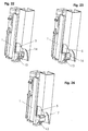
- Figures 5, 6 and 7 indicate the type of attachment of the function carrier 1 at the drawers 3.
- Figure 7 shows a perspective view of front end of the drawer rail 3 of the pull-2, in the Area of the function carrier 1 is attached.
- the drawer rail 3 is in formed in this example as a rectangular tube, which is open at the front and on the left and right sides each having a slot 25. In appropriate Distance to the slot 25 are also left and right openings 44th provided, which form a locking edge 24 at the front end.
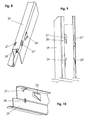
- Such a decor 29 is shown in Figures 8 to 10 and serves for Panel of the drawer side walls 30.
- the decor 29 is in this example formed approximately U-shaped with the closed end of the U the top and the open end of the U forms the underside in which the pull-out guide 2 is recorded.
- the decor 29 includes various functional elements that with corresponding functional elements of the functional carrier 1 interact.
- a nose 28 is provided, which is supported on the flap 11 and a Failover realized, as described below.
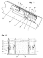
- FIG 11 is a perspective view, partially in longitudinal section, shown at the decor 29 on the pull-2 and the function carrier. 1 is attached.
- the pull-out guide 2 or the function carrier 1 are now inside the cavity of the decor 29. It can be seen that the end of the resilient tab 26 on the stepped support surfaces 9, 9 'and 9 " supported. As a result, a longitudinal attachment of the decor 29 on the Function carrier 1 guaranteed.
- the bearing surfaces 9, 9 'and 9 "result various locking positions for the resilient tabs 26, 26 ', so that the Decor 29 can be positioned in the longitudinal direction.
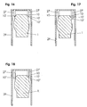
- FIGS. 12 to 15 Exemplary embodiments for different positions of the side centering of the decor 29 with respect to the function carrier 1 and the pull-out guide 2 are shown in FIGS. 12 to 15. It can be seen hinted the drawer bottom 37 and the drawer front 38, which rests against the function carriers 1 of the two pull-2. It can be seen the respective decor 29 on the left and right side, the resilient tabs 26 and 26 'create the bearing surfaces 9 of the function carrier 1. The bearing surfaces 9, 9 ', 9 "are step-shaped, so that a longitudinal compensation of the attachment of the decoration 29 is possible on the function carrier 1. By the two tabs 26 and 26', the decor 29 is centered laterally relative to the function carrier 1.
- Figure 12 shows a first position of the page centering in which the resilient Tabs 26, 26 'attack on the innermost and rearmost stage 9, wherein the Drawer bottom 37 has its desired width, so that the function carrier 1 exactly centered in the decor 29 is centered.
- FIG. 14 shows a third position of the page centering, with the Drawer bottom 37 is formed too wide, so that the function carrier. 1 each not centric but in the outward direction within the decor 29th located. Due to the length of the drawer, the tabs 26 snap on the foremost step 9 ".
- FIG. 15 shows a fourth position of the page centering, where FIG Drawer bottom 37 is formed too narrow, so that the function carrier 1 at the inside of the decor 29 are centered. Again, the tabs on the outermost level 9 ".
- Figure 16 corresponds to the installation position of the decoration 29 according to Figure 13, i. the Decor 29 is centered exactly above the function carrier 1. Grab this both locking claws 27, 27 ', for example, in the lowest step 10 "of the edges.
- FIG. 17 illustrates the situation according to FIG. 14 (for the left side of the drawer), i.e. the decor 29 is not centered with respect to the function carrier. 1 Therefore, the resilient locking claw 27 engages the uppermost stage 10, while the Blocking claw 27 'holds the function carrier 1 laterally and at the level 10 "rests.
- FIG. 18 shows the situation according to FIG. 15 (for the left side of the drawer), i.e. the decor 29 is offset from the function carrier 1 to the outside, so that the locking claw 27 at the lowest stage 10 "attacks while the Bulk claw 27 'rests against the top step 10.
- resilient tabs 26, 26 'and the locking claws 27, 27' and the respective associated bearing surfaces 9, 9 ', 9 "and edges 10, 10', 10" is a independent centering, alignment and locking of the decor 29 on the Function carrier 1 and the drawer rail 3 guaranteed.
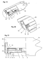
- Figures 19, 20 and 21 show an embodiment of the attachment of the Drawer or drawer side wall 30 on the function carrier 1 and thus on the Drawer rail 3.
- Function carrier 1 directed pin or finger 31 has.
- this finger is laterally and upward of two resilient Lobe 12 and 12 'held and thus holds the drawer side wall 30 at the Pull-out guide 2 fixed.
- the resilient tabs 12, 12 ' are upward, so that with the drawer pulled out, the finger 31 upwards out of engagement with the resilient tabs 12, 12 'can be lifted out, and the drawer so is unhooked from the drawer rail 3 and can be removed.
- the hook-shaped front fastening device 33 can be seen below, at the then the drawer front 38 is attached.
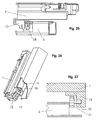
- end stop 13 is shown in more detail and described.
- the end stop 13 is located at the bottom of the Function carrier 1 and includes a stop surface 14, the slide-in the drawer in its end position on the carcass rail 5 abuts.
- Figure 23 shows and a resilient stop surface 16, while FIG 24 shows an elastic abutment surface in the form of an elastomeric part 17.
- a elastic or resilient design of the stop surface 14 ensures a quiet closing of the drawer and a certain reduction of kinetic energy.
- the stop surface of the end stop 13 can also be made adjustable be such that the front gap, i. the distance between drawer front 38 and Drawer rail 3 or body is adjustable.
- FIG. 25 shows this as Stop surface an adjustable wheel 18 having inclined steps, or is formed multi-level, each stage a certain adjustment distance equivalent.
- FIG. 26 shows an adjustable end stop by means of a resilient tongue 20, which can be changed by means of an adjusting screw 19 in position.
- FIG. 27 shows an adjustable end stop by means of a knurled screw 21, whose thread 22 is seated in the end stop 13.
- the solution according to FIGS. 25 and 27 are without tools, i. manually adjustable while at the solution according to Figure 26, a screwdriver is needed.
- the cavity 23 may, for. B. be used to a damping device 39, which absorbs the impact energy when closing the drawer, install.
- the energy is in the damping device 39 by means of a received movable piston 40.
- the damping device 39 is in the Cavity 23 is inserted and snapped on the front side and / or on the Rear side by means of corresponding spring tongues 41, 42, 43, with locking edges of the function carrier 1 interact, and is thus in the function carrier. 1 locked.
- the damping device 39 is set in the function carrier such that the bottom of which is supported on parts 32 of the drawer side wall 30 and thus the drawer energy is passed directly to the piston rod 40.
Landscapes
- Drawers Of Furniture (AREA)
Priority Applications (3)
| Application Number | Priority Date | Filing Date | Title |
|---|---|---|---|
| EP03012770.8A EP1483984B1 (fr) | 2003-06-05 | 2003-06-05 | Glissière pour tiroirs |
| AT0034504U AT7648U1 (de) | 2003-06-05 | 2004-05-11 | Ausziehführung für schubladen |
| US10/858,609 US7654625B2 (en) | 2003-06-05 | 2004-06-02 | Pull-out guide for drawers |
Applications Claiming Priority (1)
| Application Number | Priority Date | Filing Date | Title |
|---|---|---|---|
| EP03012770.8A EP1483984B1 (fr) | 2003-06-05 | 2003-06-05 | Glissière pour tiroirs |
Publications (3)
| Publication Number | Publication Date |
|---|---|
| EP1483984A1 EP1483984A1 (fr) | 2004-12-08 |
| EP1483984A9 true EP1483984A9 (fr) | 2005-04-27 |
| EP1483984B1 EP1483984B1 (fr) | 2017-08-09 |
Family
ID=33155160
Family Applications (1)
| Application Number | Title | Priority Date | Filing Date |
|---|---|---|---|
| EP03012770.8A Expired - Lifetime EP1483984B1 (fr) | 2003-06-05 | 2003-06-05 | Glissière pour tiroirs |
Country Status (3)
| Country | Link |
|---|---|
| US (1) | US7654625B2 (fr) |
| EP (1) | EP1483984B1 (fr) |
| AT (1) | AT7648U1 (fr) |
Cited By (1)
| Publication number | Priority date | Publication date | Assignee | Title |
|---|---|---|---|---|
| DE202011109550U1 (de) * | 2011-12-23 | 2013-03-25 | Grass Gmbh | Möbelbeschlag für ein bewegbares Möbelteil |
Families Citing this family (48)
| Publication number | Priority date | Publication date | Assignee | Title |
|---|---|---|---|---|
| US20050231083A1 (en) * | 2004-04-15 | 2005-10-20 | Garcie Kent C Jr | Undermount drawer slide |
| TWM265495U (en) * | 2004-10-15 | 2005-05-21 | Nan Juen Int Co Ltd | Locking structure with adjustable pulling force for slide rail |
| DE202005006724U1 (de) | 2005-02-14 | 2005-07-28 | Grass Gmbh | Schubladenführung |
| DE102005028674A1 (de) | 2005-06-21 | 2006-12-28 | BSH Bosch und Siemens Hausgeräte GmbH | Teleskopauszugsvorrichtung |
| DE202006004718U1 (de) * | 2006-03-22 | 2007-08-02 | Grass Gmbh | Vorrichtung für die Bewegungsbeeinflussung von zueinander bewegbaren Möbelteilen und Möbel |
| DE202007001782U1 (de) | 2006-09-08 | 2008-01-10 | Paul Hettich Gmbh & Co. Kg | Schubkasten |
| DE102006061096A1 (de) * | 2006-12-22 | 2008-06-26 | BSH Bosch und Siemens Hausgeräte GmbH | Teleskopauszug |
| MY142138A (en) * | 2007-08-06 | 2010-09-30 | Harn Marketing Sdn Bhd | Drawer assembly |
| DE202007012844U1 (de) | 2007-09-13 | 2007-11-29 | Kraft, Friedhelm | Handhabungsvorrichtung zur Handhabung von Werkstückträgern |
| US8911039B2 (en) | 2007-10-02 | 2014-12-16 | Paul Hettich Gmbh & Co. Kg | Pull-out guide having a self-retracting device |
| DE202008003328U1 (de) * | 2007-10-02 | 2009-02-12 | Paul Hettich Gmbh & Co. Kg | Auszugsführung mit einer Selbsteinzugsvorrichtung |
| DE202008004100U1 (de) * | 2008-03-25 | 2009-08-06 | Paul Hettich Gmbh & Co. Kg | Teleskopierbare Auszugsführung |
| DE102008054285A1 (de) * | 2008-11-03 | 2010-05-12 | Fujitsu Siemens Computers Gmbh | Halteanordnung für ein Einschubmodul und Trägerrack |
| DE102009001550A1 (de) * | 2009-03-13 | 2010-09-16 | BSH Bosch und Siemens Hausgeräte GmbH | Schienenauszugsvorrichtung und Muffel mit einer derartigen Schienenauszugsvorrichtung |
| AT509416B1 (de) * | 2010-02-03 | 2012-05-15 | Blum Gmbh Julius | Ausziehführung für eine schublade |
| AT509415B1 (de) | 2010-02-03 | 2013-12-15 | Blum Gmbh Julius | Anordnung mit einer Schublade und einer Ausziehführung für eine Schublade mit zumindest zwei Einrastpositionen |
| DE202010002621U1 (de) * | 2010-02-22 | 2011-08-18 | Grass Gmbh | Anbringvorrichtung für ein Möbelteil und Möbel |
| AT510773B1 (de) * | 2010-11-23 | 2014-09-15 | Blum Gmbh Julius | Schubladenanordnung mit einer an einem Schubladenbehälter vormontierten Behältnisschiene |
| AT510780A1 (de) * | 2010-11-23 | 2012-06-15 | Blum Gmbh Julius | Befestigungsvorrichtung für ein möbelteil |
| AT515690B1 (de) | 2014-06-23 | 2015-11-15 | Fulterer Gmbh | Ausziehführung |
| US9763518B2 (en) | 2014-08-29 | 2017-09-19 | Cisco Technology, Inc. | Systems and methods for damping a storage system |
| CN105581534A (zh) * | 2014-10-23 | 2016-05-18 | 川湖科技股份有限公司 | 滑轨总成及其安装装置 |
| US9853873B2 (en) | 2015-01-10 | 2017-12-26 | Cisco Technology, Inc. | Diagnosis and throughput measurement of fibre channel ports in a storage area network environment |
| EP3045074A1 (fr) * | 2015-01-14 | 2016-07-20 | King Slide Works Co., Ltd. | Ensemble de rail coulissant et dispositif de montage de celui-ci |
| US9900250B2 (en) | 2015-03-26 | 2018-02-20 | Cisco Technology, Inc. | Scalable handling of BGP route information in VXLAN with EVPN control plane |
| US10222986B2 (en) | 2015-05-15 | 2019-03-05 | Cisco Technology, Inc. | Tenant-level sharding of disks with tenant-specific storage modules to enable policies per tenant in a distributed storage system |
| US11588783B2 (en) | 2015-06-10 | 2023-02-21 | Cisco Technology, Inc. | Techniques for implementing IPV6-based distributed storage space |
| US10778765B2 (en) | 2015-07-15 | 2020-09-15 | Cisco Technology, Inc. | Bid/ask protocol in scale-out NVMe storage |
| CN106820684B (zh) * | 2015-12-03 | 2018-11-27 | 川湖科技股份有限公司 | 抽屉滑轨组件 |
| US9892075B2 (en) | 2015-12-10 | 2018-02-13 | Cisco Technology, Inc. | Policy driven storage in a microserver computing environment |
| US10140172B2 (en) | 2016-05-18 | 2018-11-27 | Cisco Technology, Inc. | Network-aware storage repairs |
| TWI577313B (zh) * | 2016-05-31 | 2017-04-11 | 川湖科技股份有限公司 | 抽屜滑軌 |
| US20170351639A1 (en) | 2016-06-06 | 2017-12-07 | Cisco Technology, Inc. | Remote memory access using memory mapped addressing among multiple compute nodes |
| CN107467925B (zh) * | 2016-06-07 | 2019-11-12 | 川湖科技股份有限公司 | 抽屉滑轨 |
| US10664169B2 (en) | 2016-06-24 | 2020-05-26 | Cisco Technology, Inc. | Performance of object storage system by reconfiguring storage devices based on latency that includes identifying a number of fragments that has a particular storage device as its primary storage device and another number of fragments that has said particular storage device as its replica storage device |
| US11563695B2 (en) | 2016-08-29 | 2023-01-24 | Cisco Technology, Inc. | Queue protection using a shared global memory reserve |
| US10545914B2 (en) | 2017-01-17 | 2020-01-28 | Cisco Technology, Inc. | Distributed object storage |
| US10243823B1 (en) | 2017-02-24 | 2019-03-26 | Cisco Technology, Inc. | Techniques for using frame deep loopback capabilities for extended link diagnostics in fibre channel storage area networks |
| US10713203B2 (en) | 2017-02-28 | 2020-07-14 | Cisco Technology, Inc. | Dynamic partition of PCIe disk arrays based on software configuration / policy distribution |
| US10254991B2 (en) | 2017-03-06 | 2019-04-09 | Cisco Technology, Inc. | Storage area network based extended I/O metrics computation for deep insight into application performance |
| CN108720378A (zh) | 2017-04-14 | 2018-11-02 | 新代产品公司 | 具有调节机构的柜组件 |
| US10303534B2 (en) | 2017-07-20 | 2019-05-28 | Cisco Technology, Inc. | System and method for self-healing of application centric infrastructure fabric memory |
| AT17935U1 (de) | 2017-08-17 | 2023-08-15 | Blum Gmbh Julius | Schubladenausziehführung |
| US10404596B2 (en) | 2017-10-03 | 2019-09-03 | Cisco Technology, Inc. | Dynamic route profile storage in a hardware trie routing table |
| DE102017123613A1 (de) * | 2017-10-11 | 2019-04-11 | Paul Hettich Gmbh & Co. Kg | Einzugsvorrichtung und Verfahren zum Öffnen und Schließen eines bewegbaren Möbelteils |
| US10942666B2 (en) | 2017-10-13 | 2021-03-09 | Cisco Technology, Inc. | Using network device replication in distributed storage clusters |
| AT520734B1 (de) | 2018-02-01 | 2019-07-15 | Blum Gmbh Julius | Ladenschiene für eine Schubladenausziehführung |
| DE102018108647A1 (de) * | 2018-04-11 | 2019-10-17 | Paul Hettich Gmbh & Co. Kg | Auszugsführung und Schubkastenserie |
Family Cites Families (26)
| Publication number | Priority date | Publication date | Assignee | Title |
|---|---|---|---|---|
| DE3347540A1 (de) * | 1983-12-30 | 1985-07-11 | Paul Hettich GmbH & Co, 4983 Kirchlengern | Schubkastenfuehrung |
| DE3632442A1 (de) * | 1986-09-24 | 1988-03-31 | Lautenschlaeger Kg Karl | Beschlag fuer die verstellbare halterung der laufschiene einer schubladen-ausziehfuehrung |
| DE3818225C2 (de) * | 1988-05-28 | 1996-04-18 | Miele & Cie | Schubladenführung mit einer Rücklaufsperre |
| US5207781A (en) * | 1989-04-03 | 1993-05-04 | Julius Blum Gesellschaft M.B.H. | Closing device for moving a drawer to a fully inserted position within a furniture body |
| US5281021A (en) | 1989-10-06 | 1994-01-25 | Julius Blum Gesellschaft M.B.H. | Arrangement for removably mounting a drawer to pull-out rails of drawer guide assemblies |
| AT399446B (de) * | 1991-04-30 | 1995-05-26 | Blum Gmbh Julius | Montagebeschlag für schubladen |
| DE4114708C2 (de) * | 1991-05-06 | 2000-11-30 | Lautenschlaeger Mepla Werke | Befestigungseinrichtung für Laufschienen von Schubladen-Ausziehführungen |
| DE9310582U1 (de) | 1993-07-15 | 1993-09-23 | Paul Hettich GmbH & Co, 32278 Kirchlengern | Rasteinrichtung fuer schubkaesten o.dgl. |
| ES2124437T3 (es) * | 1994-01-17 | 1999-02-01 | Blum Gmbh Julius | Cajon. |
| DE9402042U1 (de) * | 1994-02-08 | 1994-03-31 | Paul Hettich Gmbh & Co., 32278 Kirchlengern | Seitenzarge eines Schubkastens |
| AT404220B (de) | 1994-07-13 | 1998-09-25 | Alfit Ag | Vorrichtung zur befestigung einer auszugsführung |
| DE4433577A1 (de) | 1994-09-21 | 1996-03-28 | Hettich Paul Gmbh & Co | Möbelauszugsteil |
| DE9416504U1 (de) | 1994-10-14 | 1994-12-08 | Zibulla & Sohn Gmbh Raziol-Schmierungstechnik, 58642 Iserlohn | Vorrichtung zum Auftrag von flüssigen Medien, insbesondere von Befettungsmitteln, auf Werkstücke in Band- oder Platinenform |
| DE19538101A1 (de) * | 1995-10-13 | 1997-04-17 | Schock Metallwerk | Auszugführung |
| DE19828718A1 (de) | 1998-06-29 | 1999-12-30 | Bbp Kunststoffwerk | Rasteinrichtung zum lösbaren Befestigen von Schubkästen, Auszügen, Schüben o. dgl. an einer Führungsschiene |
| DE29914431U1 (de) | 1999-08-19 | 2000-02-24 | Kampmeier Kunststoff GmbH, 33129 Delbrück | Montageclip für Unterflurauszug/Teleskopauszug |
| DE19944639A1 (de) * | 1999-09-17 | 2001-03-22 | Hettich Paul Gmbh & Co | Befestigungsanordnung |
| AT409067B (de) * | 2000-03-02 | 2002-05-27 | Blum Gmbh Julius | Ausziehführung für schubladen |
| IT250443Y1 (it) * | 2000-09-19 | 2003-09-10 | Salice Arturo Spa | Dispositivo per la chiusura decelerata di parti di mobile scorrevoli |
| DE20204860U1 (de) * | 2002-03-26 | 2003-07-31 | Alfit AG, Götzis | Schubladen-Ausziehführungen mit Einzugsautomatik mit integrierter Dämpfung |
| MY131087A (en) * | 2002-05-17 | 2007-07-31 | Harn Marketing Sdn Bhd | Closing device for drawers |
| TW564720U (en) * | 2002-06-20 | 2003-12-01 | Nan Juen Int Co Ltd | Buffering and returning device for drawer rail |
| US6601933B1 (en) * | 2002-06-21 | 2003-08-05 | General Devices Co., Inc. | Telescoping slide with quick-mount system |
| DE10256133B4 (de) * | 2002-11-29 | 2005-03-24 | Grass Gmbh | Ausziehführungsgarnitur mit Schienensystem |
| AT413187B (de) * | 2003-04-25 | 2005-12-15 | Blum Gmbh Julius | Einzugsvorrichtung für schubladen |
| US6945618B2 (en) | 2003-06-02 | 2005-09-20 | Accuride International Inc. | Drawer slide adjustment mechanism |
-
2003
- 2003-06-05 EP EP03012770.8A patent/EP1483984B1/fr not_active Expired - Lifetime
-
2004
- 2004-05-11 AT AT0034504U patent/AT7648U1/de not_active IP Right Cessation
- 2004-06-02 US US10/858,609 patent/US7654625B2/en not_active Expired - Fee Related
Cited By (1)
| Publication number | Priority date | Publication date | Assignee | Title |
|---|---|---|---|---|
| DE202011109550U1 (de) * | 2011-12-23 | 2013-03-25 | Grass Gmbh | Möbelbeschlag für ein bewegbares Möbelteil |
Also Published As
| Publication number | Publication date |
|---|---|
| EP1483984A1 (fr) | 2004-12-08 |
| EP1483984B1 (fr) | 2017-08-09 |
| US20040245898A1 (en) | 2004-12-09 |
| AT7648U1 (de) | 2005-07-25 |
| US7654625B2 (en) | 2010-02-02 |
Similar Documents
| Publication | Publication Date | Title |
|---|---|---|
| EP1483984B1 (fr) | Glissière pour tiroirs | |
| EP0421458B1 (fr) | Tiroir | |
| EP2126494B1 (fr) | Appareil frigorifique | |
| EP2059148B1 (fr) | Tiroir | |
| EP0606564A1 (fr) | Dispositif de réglage de l'orientation de tiroirs et similaires | |
| EP3238568A1 (fr) | Système de tiroir | |
| EP2498643B1 (fr) | Dispositif pour l'accouplement d'un tiroir avec une glissière d'un guidage télescopique | |
| DE202017100200U1 (de) | Trennsteg für Energieführungsketten | |
| EP0041616A1 (fr) | Glissière télescopique pour support, tel que tiroirou similaire | |
| AT9972U1 (de) | Ausziehführung für schubladen | |
| EP3019046B1 (fr) | Glissière pour un tiroir | |
| DE202009005121U1 (de) | Ausstoßvorrichtung einer Ausziehführung und Ausziehführung | |
| EP0843064B1 (fr) | Ferrure pour un fenêtre | |
| DE20321444U1 (de) | Ausziehführung für Schubladen | |
| DE102017100742B3 (de) | Verriegelbare Kopplungsvorrichtung | |
| EP3773074B1 (fr) | Systeme de tiroir comprenant un rail sur lequel differents types de tiroirs peuvent etre installes | |
| DE102009033938B4 (de) | Wohndachfenster sowie Verfahren zum Befestigen eines Abdeckblechs | |
| EP3189749B1 (fr) | Guidage télescopique pour une partie de meuble mobile | |
| DE19828718A1 (de) | Rasteinrichtung zum lösbaren Befestigen von Schubkästen, Auszügen, Schüben o. dgl. an einer Führungsschiene | |
| DE102015203436A1 (de) | Dunstabzugshaube mit Auszugskörper | |
| EP3860400B1 (fr) | Dispositif de fixation servant à fixer un panneau d'un tiroir sur un châssis | |
| DE102021108249A1 (de) | Koppelelement, Schließsystem und Möbel | |
| DE202020104417U1 (de) | Auszugssperre | |
| AT408165B (de) | Elektrisches unterputz-installationseinbaugerät | |
| DE202013004939U1 (de) | Vorrichtung zur Positionierung und Fixierung eines beweglichen Möbelteils |
Legal Events
| Date | Code | Title | Description |
|---|---|---|---|
| PUAI | Public reference made under article 153(3) epc to a published international application that has entered the european phase |
Free format text: ORIGINAL CODE: 0009012 |
|
| AK | Designated contracting states |
Kind code of ref document: A1 Designated state(s): AT BE BG CH CY CZ DE DK EE ES FI FR GB GR HU IE IT LI LU MC NL PT RO SE SI SK TR |
|
| AX | Request for extension of the european patent |
Extension state: AL LT LV MK |
|
| 17P | Request for examination filed |
Effective date: 20050310 |
|
| AKX | Designation fees paid |
Designated state(s): AT BE BG CH CY CZ DE DK EE ES FI FR GB GR HU IE IT LI LU MC NL PT RO SE SI SK TR |
|
| 17Q | First examination report despatched |
Effective date: 20050804 |
|
| TPAC | Observations filed by third parties |
Free format text: ORIGINAL CODE: EPIDOSNTIPA |
|
| STAA | Information on the status of an ep patent application or granted ep patent |
Free format text: STATUS: EXAMINATION IS IN PROGRESS |
|
| REG | Reference to a national code |
Ref country code: DE Ref legal event code: R079 Ref document number: 50315688 Country of ref document: DE Free format text: PREVIOUS MAIN CLASS: A47B0088040000 Ipc: A47B0088427000 |
|
| GRAP | Despatch of communication of intention to grant a patent |
Free format text: ORIGINAL CODE: EPIDOSNIGR1 |
|
| STAA | Information on the status of an ep patent application or granted ep patent |
Free format text: STATUS: GRANT OF PATENT IS INTENDED |
|
| RIC1 | Information provided on ipc code assigned before grant |
Ipc: A47B 88/427 20170101AFI20170210BHEP |
|
| INTG | Intention to grant announced |
Effective date: 20170320 |
|
| GRAS | Grant fee paid |
Free format text: ORIGINAL CODE: EPIDOSNIGR3 |
|
| GRAA | (expected) grant |
Free format text: ORIGINAL CODE: 0009210 |
|
| STAA | Information on the status of an ep patent application or granted ep patent |
Free format text: STATUS: THE PATENT HAS BEEN GRANTED |
|
| AK | Designated contracting states |
Kind code of ref document: B1 Designated state(s): AT BE BG CH CY CZ DE DK EE ES FI FR GB GR HU IE IT LI LU MC NL PT RO SE SI SK TR |
|
| REG | Reference to a national code |
Ref country code: GB Ref legal event code: FG4D Free format text: NOT ENGLISH |
|
| REG | Reference to a national code |
Ref country code: CH Ref legal event code: EP Ref country code: AT Ref legal event code: REF Ref document number: 915876 Country of ref document: AT Kind code of ref document: T Effective date: 20170815 |
|
| REG | Reference to a national code |
Ref country code: IE Ref legal event code: FG4D Free format text: LANGUAGE OF EP DOCUMENT: GERMAN |
|
| REG | Reference to a national code |
Ref country code: DE Ref legal event code: R096 Ref document number: 50315688 Country of ref document: DE |
|
| REG | Reference to a national code |
Ref country code: NL Ref legal event code: MP Effective date: 20170809 |
|
| PG25 | Lapsed in a contracting state [announced via postgrant information from national office to epo] |
Ref country code: NL Free format text: LAPSE BECAUSE OF FAILURE TO SUBMIT A TRANSLATION OF THE DESCRIPTION OR TO PAY THE FEE WITHIN THE PRESCRIBED TIME-LIMIT Effective date: 20170809 Ref country code: FI Free format text: LAPSE BECAUSE OF FAILURE TO SUBMIT A TRANSLATION OF THE DESCRIPTION OR TO PAY THE FEE WITHIN THE PRESCRIBED TIME-LIMIT Effective date: 20170809 Ref country code: SE Free format text: LAPSE BECAUSE OF FAILURE TO SUBMIT A TRANSLATION OF THE DESCRIPTION OR TO PAY THE FEE WITHIN THE PRESCRIBED TIME-LIMIT Effective date: 20170809 |
|
| PG25 | Lapsed in a contracting state [announced via postgrant information from national office to epo] |
Ref country code: ES Free format text: LAPSE BECAUSE OF FAILURE TO SUBMIT A TRANSLATION OF THE DESCRIPTION OR TO PAY THE FEE WITHIN THE PRESCRIBED TIME-LIMIT Effective date: 20170809 Ref country code: BG Free format text: LAPSE BECAUSE OF FAILURE TO SUBMIT A TRANSLATION OF THE DESCRIPTION OR TO PAY THE FEE WITHIN THE PRESCRIBED TIME-LIMIT Effective date: 20171109 Ref country code: GR Free format text: LAPSE BECAUSE OF FAILURE TO SUBMIT A TRANSLATION OF THE DESCRIPTION OR TO PAY THE FEE WITHIN THE PRESCRIBED TIME-LIMIT Effective date: 20171110 |
|
| PG25 | Lapsed in a contracting state [announced via postgrant information from national office to epo] |
Ref country code: RO Free format text: LAPSE BECAUSE OF FAILURE TO SUBMIT A TRANSLATION OF THE DESCRIPTION OR TO PAY THE FEE WITHIN THE PRESCRIBED TIME-LIMIT Effective date: 20170809 Ref country code: DK Free format text: LAPSE BECAUSE OF FAILURE TO SUBMIT A TRANSLATION OF THE DESCRIPTION OR TO PAY THE FEE WITHIN THE PRESCRIBED TIME-LIMIT Effective date: 20170809 Ref country code: CZ Free format text: LAPSE BECAUSE OF FAILURE TO SUBMIT A TRANSLATION OF THE DESCRIPTION OR TO PAY THE FEE WITHIN THE PRESCRIBED TIME-LIMIT Effective date: 20170809 |
|
| REG | Reference to a national code |
Ref country code: DE Ref legal event code: R097 Ref document number: 50315688 Country of ref document: DE |
|
| PG25 | Lapsed in a contracting state [announced via postgrant information from national office to epo] |
Ref country code: SK Free format text: LAPSE BECAUSE OF FAILURE TO SUBMIT A TRANSLATION OF THE DESCRIPTION OR TO PAY THE FEE WITHIN THE PRESCRIBED TIME-LIMIT Effective date: 20170809 Ref country code: EE Free format text: LAPSE BECAUSE OF FAILURE TO SUBMIT A TRANSLATION OF THE DESCRIPTION OR TO PAY THE FEE WITHIN THE PRESCRIBED TIME-LIMIT Effective date: 20170809 |
|
| PLBE | No opposition filed within time limit |
Free format text: ORIGINAL CODE: 0009261 |
|
| STAA | Information on the status of an ep patent application or granted ep patent |
Free format text: STATUS: NO OPPOSITION FILED WITHIN TIME LIMIT |
|
| 26N | No opposition filed |
Effective date: 20180511 |
|
| PG25 | Lapsed in a contracting state [announced via postgrant information from national office to epo] |
Ref country code: SI Free format text: LAPSE BECAUSE OF FAILURE TO SUBMIT A TRANSLATION OF THE DESCRIPTION OR TO PAY THE FEE WITHIN THE PRESCRIBED TIME-LIMIT Effective date: 20170809 |
|
| REG | Reference to a national code |
Ref country code: CH Ref legal event code: PL |
|
| GBPC | Gb: european patent ceased through non-payment of renewal fee |
Effective date: 20180605 |
|
| REG | Reference to a national code |
Ref country code: BE Ref legal event code: MM Effective date: 20180630 |
|
| REG | Reference to a national code |
Ref country code: IE Ref legal event code: MM4A |
|
| PG25 | Lapsed in a contracting state [announced via postgrant information from national office to epo] |
Ref country code: LU Free format text: LAPSE BECAUSE OF NON-PAYMENT OF DUE FEES Effective date: 20180605 Ref country code: MC Free format text: LAPSE BECAUSE OF FAILURE TO SUBMIT A TRANSLATION OF THE DESCRIPTION OR TO PAY THE FEE WITHIN THE PRESCRIBED TIME-LIMIT Effective date: 20170809 |
|
| PG25 | Lapsed in a contracting state [announced via postgrant information from national office to epo] |
Ref country code: CH Free format text: LAPSE BECAUSE OF NON-PAYMENT OF DUE FEES Effective date: 20180630 Ref country code: GB Free format text: LAPSE BECAUSE OF NON-PAYMENT OF DUE FEES Effective date: 20180605 Ref country code: IE Free format text: LAPSE BECAUSE OF NON-PAYMENT OF DUE FEES Effective date: 20180605 Ref country code: LI Free format text: LAPSE BECAUSE OF NON-PAYMENT OF DUE FEES Effective date: 20180630 Ref country code: FR Free format text: LAPSE BECAUSE OF NON-PAYMENT OF DUE FEES Effective date: 20180630 |
|
| PG25 | Lapsed in a contracting state [announced via postgrant information from national office to epo] |
Ref country code: BE Free format text: LAPSE BECAUSE OF NON-PAYMENT OF DUE FEES Effective date: 20180630 |
|
| PG25 | Lapsed in a contracting state [announced via postgrant information from national office to epo] |
Ref country code: TR Free format text: LAPSE BECAUSE OF FAILURE TO SUBMIT A TRANSLATION OF THE DESCRIPTION OR TO PAY THE FEE WITHIN THE PRESCRIBED TIME-LIMIT Effective date: 20170809 |
|
| PG25 | Lapsed in a contracting state [announced via postgrant information from national office to epo] |
Ref country code: PT Free format text: LAPSE BECAUSE OF FAILURE TO SUBMIT A TRANSLATION OF THE DESCRIPTION OR TO PAY THE FEE WITHIN THE PRESCRIBED TIME-LIMIT Effective date: 20170809 Ref country code: HU Free format text: LAPSE BECAUSE OF FAILURE TO SUBMIT A TRANSLATION OF THE DESCRIPTION OR TO PAY THE FEE WITHIN THE PRESCRIBED TIME-LIMIT; INVALID AB INITIO Effective date: 20030605 |
|
| PG25 | Lapsed in a contracting state [announced via postgrant information from national office to epo] |
Ref country code: CY Free format text: LAPSE BECAUSE OF FAILURE TO SUBMIT A TRANSLATION OF THE DESCRIPTION OR TO PAY THE FEE WITHIN THE PRESCRIBED TIME-LIMIT Effective date: 20170809 |
|
| PGFP | Annual fee paid to national office [announced via postgrant information from national office to epo] |
Ref country code: IT Payment date: 20220520 Year of fee payment: 20 Ref country code: DE Payment date: 20220426 Year of fee payment: 20 |
|
| PGFP | Annual fee paid to national office [announced via postgrant information from national office to epo] |
Ref country code: AT Payment date: 20220428 Year of fee payment: 20 |
|
| REG | Reference to a national code |
Ref country code: DE Ref legal event code: R071 Ref document number: 50315688 Country of ref document: DE |
|
| REG | Reference to a national code |
Ref country code: AT Ref legal event code: MK07 Ref document number: 915876 Country of ref document: AT Kind code of ref document: T Effective date: 20230605 |