EP2059148B1 - Tiroir - Google Patents
Tiroir Download PDFInfo
- Publication number
- EP2059148B1 EP2059148B1 EP07802805.7A EP07802805A EP2059148B1 EP 2059148 B1 EP2059148 B1 EP 2059148B1 EP 07802805 A EP07802805 A EP 07802805A EP 2059148 B1 EP2059148 B1 EP 2059148B1
- Authority
- EP
- European Patent Office
- Prior art keywords
- drawer
- coupling part
- running rail
- hollow body
- drawer according
- Prior art date
- Legal status (The legal status is an assumption and is not a legal conclusion. Google has not performed a legal analysis and makes no representation as to the accuracy of the status listed.)
- Active
Links
Images




Classifications
-
- A—HUMAN NECESSITIES
- A47—FURNITURE; DOMESTIC ARTICLES OR APPLIANCES; COFFEE MILLS; SPICE MILLS; SUCTION CLEANERS IN GENERAL
- A47B—TABLES; DESKS; OFFICE FURNITURE; CABINETS; DRAWERS; GENERAL DETAILS OF FURNITURE
- A47B88/00—Drawers for tables, cabinets or like furniture; Guides for drawers
- A47B88/40—Sliding drawers; Slides or guides therefor
- A47B88/423—Fastening devices for slides or guides
- A47B88/427—Fastening devices for slides or guides at drawer side
-
- A—HUMAN NECESSITIES
- A47—FURNITURE; DOMESTIC ARTICLES OR APPLIANCES; COFFEE MILLS; SPICE MILLS; SUCTION CLEANERS IN GENERAL
- A47B—TABLES; DESKS; OFFICE FURNITURE; CABINETS; DRAWERS; GENERAL DETAILS OF FURNITURE
- A47B88/00—Drawers for tables, cabinets or like furniture; Guides for drawers
- A47B88/90—Constructional details of drawers
- A47B88/944—Drawers characterised by the front panel
- A47B88/95—Drawers characterised by the front panel characterised by connection means for the front panel
- A47B2088/951—Drawers characterised by the front panel characterised by connection means for the front panel having male and female interlocking parts
-
- A—HUMAN NECESSITIES
- A47—FURNITURE; DOMESTIC ARTICLES OR APPLIANCES; COFFEE MILLS; SPICE MILLS; SUCTION CLEANERS IN GENERAL
- A47B—TABLES; DESKS; OFFICE FURNITURE; CABINETS; DRAWERS; GENERAL DETAILS OF FURNITURE
- A47B88/00—Drawers for tables, cabinets or like furniture; Guides for drawers
- A47B88/90—Constructional details of drawers
- A47B88/944—Drawers characterised by the front panel
- A47B88/95—Drawers characterised by the front panel characterised by connection means for the front panel
- A47B2088/953—Drawers characterised by the front panel characterised by connection means for the front panel fastening the front panel to a metal sheet side wall
-
- A—HUMAN NECESSITIES
- A47—FURNITURE; DOMESTIC ARTICLES OR APPLIANCES; COFFEE MILLS; SPICE MILLS; SUCTION CLEANERS IN GENERAL
- A47B—TABLES; DESKS; OFFICE FURNITURE; CABINETS; DRAWERS; GENERAL DETAILS OF FURNITURE
- A47B88/00—Drawers for tables, cabinets or like furniture; Guides for drawers
- A47B88/90—Constructional details of drawers
- A47B88/944—Drawers characterised by the front panel
- A47B88/95—Drawers characterised by the front panel characterised by connection means for the front panel
- A47B2088/954—Drawers characterised by the front panel characterised by connection means for the front panel fastening the front panel by a sprung bolt, latch or lock-bolt
-
- A—HUMAN NECESSITIES
- A47—FURNITURE; DOMESTIC ARTICLES OR APPLIANCES; COFFEE MILLS; SPICE MILLS; SUCTION CLEANERS IN GENERAL
- A47B—TABLES; DESKS; OFFICE FURNITURE; CABINETS; DRAWERS; GENERAL DETAILS OF FURNITURE
- A47B88/00—Drawers for tables, cabinets or like furniture; Guides for drawers
- A47B88/90—Constructional details of drawers
- A47B88/944—Drawers characterised by the front panel
- A47B88/95—Drawers characterised by the front panel characterised by connection means for the front panel
- A47B2088/955—Drawers characterised by the front panel characterised by connection means for the front panel fastening the front panel using a toggle-lever
Definitions
- the invention relates to a drawer with a drawer bottom, a front panel and the front panel opposite rear wall, with two extending in the direction of the drawer, designed as a hollow body sections side frames, which are provided at least in the end with adapters, wherein at the front adapters carrier holder are fixed, which are connected by locking with the rails.
- the drawer in question is used in a furniture body.
- the side frames in these drawers form the lateral boundaries, with the rear wall and the front panel are transverse to the side frames and perpendicular to the ground.
- These drawers have been proven in the different types of furniture, for example, kitchen furniture, living room furniture, bedroom furniture and the like.
- Such furniture is sold, inter alia, in the disassembled state in so-called driving markets.
- the furniture is usually then assembled by the buyer himself.
- the furniture or the furniture components such as drawers and the like must be designed taking these circumstances into account.
- the front-side i. the front panel facing latching between the support brackets and the rails are advantageous because the assembly results in accordance with the self-evident by the structural design of these locks.
- the latches are known in various designs. In these prior art versions, for example from the DE 93 10 582 U1 However, it is necessary that for insertion of the drawer in the furniture body or for removal in the case of devious versions locking means must be pressed, so that the locking is released. Usually then locking means must be pressed, which are arranged on both sides of the side frames of the drawer. To release the locking beyond a tool is still required to be in the space between the Drawer and the furniture body to arrive. In addition, it is often not recognizable to the user at which point the tool is to be set or at which point the unlocking mechanism is arranged.
- the invention has for its object to make a drawer of the type described in more detail so that at least for the removal of the drawer from the furniture body to solve the latches no tools, such as. Tools are necessary, it should be ensured that the retraction and extension of the drawer can be done in the usual way.
- the stated object is achieved by a first proposal by each front-side latching between the carrier holder and the running rail of a coupling device and an engaging in an opening of the running rail, resilient detent tongue is formed.
- the coupling device consists of two coupling parts, which are in the normal operating state for retracting and extending the drawer engaged with each other. However, if the drawer is removed from the furniture body, this is done by applying force to the coupling device, transverse to the extension direction in a vertical upward direction, so that the two parts are disengaged, as will be explained in more detail. Since the mobility of at least one coupling part of the drawer is fixed only in one direction, the latching tongue is arranged and designed so that it fixes the drawer in the direction transverse to the fixing direction of the coupling device direction. Further, the coupling devices and latching tongues are coordinated so that the latching tongue comes out of the opening when the coupling device is decoupled.
- the forces required for disengaging the coupling devices can be applied for the first solution and / or a second proposal in the simplest manner, if the drawer is the actuating element for each coupling device such that for removing the drawer from the furniture body to each coupling device is a vertical or approximate acting perpendicular to the running rail force acts. Due to the resulting lever arms, a relatively small force is sufficient, which acts on the drawer.
- the coupling device consists of a coupling outer part and an engageable in the coupling position inside clutch. This can be done with a moderate effort the engagement and disengagement of each coupling device.
- the two coupling parts in the engaged position mutatis mutandis form-fitting to each other.
- each coupling outer part is firmly inserted into the end region of the running rail, and the coupling inner part is formed or attached to the carrier holder fixed to the adapter.
- the coupling outer part is molded or attached to the carrier holder fixed to the adapter, and that the coupling inner part is inserted into the end region of the running rail and projects with respect to the end face. It is particularly advantageous if the coupling outer part has a hollow body portion, which may also be elastically deformable.
- the coupling outer part is designed in the manner of a plug.
- the coupling part used in the running rail is to be regarded as the fixed part, since the design of the coupling outer part and the clutch inner part is chosen so that when lifting the drawer formed on the support holder or attached coupling part is moved in the extension direction, so that the drawer is moved , so that the separation or locking of the drawer is solved with the running rail.
- the drawer is fixed in the vertical direction.
- the support tongue extending in the longitudinal direction of the running rail is integrally formed on each support holder.
- This latching tongue is formed stepwise at an end region, preferably at the end region facing the front panel of the drawer, and at the side facing away from the running rail such that in the latched position the end region rests on the guide rail and the step against a stop, preferably against an edge of Adapter beats.
- the edge shape facing edge is at a small distance to the edge bounding the opening. If the drawer is pulled out of the furniture body by at least one width of the front panel, the drawer can be raised, as a result of which the latching tongue is also deformed. As is pushed further by the lifting of the drawer from the furniture body, and the latching tongue is still deformed by the step-shaped design so that the latch comes free, i. it is pulled out of the opening, so that then the drawer can be removed from the furniture body.
- the insertion of the drawer takes place analogously exclusively by the insertion movement, wherein the locking takes place automatically.
- the hollow body portion of the coupling outer part is open at the free side facing away from the running rail.
- the clutch inner part relative to the clutch outer part can be functionally positioned, it is provided that the hollow body portion of the clutch outer part is stepped stepped inside, wherein the raised portion of the open side of the hollow body portion is remote from the formation of a stop surface for the clutch inner part. In the engaged position, the clutch inner part beats against this stop surface.
- damping elements can be provided between opposing surfaces of the clutch inner part and the clutch outer part.
- a damping part on the clutch inner part or on the clutch outer part are provided.
- damping elements on the clutch inner part and the clutch outer part wherein the advantage of the damping elements is that when quickly opening the drawer squeal noise avoided or greatly reduced, which may be due to the constructively necessary small distance between the latch on the one hand and the opposite edge of this latch, which limits the opening into which engages the detent.
- the female coupling engages mutatis mutandis form-fitting or closing in the hollow body portion of the coupling outer part
- the basic cross-section of the hollow body portion of the coupling outer part is designed in the manner of a square tube, preferably in the manner of a square tube.
- a clearance for the clutch inner is provided, it is provided that at least the hollow body portion of the clutch outer part is equipped on the inside with Zwangs Examrägvid.
- the clutch inner part or the carrier holder performs a relative movement to the stationary running rail.
- the locking tongue in the opening so that then the running rail is taken synchronously when retracting and extending the drawer.
- the rear end is automatically fixed.
- the drawer is also fixed in the area of the rear wall in more detail explained way, these elements are designed so that these components are not damaged in the separation of the drawer of the rails.
- this plug-shaped coupling outer part is provided with an inserted into the running rail insertion pin, which has a transverse bore for a locking screw.
- the clutch inner part is designed in the manner of a sliding block and seen in the longitudinal direction of the track, repeatedly stepped is discontinued.
- the slot-shaped clutch inner part consists of two output stages and one intermediate stage. It is provided that the support holder facing or remote end piece serves as a guide within the hollow body portion, and that the opposite end piece or the opposite end stage is designed so that it engages in the guide slot of the hollow body portion. The center piece is designed so that the connection can be released without the risk that the hollow body portion is damaged during the separation.
- the middle piece or the middle stage of the Clutch inner part is designed wedge-shaped, wherein the tip of the opening of the hollow body portion of the clutch outer part is remote.
- the helix angles match in a preferred embodiment with the helix angles of the guide slot of the clutch outer part.
- the hollow profile section of the coupling outer part is provided with inner positive guide oblique surfaces which can extend over the entire depth or over an area which faces the open side of the hollow profile section. They are designed in each version so that when you lift the drawer this is inevitably moved in its extension direction in the extension direction.
- these positive guide inclined surfaces of the clutch outer part are assigned to the guide slot functionally. If this guide slot lies on the side facing the carrier holder, the positive guide oblique surfaces increase the distance to the opposite wall of the hollow body section.
- the clutch inner part is equipped with corresponding to the positive guide inclined surfaces inclined surfaces.
- the drawer is fixed at the rear end, so that a tilting movement during extension and retraction is avoided.
- this is secured in the back wall by arranged on the rails hooks.
- These hooks are preferably C-shaped so that they are not damaged when removing the drawer from the furniture body or when inserting.
- the pockets formed by the hooks are open towards the front panel of the drawer. As a result, these hooks extend in the longitudinal direction of the rails.
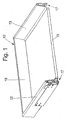
- FIG. 1 the front panel of the drawer 10 is not shown.
- the drawer 10 consists of the bottom 11, the two side frames 12, 13 and the rear wall 15.
- the side frames 12, 13 consist of hollow body sections and the bottom 11 is firmly connected thereto.
- the frames or the drawer with rails 23 are detachably connected. They follow the retraction and extension movement of the drawer 10.
- the rails 23 are coupled in a manner not shown with two lateral pull-out guides, wherein at least one further guide rail is fixedly arranged on the furniture body.
- each side frame 12, 13 an adapter is inserted.
- the adapter carries a carrier holder inserted into the front panel holder, preferably latching inserted, which are attached to the front panel.
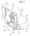
- the connection between the carrier holders 14 and the rails is effected by a respective coupling device 17, which in the Figures 2 and 3 is shown in more detail.
- FIG. 2 shows that the carrier holder 14 is inserted into the adapter 16.
- the front panel holder for aligning the front panel is equipped with two adjustment screws 18.
- the coupling device 17 consists of a clutch outer 19 and a clutch inner 20.
- the coupling outer part 19 equipped with a Einsteckzapfen 21 ( FIG. 10 ), which is inserted and secured in the end region of the running rail.
- the clutch outer part 19 has a relative to the end face of the running rail 23 projecting hollow body portion 24, which in the illustrated embodiment in the basic cross section is a square tube. How the particular FIG. 2 shows, the lower surface of the hollow body portion 24 is stepped down, so that a stop surface 25 is formed for the clutch inner 20.
- the clutch outer 19 is also provided on the upper side with a guide slot 26 which widens to the opening of the hollow body portion 24.
- the guide rail 23 is provided on the upper side with a square opening 27 into which a resilient latching tongue 28 of the support holder 14 engages.
- the drawer 10 is fixed or secured in the pull-out direction and in the insertion direction.
- the drawer 10 is secured in the vertical direction by the coupling device 17.
- the clutch inner 20 forms in the execution of the Figures 2 and 3 with the carrier holder 14 a one-piece plastic molding.
- the clutch inner part 20 extends approximately over the height of the bottom 11.
- the clutch inner part 20 is further stepped, in the illustrated embodiment, the clutch inner 20 consists of two end pieces 29, 30 and a central part 31.
- the upper, the support holder 14 facing end piece 30 has a the smallest distance of the two guide slots 26 limiting webs so that it can be regarded as a guide element.
- That the carrier holder 14 facing away from tail 29 has a width which corresponds to the width of the interior of the hollow body portion 24, so that this tail can be regarded as a guide element.
- the guide rail 23 facing the surface of the end piece 29 abuts against the stop surface 25 when the clutch inner 20 is inserted into the clutch outer 19, wherein shortly before reaching the end position einklippst the latching tongue.
- the central part 31 is wedge-shaped, wherein the tip of the guide rail 23 is facing. The helix angles coincide or approximately match the helix angles of the guide slot 26.
- FIG. 3 shows the connection of the drawer 10 with the slide rail 23 via the coupling device 19.
- the figure shows that the carrier holder 14 facing end piece 30 engages in the guide slot 26 and that the opposite end piece 29 and the central part 31 within the interior of the hollow body portion 24 is located.
- the outer free end faces of the hollow body portion 24 and the clutch inner part 20 are aligned with each other.
- FIGS. 4 to 10 show that also the rear wall 15 associated end of the running rail 23 is equipped with an adapter 32. In contrast to the illustrated embodiment, one or more adapters may be disposed between the front and rear portions.
- the FIG. 2 also shows that the guide slot 26 is bounded by positioning, which lie inside and are formed on the open side as inclined surfaces 33.
- FIGS. 4 to 9 show that in the rear end region of the running rail 23, a hook 34 is provided to lock the drawer 10.
- the hook 34 is C-shaped.
- each carrier holder 14 is provided with a resilient latching tongue 28 which engages in the latched state with a nose in the opening 27.
- the latching tongue 28 is designed so that the drawer 10 relative to the running rail 23 in the extension direction is not displaced when the drawer 10 is locked. The locking in the other direction is effected by the coupling devices 17th
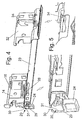
- FIGS. 4 and 5 show the drawer 10 in the locked state with the running rail 23.
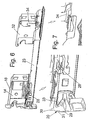
- Die FIGS. 6 and 7 show the drawer 10 in an intermediate position for removing the drawer 10 from the furniture body. In this position, the drawer 10 is pulled out by at least the thickness of the front panel of the furniture body. In this case, the drawer is moved a little bit by a corresponding manually applied force relative to the running rail upwards, in particular deforming the adjacent to the guide slot 26 areas of the hollow body portion 24.
- the latching tongue 28 is already pulled out of the opening 27, so that by further pulling out of the drawer 10 from the furniture body and further deformation of the hollow body portion 24 of the drawer 10 is disengaged from the running rail 23 and out of engagement with the two lateral rails 23rd comes, so that the drawer is free, as based on the FIG. 13 will be explained.
- the limited by the hook 34 bag is open to the front panel, so that the pulling out of the drawer 10 is not hindered.
- the insertion of the drawer 10 in the furniture body is done by placing on the rails 23 and insertion.
- FIG. 10 It is clear that the insertion pin 21 of the clutch outer part 19 is inserted into the running rail 23 closing and is secured by suitable measures. In addition, this figure shows how is secured by the hook 34 of the drawer 10 in the rear region, and that the latching tongue 28 engages lockingly into the opening 27.
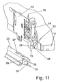
- the Figures 11 and 12 show the Figures 2 and 3 corresponding representations, but with the coupling outer part 19 on the carrier holder 14 and the clutch inner part 20 is therefore associated with the running rail 23.
- the outer coupling part is provided with the positive guide oblique surfaces 33, which in turn are assigned to the now underlying guide slot 26. This also reduces the distance to the opposite wall.
- the clutch inner part 20 is provided with corresponding oblique surfaces 36. The opposite web can be omitted since the lateral guidance within the clutch outer part 19 is given by the wedge-shaped design of the end piece 29.
- FIGS. 4 and 5 show the connected to the rails 23 drawer 10.
- the clutch inner part 20 strikes against the stop surface 25 of the clutch outer part 19.
- the narrower end piece 30 is stirred in the guide slot 26.
- the nose of the latching tongue 28 engages in the opening 27.
- the frames 12, 13 are pushed under the arranged in the rear region C-shaped hook 34.
- the hooks 34 are designed so that the frames 12, 13 do not touch the hooks 34 in the direction of insertion.
- FIGS. 6 and 7 show the first step of removing the drawer 10 from the furniture body.
- the hollow body portion 24 is elastically expanded by the central part 30 of the clutch inner part 20.
- the lower end piece 29 is in contact with the positive guide surfaces 33, so that the drawer 10 is additionally moved in the extension direction relative to the running rail 23.
- the locking lug 37 of the resilient latching tongue 28 has been pulled out of the opening 27, and lies with the free-swinging end on the Aushebekante of the drawer, so that jamming, snagging or damage to the latching tongue 28 can be excluded. It is advantageous by the solution described above, that the drawer 10 is secured, for example against jamming. Furthermore, the short Aushebeweg is very beneficial.
- FIGS. 8 and 9 show the next step to remove the drawer 10 from the furniture body. Thereafter, each of the rear wall 15 associated part of each frame 12, 13 has been pulled out of the region of the hook 34. The drawer 10 can then be completely pulled out of the furniture body. The drawer 10 slides with the rear area on the rails 23, so that damage to the hook 34 is effectively avoided when removing it from the furniture body and when inserting into the furniture body.
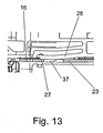
- FIG. 13 shows an enlarged view of a section of the carrier holder 13 in conjunction with the running rail 23.
- a detent 37 is formed on the resilient latching tongue 28 on the directed towards the central longitudinal axis of the running rail 23 side, which fully engages in the illustrated locked position in the opening 27 .
- the resilient latching tongue 28 is stepped at an end region, preferably at the end region facing the front panel, this area resting on the running rail.
- the edge formed by the step-shaped design lies in front of a lifting edge of the metallic adapter. As the FIG. 13 clearly shows, the step-shaped end portion associated edge of the locking lug 37 is at a relatively small distance to the edge bounding the opening.
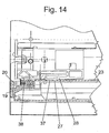
- a damping element 38 for example made of an elastic plastic or in the form of a spring or the like, is attached to the clutch outer part 19. This damping element 38 is opposite to a contact surface of the clutch inner part 20.
- the invention is not limited to the illustrated embodiment. It is essential that in each rail 23 on the front panel facing side, a plug or the coupling outer part 19 is used, which has a hollow body portion 24, in the interior of the clutch inner part 20 is inserted in the locked state, and that for removing the drawer 10 of this Hollow body portion 24 by acting on the drawer forces can be separated by the clutch inner 20 without damage from the clutch outer 19.
Landscapes
- Drawers Of Furniture (AREA)
Claims (15)
- Tiroir (10) avec un fond de tiroir (11), un panneau avant et une paroi arrière (15) opposée au panneau avant, avec deux châssis (12, 13) latéraux réalisés comme sections de corps creux, s'étendant dans le sens mobile du tiroir (10), qui sont pourvus au moins dans les zones d'extrémité, d'adaptateurs (16, 32), des porte-supports (14) étant fixés sur les adaptateurs côté avant (16), lesquels porte-supports sont reliés par encliquetage aux rails de roulement (23), caractérisé en ce qu'au moins un ou chaque encliquetage côté avant est formé entre le porte-support (14) et le rail de roulement (23) d'un dispositif de couplage (17), se composant d'une partie extérieure de couplage (19) et d'une partie intérieure de couplage (20) pouvant être insérée dedans, qui bloque dans le sens vertical à l'état encliqueté le tiroir (10) et une languette d'encliquetage (28) à ressort, s'engageant dans une ouverture (27) du rail de roulement (23), laquelle fixe ou bloque le tiroir (10) dans le sens d'extraction et dans le sens d'insertion.
- Tiroir selon la revendication 1, caractérisé en ce que chaque partie extérieure de couplage (19) est insérée fixement dans la zone d'extrémité du rail de roulement (23) et la partie intérieure de couplage (20) est formée ou placée d'un seul tenant sur le porte-support (14) fixé sur l'adaptateur (16) ou en ce que chaque partie extérieure de couplage (19) est agencée sur le porte-support (14) et la partie intérieure de couplage (20) est insérée dans la zone d'extrémité du rail de roulement (23), la partie extérieure de couplage (19) formant avec le porte-support (14) une pièce moulée d'un seul tenant.
- Tiroir selon l'une quelconque des revendications précédentes, caractérisé en ce que la languette d'encliquetage (28) s'étendant dans le sens longitudinal du rail de roulement (23) est formée sur chaque porte-support (14), laquelle présente sur le côté tourné vers l'axe médian longitudinal du rail de roulement un nez d'encliquetage (37) qui peut s'engager dans une ouverture (27) du rail de roulement (23) dans la position encliquetée.
- Tiroir selon l'une quelconque des revendications précédentes, caractérisé en ce qu'une zone d'extrémité de la languette d'encliquetage (28), de préférence la zone d'extrémité tournée vers le panneau avant est décalée de manière étagée et repose dans la position encliquetée du porte-support (14) avec le rail de roulement (23) sur le bord délimitant l'ouverture (27) et en ce que la zone d'extrémité réalisée de manière étagée de la languette d'encliquetage (28) repose sur une arête de l'adaptateur métallique (16) de telle manière que lors du levage du tiroir (10), la languette d'encliquetage (28) puisse être levée et que par l'extraction forcée du tiroir (10), le nez d'encliquetage (37) de la languette d'encliquetage (28) puisse être déplacé hors de l'ouverture (27).
- Tiroir selon l'une ou plusieurs quelconques des revendications précédentes, caractérisé en ce que la partie extérieure de couplage (19) est réalisée comme un bouchon et présente une section de corps creux (24) dépassant par rapport à la surface frontale du rail de roulement (23) et une fente de guidage (26) s'étendant dans le sens longitudinal du rail de roulement (23) pour la partie intérieure de couplage (20) s'engageant dans la section de corps creux (24) de la partie extérieure de couplage (19), laquelle partie intérieure de couplage s'élargit en direction du côté ouvert de la section de corps creux (24).
- Tiroir selon l'une quelconque des revendications précédentes, caractérisé en ce que la section de corps creux (24) de la partie extérieure de couplage (19) est décalée côté intérieur de manière étagée, la zone relevée se trouvant éloignée du côté ouvert de la section de corps creux (24) pour la formation d'une surface de butée (25) pour la partie intérieure de couplage (20).
- Tiroir selon l'une quelconque des revendications précédentes, caractérisé en ce qu'au moins la section de corps creux (24) de la partie extérieure de couplage (19) est équipée côté intérieur de surfaces obliques à guidage forcé (33).
- Tiroir selon l'une quelconque des revendications précédentes, caractérisé en ce que la partie intérieure de couplage (20) est conçue comme un coulisseau et est décalée de manière étagée à plusieurs reprises, vu dans le sens longitudinal du rail de roulement (23), et se compose de deux étages d'extrémité (29, 30) et d'un étage médian ou d'une partie médiane (31).
- Tiroir selon l'une quelconque des revendications précédentes, caractérisé en ce que la pièce d'extrémité (30) tournée ou éloignée du porte-support (14) s'engage dans la fente de guidage (26) de la section de corps creux (24) et en ce que la pièce d'extrémité (29) opposée s'engage dans l'espace intérieur de la section de corps creux (24).
- Tiroir selon l'une quelconque des revendications précédentes, caractérisé en ce que la partie médiane (31) ou l'étage médian de la partie intérieure de couplage (20) est conçue en forme de coin, la pointe se trouvant éloignée de l'ouverture de la section de corps creux (24) de la partie extérieure de couplage (19) et en ce que l'angle de chanfrein de la pièce médiane (31) de la partie intérieure de couplage (20) concorde ou concorde approximativement avec l'angle de chanfrein de la fente de guidage (26).
- Tiroir selon l'une quelconque des revendications précédentes, caractérisé en ce que les surfaces obliques à guidage forcé (33) s'étendent sur la profondeur entière ou sur une zone tournée vers le côté ouvert de la section de profilé creux (24) de la partie extérieure de couplage (19).
- Tiroir selon l'une quelconque des revendications précédentes, caractérisé en ce que la partie intérieure de couplage (20) est pourvue de surfaces obliques (36) correspondant aux surfaces à guidage forcé (33) de la partie extérieure de couplage (19).
- Tiroir selon l'une quelconque des revendications précédentes, caractérisé en ce que le tiroir (10) est l'élément d'actionnement pour un ou pour chaque dispositif de couplage (17) de sorte que lors du retrait du tiroir (10) hors du corps de meuble, une force verticale dirigée vers le haut agisse sur chaque dispositif de couplage (17) par le biais de la partie médiane (30) de la partie intérieure de couplage (20) sur la section creuse (24) de la partie extérieure de couplage.
- Tiroir selon l'une quelconque des revendications précédentes, caractérisé en ce que le tiroir (10) est bloqué dans la zone de la paroi arrière par des crochets (34) agencés sur le rail de roulement (23), de préférence des crochets conçus en C.
- Tiroir selon l'une quelconque des revendications précédentes, caractérisé en ce qu'au moins un élément d'amortissement (38) est agencé sur des surfaces frontales ou surfaces de contact opposées de la partie intérieure de couplage (20) et de la partie extérieure de couplage (19).
Applications Claiming Priority (3)
| Application Number | Priority Date | Filing Date | Title |
|---|---|---|---|
| DE202006014020 | 2006-09-08 | ||
| DE202007001782U DE202007001782U1 (de) | 2006-09-08 | 2007-02-02 | Schubkasten |
| PCT/EP2007/058733 WO2008028809A1 (fr) | 2006-09-08 | 2007-08-22 | Tiroir |
Publications (2)
| Publication Number | Publication Date |
|---|---|
| EP2059148A1 EP2059148A1 (fr) | 2009-05-20 |
| EP2059148B1 true EP2059148B1 (fr) | 2015-03-04 |
Family
ID=38922507
Family Applications (1)
| Application Number | Title | Priority Date | Filing Date |
|---|---|---|---|
| EP07802805.7A Active EP2059148B1 (fr) | 2006-09-08 | 2007-08-22 | Tiroir |
Country Status (9)
| Country | Link |
|---|---|
| EP (1) | EP2059148B1 (fr) |
| JP (1) | JP5309329B2 (fr) |
| KR (1) | KR101385629B1 (fr) |
| CN (1) | CN101511228B (fr) |
| AU (1) | AU2007293951B2 (fr) |
| DE (1) | DE202007001782U1 (fr) |
| RU (1) | RU2427303C2 (fr) |
| TW (1) | TW200836668A (fr) |
| WO (1) | WO2008028809A1 (fr) |
Families Citing this family (19)
| Publication number | Priority date | Publication date | Assignee | Title |
|---|---|---|---|---|
| DE202008000011U1 (de) * | 2008-02-22 | 2009-04-02 | Elco Kunststoffe Gmbh | Schub, Schublade o.dgl. |
| AT506879B1 (de) * | 2008-06-10 | 2011-07-15 | Blum Gmbh Julius | Vorrichtung zum lösbaren kuppeln einer schublade mit einer schiene einer schubladenausziehführung |
| DE202008008121U1 (de) * | 2008-06-19 | 2009-10-29 | Paul Hettich Gmbh & Co. Kg | Auszugsführung für Möbelauszugsteile |
| CN101543347B (zh) * | 2009-02-08 | 2011-08-31 | 伍志勇 | 滑轨与抽屉壁板的快速拆装机构 |
| DE202009013393U1 (de) * | 2009-10-21 | 2011-03-03 | Paul Hettich Gmbh & Co. Kg | Zargenhülle mit mindestens einem Zargenadapter |
| DE102010036582A1 (de) * | 2010-07-23 | 2012-07-12 | Paul Hettich Gmbh & Co. Kg | Rastmechanismus |
| AT510777B1 (de) * | 2010-11-23 | 2014-06-15 | Blum Gmbh Julius | Kupplungsvorrichtung für schubladen |
| ITMI20111629A1 (it) * | 2011-09-08 | 2013-03-09 | Salice Arturo Spa | Dispositivo per la stabilizzazione dell'accoppiamento fra un cassetto o simile ed una guida di estrazione, ed assieme almeno comprendente un cassetto o simile, una guida di estrazione ed un dispositvo per la stabilizzazione dell'accoppiamento fra il |
| CN103239037B (zh) * | 2012-02-14 | 2017-07-21 | 北京世博金属制品有限公司 | 用于抽屉上的抽帮与轨道的连接结构 |
| DE102015101006A1 (de) * | 2015-01-23 | 2016-07-28 | Paul Hettich Gmbh & Co. Kg | Auszugsführung, Set aus zwei Auszugsführungen, Möbel und Kraftfahrzeug mit mindestens einer Aufbewahrungseinrichtung |
| CN105054626B (zh) * | 2015-08-27 | 2017-06-16 | 伍志勇 | 家具抽屉与滑轨的稳固连接结构 |
| DE202015006943U1 (de) | 2015-10-05 | 2017-01-09 | Grass Gmbh | Vorrichtung zur lösbaren Verbindung eines in einem Möbelkorpus eines Möbelteils über eine Führungseinheit beweglich geführten Möbelauszugs mit der Führungseinheit |
| KR102611208B1 (ko) * | 2016-09-09 | 2023-12-08 | 김종원 | 가구 서랍용 풀아웃 가이드 |
| KR102646324B1 (ko) * | 2016-09-09 | 2024-03-08 | 김종원 | 가구 서랍용 풀아웃 가이드 |
| CN106343938A (zh) * | 2016-11-02 | 2017-01-25 | 佛山市顺德区美的洗涤电器制造有限公司 | 阻尼器组件及导轨组件及洗碗机 |
| DE102018108647A1 (de) * | 2018-04-11 | 2019-10-17 | Paul Hettich Gmbh & Co. Kg | Auszugsführung und Schubkastenserie |
| DE102018108646A1 (de) * | 2018-04-11 | 2019-10-17 | Paul Hettich Gmbh & Co. Kg | Vorrichtung zum Fixieren eines Schubelementes und Verfahren zur Montage und Demontage eines Schubelementes |
| AT526385B1 (de) * | 2022-07-21 | 2026-02-15 | Blum Gmbh Julius | Anordnung mit wenigstens einer Schubladenausziehführung |
| AT526396B1 (de) * | 2022-07-21 | 2024-10-15 | Blum Gmbh Julius | Schubladenseitenwand für eine Schublade |
Family Cites Families (7)
| Publication number | Priority date | Publication date | Assignee | Title |
|---|---|---|---|---|
| SU1639613A1 (ru) * | 1988-02-29 | 1991-04-07 | Украинский Государственный Институт По Проектированию Мебели И Столярных Изделий "Укргипромебель" Украинского Научно-Производственного Мебельного Объединения | Способ изготовлени щика |
| DE3942897A1 (de) * | 1989-12-23 | 1991-06-27 | Grass Ag | Schublade |
| DE9310582U1 (de) * | 1993-07-15 | 1993-09-23 | Paul Hettich GmbH & Co, 32278 Kirchlengern | Rasteinrichtung fuer schubkaesten o.dgl. |
| AT401715B (de) * | 1994-01-17 | 1996-11-25 | Blum Gmbh Julius | Differentialauszug für schubladen |
| CN2562640Y (zh) * | 2002-08-30 | 2003-07-30 | 李绍汉 | 活动轨与抽屉底部快装机构 |
| AT6773U1 (de) * | 2003-05-22 | 2004-04-26 | Blum Gmbh Julius | Vorrichtung zur befestigung einer frontblende an einer schublade |
| EP1483984B1 (fr) | 2003-06-05 | 2017-08-09 | Grass GmbH | Glissière pour tiroirs |
-
2007
- 2007-02-02 DE DE202007001782U patent/DE202007001782U1/de not_active Expired - Lifetime
- 2007-08-20 TW TW096130649A patent/TW200836668A/zh unknown
- 2007-08-22 AU AU2007293951A patent/AU2007293951B2/en not_active Ceased
- 2007-08-22 EP EP07802805.7A patent/EP2059148B1/fr active Active
- 2007-08-22 RU RU2009112282/12A patent/RU2427303C2/ru not_active IP Right Cessation
- 2007-08-22 KR KR1020097007149A patent/KR101385629B1/ko not_active Expired - Fee Related
- 2007-08-22 CN CN2007800332344A patent/CN101511228B/zh not_active Expired - Fee Related
- 2007-08-22 JP JP2009527101A patent/JP5309329B2/ja not_active Expired - Fee Related
- 2007-08-22 WO PCT/EP2007/058733 patent/WO2008028809A1/fr not_active Ceased
Also Published As
| Publication number | Publication date |
|---|---|
| WO2008028809A1 (fr) | 2008-03-13 |
| AU2007293951A1 (en) | 2008-03-13 |
| CN101511228A (zh) | 2009-08-19 |
| CN101511228B (zh) | 2011-12-21 |
| KR101385629B1 (ko) | 2014-04-16 |
| JP5309329B2 (ja) | 2013-10-09 |
| RU2427303C2 (ru) | 2011-08-27 |
| KR20090077045A (ko) | 2009-07-14 |
| DE202007001782U1 (de) | 2008-01-10 |
| AU2007293951B2 (en) | 2012-07-05 |
| RU2009112282A (ru) | 2010-10-20 |
| EP2059148A1 (fr) | 2009-05-20 |
| JP2010502329A (ja) | 2010-01-28 |
| TW200836668A (en) | 2008-09-16 |
Similar Documents
| Publication | Publication Date | Title |
|---|---|---|
| WO2008028809A1 (fr) | Tiroir | |
| EP2704605B1 (fr) | Glissière télescopique de tiroir | |
| EP0421458B1 (fr) | Tiroir | |
| EP2642897B1 (fr) | Dispositif d'accouplement pour tiroir | |
| EP3773073B1 (fr) | Rail de chargement pour une glissière télescopique de tiroir | |
| EP1881775B1 (fr) | Dispositif d'extraction telescopique | |
| EP1513429B1 (fr) | Ensemble pour relier un encadrement de tiroir au fond de tiroir | |
| AT518232B1 (de) | Schubladenanordnung | |
| DE202015105093U1 (de) | Ausziehsperrvorrichtung und Möbel | |
| WO2012110373A1 (fr) | Dispositif servant à verrouiller des pièces mobiles l'une par rapport à l'autre | |
| DE102010016594A1 (de) | Auszugsführung für Möbel oder Haushaltsgeräte | |
| EP3019046A1 (fr) | Glissière pour un tiroir | |
| EP2906077B1 (fr) | Dispositif d'éjection | |
| EP1318258B1 (fr) | Ferrure d'un vantail ou d'un dormant d'une fenêtre, d'une porte ou similaire | |
| EP3773074B1 (fr) | Systeme de tiroir comprenant un rail sur lequel differents types de tiroirs peuvent etre installes | |
| DE19828718A1 (de) | Rasteinrichtung zum lösbaren Befestigen von Schubkästen, Auszügen, Schüben o. dgl. an einer Führungsschiene | |
| EP2317047B1 (fr) | Agencement de ferrure | |
| EP3189749A1 (fr) | Guidage télescopique pour une partie de meuble mobile | |
| AT522739B1 (de) | Innenschubkasten und Möbel oder Haushaltsgerät | |
| EP0639687B1 (fr) | Glissière | |
| DE19849798A1 (de) | Auszugsführung mit Verriegelung | |
| EP3917360B1 (fr) | Dispositif pour fixer un tiroir et meuble | |
| CH693125A5 (de) | Ausziehvorrichtung für Hochschränke. | |
| DE20018104U1 (de) | Treibstangenverschluss |
Legal Events
| Date | Code | Title | Description |
|---|---|---|---|
| PUAI | Public reference made under article 153(3) epc to a published international application that has entered the european phase |
Free format text: ORIGINAL CODE: 0009012 |
|
| 17P | Request for examination filed |
Effective date: 20090323 |
|
| AK | Designated contracting states |
Kind code of ref document: A1 Designated state(s): AT BE BG CH CY CZ DE DK EE ES FI FR GB GR HU IE IS IT LI LT LU LV MC MT NL PL PT RO SE SI SK TR |
|
| AX | Request for extension of the european patent |
Extension state: AL BA HR MK RS |
|
| DAX | Request for extension of the european patent (deleted) | ||
| 17Q | First examination report despatched |
Effective date: 20121109 |
|
| GRAP | Despatch of communication of intention to grant a patent |
Free format text: ORIGINAL CODE: EPIDOSNIGR1 |
|
| INTG | Intention to grant announced |
Effective date: 20140925 |
|
| GRAS | Grant fee paid |
Free format text: ORIGINAL CODE: EPIDOSNIGR3 |
|
| GRAA | (expected) grant |
Free format text: ORIGINAL CODE: 0009210 |
|
| AK | Designated contracting states |
Kind code of ref document: B1 Designated state(s): AT BE BG CH CY CZ DE DK EE ES FI FR GB GR HU IE IS IT LI LT LU LV MC MT NL PL PT RO SE SI SK TR |
|
| REG | Reference to a national code |
Ref country code: GB Ref legal event code: FG4D Free format text: NOT ENGLISH |
|
| REG | Reference to a national code |
Ref country code: CH Ref legal event code: EP |
|
| REG | Reference to a national code |
Ref country code: IE Ref legal event code: FG4D Free format text: LANGUAGE OF EP DOCUMENT: GERMAN |
|
| REG | Reference to a national code |
Ref country code: AT Ref legal event code: REF Ref document number: 713024 Country of ref document: AT Kind code of ref document: T Effective date: 20150415 |
|
| REG | Reference to a national code |
Ref country code: DE Ref legal event code: R096 Ref document number: 502007013769 Country of ref document: DE Effective date: 20150423 |
|
| REG | Reference to a national code |
Ref country code: NL Ref legal event code: VDEP Effective date: 20150304 |
|
| PG25 | Lapsed in a contracting state [announced via postgrant information from national office to epo] |
Ref country code: FI Free format text: LAPSE BECAUSE OF FAILURE TO SUBMIT A TRANSLATION OF THE DESCRIPTION OR TO PAY THE FEE WITHIN THE PRESCRIBED TIME-LIMIT Effective date: 20150304 Ref country code: ES Free format text: LAPSE BECAUSE OF FAILURE TO SUBMIT A TRANSLATION OF THE DESCRIPTION OR TO PAY THE FEE WITHIN THE PRESCRIBED TIME-LIMIT Effective date: 20150304 Ref country code: SE Free format text: LAPSE BECAUSE OF FAILURE TO SUBMIT A TRANSLATION OF THE DESCRIPTION OR TO PAY THE FEE WITHIN THE PRESCRIBED TIME-LIMIT Effective date: 20150304 Ref country code: LT Free format text: LAPSE BECAUSE OF FAILURE TO SUBMIT A TRANSLATION OF THE DESCRIPTION OR TO PAY THE FEE WITHIN THE PRESCRIBED TIME-LIMIT Effective date: 20150304 |
|
| REG | Reference to a national code |
Ref country code: LT Ref legal event code: MG4D |
|
| PG25 | Lapsed in a contracting state [announced via postgrant information from national office to epo] |
Ref country code: LV Free format text: LAPSE BECAUSE OF FAILURE TO SUBMIT A TRANSLATION OF THE DESCRIPTION OR TO PAY THE FEE WITHIN THE PRESCRIBED TIME-LIMIT Effective date: 20150304 Ref country code: GR Free format text: LAPSE BECAUSE OF FAILURE TO SUBMIT A TRANSLATION OF THE DESCRIPTION OR TO PAY THE FEE WITHIN THE PRESCRIBED TIME-LIMIT Effective date: 20150605 |
|
| PG25 | Lapsed in a contracting state [announced via postgrant information from national office to epo] |
Ref country code: NL Free format text: LAPSE BECAUSE OF FAILURE TO SUBMIT A TRANSLATION OF THE DESCRIPTION OR TO PAY THE FEE WITHIN THE PRESCRIBED TIME-LIMIT Effective date: 20150304 |
|
| PG25 | Lapsed in a contracting state [announced via postgrant information from national office to epo] |
Ref country code: EE Free format text: LAPSE BECAUSE OF FAILURE TO SUBMIT A TRANSLATION OF THE DESCRIPTION OR TO PAY THE FEE WITHIN THE PRESCRIBED TIME-LIMIT Effective date: 20150304 Ref country code: CZ Free format text: LAPSE BECAUSE OF FAILURE TO SUBMIT A TRANSLATION OF THE DESCRIPTION OR TO PAY THE FEE WITHIN THE PRESCRIBED TIME-LIMIT Effective date: 20150304 Ref country code: SK Free format text: LAPSE BECAUSE OF FAILURE TO SUBMIT A TRANSLATION OF THE DESCRIPTION OR TO PAY THE FEE WITHIN THE PRESCRIBED TIME-LIMIT Effective date: 20150304 Ref country code: RO Free format text: LAPSE BECAUSE OF FAILURE TO SUBMIT A TRANSLATION OF THE DESCRIPTION OR TO PAY THE FEE WITHIN THE PRESCRIBED TIME-LIMIT Effective date: 20150304 Ref country code: PT Free format text: LAPSE BECAUSE OF FAILURE TO SUBMIT A TRANSLATION OF THE DESCRIPTION OR TO PAY THE FEE WITHIN THE PRESCRIBED TIME-LIMIT Effective date: 20150706 |
|
| PG25 | Lapsed in a contracting state [announced via postgrant information from national office to epo] |
Ref country code: IS Free format text: LAPSE BECAUSE OF FAILURE TO SUBMIT A TRANSLATION OF THE DESCRIPTION OR TO PAY THE FEE WITHIN THE PRESCRIBED TIME-LIMIT Effective date: 20150704 Ref country code: PL Free format text: LAPSE BECAUSE OF FAILURE TO SUBMIT A TRANSLATION OF THE DESCRIPTION OR TO PAY THE FEE WITHIN THE PRESCRIBED TIME-LIMIT Effective date: 20150304 |
|
| REG | Reference to a national code |
Ref country code: DE Ref legal event code: R097 Ref document number: 502007013769 Country of ref document: DE |
|
| PG25 | Lapsed in a contracting state [announced via postgrant information from national office to epo] |
Ref country code: IT Free format text: LAPSE BECAUSE OF FAILURE TO SUBMIT A TRANSLATION OF THE DESCRIPTION OR TO PAY THE FEE WITHIN THE PRESCRIBED TIME-LIMIT Effective date: 20150304 |
|
| PLBE | No opposition filed within time limit |
Free format text: ORIGINAL CODE: 0009261 |
|
| STAA | Information on the status of an ep patent application or granted ep patent |
Free format text: STATUS: NO OPPOSITION FILED WITHIN TIME LIMIT |
|
| PG25 | Lapsed in a contracting state [announced via postgrant information from national office to epo] |
Ref country code: DK Free format text: LAPSE BECAUSE OF FAILURE TO SUBMIT A TRANSLATION OF THE DESCRIPTION OR TO PAY THE FEE WITHIN THE PRESCRIBED TIME-LIMIT Effective date: 20150304 |
|
| 26N | No opposition filed |
Effective date: 20151207 |
|
| PG25 | Lapsed in a contracting state [announced via postgrant information from national office to epo] |
Ref country code: SI Free format text: LAPSE BECAUSE OF FAILURE TO SUBMIT A TRANSLATION OF THE DESCRIPTION OR TO PAY THE FEE WITHIN THE PRESCRIBED TIME-LIMIT Effective date: 20150304 |
|
| PG25 | Lapsed in a contracting state [announced via postgrant information from national office to epo] |
Ref country code: LU Free format text: LAPSE BECAUSE OF FAILURE TO SUBMIT A TRANSLATION OF THE DESCRIPTION OR TO PAY THE FEE WITHIN THE PRESCRIBED TIME-LIMIT Effective date: 20150822 Ref country code: MC Free format text: LAPSE BECAUSE OF FAILURE TO SUBMIT A TRANSLATION OF THE DESCRIPTION OR TO PAY THE FEE WITHIN THE PRESCRIBED TIME-LIMIT Effective date: 20150304 |
|
| REG | Reference to a national code |
Ref country code: CH Ref legal event code: PL |
|
| GBPC | Gb: european patent ceased through non-payment of renewal fee |
Effective date: 20150822 |
|
| PG25 | Lapsed in a contracting state [announced via postgrant information from national office to epo] |
Ref country code: LI Free format text: LAPSE BECAUSE OF NON-PAYMENT OF DUE FEES Effective date: 20150831 Ref country code: CH Free format text: LAPSE BECAUSE OF NON-PAYMENT OF DUE FEES Effective date: 20150831 |
|
| REG | Reference to a national code |
Ref country code: IE Ref legal event code: MM4A |
|
| REG | Reference to a national code |
Ref country code: FR Ref legal event code: ST Effective date: 20160429 |
|
| PG25 | Lapsed in a contracting state [announced via postgrant information from national office to epo] |
Ref country code: GB Free format text: LAPSE BECAUSE OF NON-PAYMENT OF DUE FEES Effective date: 20150822 Ref country code: IE Free format text: LAPSE BECAUSE OF NON-PAYMENT OF DUE FEES Effective date: 20150822 |
|
| PG25 | Lapsed in a contracting state [announced via postgrant information from national office to epo] |
Ref country code: FR Free format text: LAPSE BECAUSE OF NON-PAYMENT OF DUE FEES Effective date: 20150831 |
|
| REG | Reference to a national code |
Ref country code: DE Ref legal event code: R079 Ref document number: 502007013769 Country of ref document: DE Free format text: PREVIOUS MAIN CLASS: A47B0088040000 Ipc: A47B0088400000 |
|
| PG25 | Lapsed in a contracting state [announced via postgrant information from national office to epo] |
Ref country code: MT Free format text: LAPSE BECAUSE OF FAILURE TO SUBMIT A TRANSLATION OF THE DESCRIPTION OR TO PAY THE FEE WITHIN THE PRESCRIBED TIME-LIMIT Effective date: 20150304 |
|
| PG25 | Lapsed in a contracting state [announced via postgrant information from national office to epo] |
Ref country code: BG Free format text: LAPSE BECAUSE OF FAILURE TO SUBMIT A TRANSLATION OF THE DESCRIPTION OR TO PAY THE FEE WITHIN THE PRESCRIBED TIME-LIMIT Effective date: 20150304 Ref country code: HU Free format text: LAPSE BECAUSE OF FAILURE TO SUBMIT A TRANSLATION OF THE DESCRIPTION OR TO PAY THE FEE WITHIN THE PRESCRIBED TIME-LIMIT; INVALID AB INITIO Effective date: 20070822 |
|
| PG25 | Lapsed in a contracting state [announced via postgrant information from national office to epo] |
Ref country code: CY Free format text: LAPSE BECAUSE OF FAILURE TO SUBMIT A TRANSLATION OF THE DESCRIPTION OR TO PAY THE FEE WITHIN THE PRESCRIBED TIME-LIMIT Effective date: 20150304 |
|
| PG25 | Lapsed in a contracting state [announced via postgrant information from national office to epo] |
Ref country code: BE Free format text: LAPSE BECAUSE OF NON-PAYMENT OF DUE FEES Effective date: 20150831 |
|
| PG25 | Lapsed in a contracting state [announced via postgrant information from national office to epo] |
Ref country code: TR Free format text: LAPSE BECAUSE OF FAILURE TO SUBMIT A TRANSLATION OF THE DESCRIPTION OR TO PAY THE FEE WITHIN THE PRESCRIBED TIME-LIMIT Effective date: 20150304 |
|
| PGFP | Annual fee paid to national office [announced via postgrant information from national office to epo] |
Ref country code: AT Payment date: 20180821 Year of fee payment: 12 |
|
| REG | Reference to a national code |
Ref country code: AT Ref legal event code: MM01 Ref document number: 713024 Country of ref document: AT Kind code of ref document: T Effective date: 20190822 |
|
| PG25 | Lapsed in a contracting state [announced via postgrant information from national office to epo] |
Ref country code: AT Free format text: LAPSE BECAUSE OF NON-PAYMENT OF DUE FEES Effective date: 20190822 |
|
| P01 | Opt-out of the competence of the unified patent court (upc) registered |
Effective date: 20230407 |
|
| REG | Reference to a national code |
Ref country code: DE Ref legal event code: R084 Ref document number: 502007013769 Country of ref document: DE |
|
| PGFP | Annual fee paid to national office [announced via postgrant information from national office to epo] |
Ref country code: DE Payment date: 20250819 Year of fee payment: 19 |