EP1484496A1 - Chambre de poussée tubulaire d'un moteur de fusée avec un carter intégré - Google Patents
Chambre de poussée tubulaire d'un moteur de fusée avec un carter intégré Download PDFInfo
- Publication number
- EP1484496A1 EP1484496A1 EP04253281A EP04253281A EP1484496A1 EP 1484496 A1 EP1484496 A1 EP 1484496A1 EP 04253281 A EP04253281 A EP 04253281A EP 04253281 A EP04253281 A EP 04253281A EP 1484496 A1 EP1484496 A1 EP 1484496A1
- Authority
- EP
- European Patent Office
- Prior art keywords
- tubes
- jacket
- single piece
- combustion chamber
- manifold
- Prior art date
- Legal status (The legal status is an assumption and is not a legal conclusion. Google has not performed a legal analysis and makes no representation as to the accuracy of the status listed.)
- Granted
Links
- 238000002485 combustion reaction Methods 0.000 title claims abstract description 31
- 239000000463 material Substances 0.000 claims abstract description 29
- 238000010276 construction Methods 0.000 claims abstract description 26
- 238000000034 method Methods 0.000 claims abstract description 24
- 238000005219 brazing Methods 0.000 claims abstract description 23
- 239000011248 coating agent Substances 0.000 claims abstract description 19
- 238000000576 coating method Methods 0.000 claims abstract description 19
- 239000002826 coolant Substances 0.000 claims abstract description 10
- 238000005304 joining Methods 0.000 claims description 8
- 238000003466 welding Methods 0.000 claims description 8
- 238000009713 electroplating Methods 0.000 claims description 2
- 238000010290 vacuum plasma spraying Methods 0.000 claims description 2
- 238000007689 inspection Methods 0.000 description 7
- 239000010410 layer Substances 0.000 description 7
- PXHVJJICTQNCMI-UHFFFAOYSA-N Nickel Chemical compound [Ni] PXHVJJICTQNCMI-UHFFFAOYSA-N 0.000 description 6
- 229910045601 alloy Inorganic materials 0.000 description 4
- 239000000956 alloy Substances 0.000 description 4
- 239000000446 fuel Substances 0.000 description 4
- 239000003380 propellant Substances 0.000 description 4
- 239000010959 steel Substances 0.000 description 4
- 230000001419 dependent effect Effects 0.000 description 3
- 239000007800 oxidant agent Substances 0.000 description 3
- 229910000851 Alloy steel Inorganic materials 0.000 description 2
- 229910000990 Ni alloy Inorganic materials 0.000 description 2
- 229910000831 Steel Inorganic materials 0.000 description 2
- 230000001133 acceleration Effects 0.000 description 2
- 230000000712 assembly Effects 0.000 description 2
- 238000000429 assembly Methods 0.000 description 2
- 239000011247 coating layer Substances 0.000 description 2
- 230000006835 compression Effects 0.000 description 2
- 238000007906 compression Methods 0.000 description 2
- 238000002844 melting Methods 0.000 description 2
- 238000012986 modification Methods 0.000 description 2
- 230000004048 modification Effects 0.000 description 2
- 229910052759 nickel Inorganic materials 0.000 description 2
- 230000001172 regenerating effect Effects 0.000 description 2
- 239000002918 waste heat Substances 0.000 description 2
- RYGMFSIKBFXOCR-UHFFFAOYSA-N Copper Chemical compound [Cu] RYGMFSIKBFXOCR-UHFFFAOYSA-N 0.000 description 1
- 229910000881 Cu alloy Inorganic materials 0.000 description 1
- 150000001875 compounds Chemical class 0.000 description 1
- 238000001816 cooling Methods 0.000 description 1
- 229910052802 copper Inorganic materials 0.000 description 1
- 239000010949 copper Substances 0.000 description 1
- 238000009826 distribution Methods 0.000 description 1
- 239000011888 foil Substances 0.000 description 1
- 239000007789 gas Substances 0.000 description 1
- 230000012010 growth Effects 0.000 description 1
- 238000003780 insertion Methods 0.000 description 1
- 230000037431 insertion Effects 0.000 description 1
- 238000009434 installation Methods 0.000 description 1
- 239000007788 liquid Substances 0.000 description 1
- 238000003754 machining Methods 0.000 description 1
- 238000012545 processing Methods 0.000 description 1
- 239000000565 sealant Substances 0.000 description 1
- 238000007789 sealing Methods 0.000 description 1
- 238000012546 transfer Methods 0.000 description 1
- 238000005406 washing Methods 0.000 description 1
Images


Classifications
-
- F—MECHANICAL ENGINEERING; LIGHTING; HEATING; WEAPONS; BLASTING
- F02—COMBUSTION ENGINES; HOT-GAS OR COMBUSTION-PRODUCT ENGINE PLANTS
- F02K—JET-PROPULSION PLANTS
- F02K9/00—Rocket-engine plants, i.e. plants carrying both fuel and oxidant therefor; Control thereof
- F02K9/42—Rocket-engine plants, i.e. plants carrying both fuel and oxidant therefor; Control thereof using liquid or gaseous propellants
- F02K9/60—Constructional parts; Details not otherwise provided for
- F02K9/62—Combustion or thrust chambers
- F02K9/64—Combustion or thrust chambers having cooling arrangements
-
- Y—GENERAL TAGGING OF NEW TECHNOLOGICAL DEVELOPMENTS; GENERAL TAGGING OF CROSS-SECTIONAL TECHNOLOGIES SPANNING OVER SEVERAL SECTIONS OF THE IPC; TECHNICAL SUBJECTS COVERED BY FORMER USPC CROSS-REFERENCE ART COLLECTIONS [XRACs] AND DIGESTS
- Y10—TECHNICAL SUBJECTS COVERED BY FORMER USPC
- Y10T—TECHNICAL SUBJECTS COVERED BY FORMER US CLASSIFICATION
- Y10T29/00—Metal working
- Y10T29/49—Method of mechanical manufacture
- Y10T29/49346—Rocket or jet device making
Definitions
- the present invention relates to rocket engines and, more particularly to a tubular rocket engine combustion chamber.
- the rocket engine combustion chamber contains the combustion of pressurized fuel and oxidizer and the smooth acceleration of the combustion products to produce thrust.
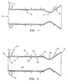
- the oxidizer and fuel are introduced under pressure through the injector 10, such as that shown in FIG. 1, attached to the top of the chamber.
- the combustion products under pressure advance to a de Laval nozzle 12, where the internal profile converges to a throat 14.
- the convergent throat section is immediately followed by a divergent section 16.
- the combustion products are then further accelerated to many times the speed of sound depending on the profile of the divergent section, the oxidizer and fuel combination, the pressure of the combustion products and the external pressure.
- the acceleration of gases creates thrust for the rocket engine.
- Regenerative cooled combustion chambers take part of the flow of cryogenic liquid propellant, usually fuel, to cool the walls of the combustion chamber.
- the coolant flows along the outside of the chamber through passages or tubes.
- the coolant recycles the waste heat to increase energy in the coolant. This increase energy in the coolant improves the efficiency of the cycle.
- Regenerative cooled combustion chambers for rocket engines typically fall into three categories: milled channel, platelet, and tubular construction.
- grooves of varying cross section are cut into the exterior of a liner, which assumes the shape of a de Laval nozzle.
- a jacket is built up over the open channels or a cylindrical piece is slid on and vacuum compression brazed to the liner. The jacket resists the coolant pressure only.
- a platelet construction is similar to a milled channel but divides the length of the liner into many smaller sections, which are then bonded together. A multiple piece jacket is then welded together over the liner and vacuum compression brazed together.
- a tubular combustion chamber stack formed tubes in the shape of a de Laval nozzle.
- the tubes contain the pressurized propellants for cooling the chamber walls and picking up waste heat to use in the cycle.
- the finished jacket assembly resists the pressure load of the combustion products only.
- a tubular construction combustion chamber can be manufactured in two ways depending on its size. If the chamber is large enough in diameter to allow access, the tubes and braze material can be laid directly into a single piece jacket and furnace brazed.
- Smaller chambers do not allow the use of a single piece jacket because access is limited to insert tubes inside a small diameter jacket.
- Assembly starts by stacking formed tubes on a mandrel in the shape of a de Laval nozzle.
- the tubes can be laid straight along the length of the mandrel or can be spiral wrapped around the mandrel.
- Braze wire, paste, or foil is inserted into all the cavities between the tubes.
- a multiple piece jacket is then added to the outside of the tubes.
- the jacket segments are then covered with overlapping strips between the jacket segments.
- the jackets and tubes are then furnace brazed together.
- the tubular construction chamber integrity depends on the quality of construction of the jacket and braze coverage for all joints between the tubes and the chamber manifolds and stiffening rings. Only X-ray or sonic inspection methods can accomplish inspection of the brazed tube to tube and jacket to tube joints. Repair of the brazed areas under the jacket is difficult. Failure of the combustion chamber can occur because inspection techniques were insufficient to identify areas of inadequate
- the tubular construction chamber yields the lightest and most efficient chamber due to the larger heat transfer area and lower stressed tube cross sections.
- the tubular construction chamber integrity depends on the quality of construction of the multiple piece jacket and braze coverage for all joints between the tubes, jacket segments, and manifolds.
- a method for forming a coolant system for a rocket engine combustion chamber broadly comprises the steps of providing a plurality of tubes formed and shaped into the profile of a nozzle with each of the tubes having a constantly expanding cross section in an upper chamber area, providing an inlet manifold and an exit manifold with a plurality of holes for receiving an end of each tube, inserting a brazing preform into each hole, inserting a first end of each tube into the inlet manifold and a second end of each tube into the outlet manifold so that the first end is surrounded by a first brazing preform and the second end is surrounded by a second brazing preform, and brazing the inlet and outlet manifolds to the tubes.
- the brazing step forms a series of brazed joints between the tubes and the manifolds.
- the method further includes the steps of forming a layer of coating material on exposed portions of the tubes and forming a single piece jacket construction around the tubes.
- the present invention also relates to a regeneratively cooled tubular construction rocket engine combustion chamber having a de Laval nozzle.
- the combustion chamber broadly comprises a plurality of tubes for conveying a coolant, each of the tubes being formed and shaped into the profile of the de Laval nozzle, an inlet manifold and an exit manifold, each of the tubes having a first end brazed to the inlet manifold and a second end brazed to the exit manifold, a layer of coating material on exposed portions of the tubes, and a single piece jacket construction surrounding the tubes and the layer of coating material and being joined to the tubes.
- the tubular construction chamber 20 consists of a set of tubes 22 formed and shaped into the profile of a de Laval nozzle.
- the tubes 22 feature a constantly expanding cross section in the upper chamber area 24 to provide a tapered inner wall 26.
- the expanding cross section refers to the inside cavity of the chamber 20 that the profile of the stack of tubes 22 creates.
- the profile of the tube 22 is farther away from the chamber centerline at the injector end of the chamber 20 than it is downstream. This forms a taper angle ⁇ of less than 1 degree.
- a tapered inner wall 26 improves removal of a mandrel (not shown) for tube bundle support during processing.
- the mandrel that supports the tubes 22 during brazing is inserted and removed through the injector end of the chamber 20. If the mandrel and tube profile were cylindrical, the mandrel would have to be dragged over the length of the tubes 22 for insertion or removal. This would subject the thin walled tubes 22 to possible damage.
- a tapered tube profile is supported by an identical tapered profile mandrel. Because of the taper, the mandrel does not touch the tube profile until the mandrel is fully inserted into the chamber. As the mandrel is removed, a gap is created between the tubes 22 and the mandrel. This gap increases as the mandrel is moved further out of the chamber. Once the mandrel is far enough away from the tubes 22, sections of the mandrel's circumference can be individually removed from inside the chamber.
- ferrules 28 may be brazed or welded to both ends of each tube 22 to create a tube assembly.
- Tubes 22 are typically made of steel based alloys, nickel based alloys or copper based alloys, depending upon the materials compatibility with the propellants used.
- the ferrules 28 can be steel or nickel based alloys depending upon the propellants used and the method of attachment to the tube materials.
- Each of the tubes or tube assemblies is inserted into a plurality of holes 29 in an exit manifold 30 and an inlet manifold 32.
- the tubes or tube assemblies are set up with braze preforms 31 inserted into manifold holes to achieve the desired coverage. As shown in FIG.
- the braze preforms 31 are helical coils of braze wire made to fit in the diameter of the manifold holes.
- the manifold holes are stepped to trap the braze perform 31 in place under the ferrules 28.
- the assembly is then furnace brazed.
- the brazing operation used is dependent upon the materials involved and the braze material chosen to join the parts together.
- each succeeding braze operation must be performed at a lower temperature than the previous braze operations in order to prevent re-melting those braze joints.
- braze operations are performed between 1400 F (760°C) and 2000 F (1093°C) with braze times for the gradual heat up and cool down of the parts dependent upon the mass of the parts involved.
- the coating material 34 can be any material that will create a bond with the tube materials. In general the material should be similar to the tube material so that differences in the thermal growths and modulus of elasticity of the two materials does not create additional stress on the bond. Materials can be steel, nickel, or copper alloys. Also the materials can be used together to form different layers in the coating.
- the layer of coating material 34 can either be vacuum plasma sprayed on, or electroplated onto, the tube surfaces using any suitable vacuum plasma spraying or electroplating techniques known in the art.
- the layer of coating material 34 provides sealing between the tubes 22, protects the tubes 22 from damage during assembly of the jacket, and after machining, provides a close tolerance surface to mate to the single piece jacket 36.
- Jacket sections 38 are then installed over the machined coating.
- the jacket sections 38 may be formed from any steel or nickel alloys that are compatible with the braze systems used and are compatible with welding and brazing. Braze wire can be installed in circumferential grooves 40 on the inside of each jacket section 38.
- the throat jacket section 38' consists of two 180 degree circumferential segments 38a and 38b.
- the jacket sections 38a and 38b are joined together, such as by welding, and to the inlet and exit manifolds 32 and 30 respectively, also such as by welding, to achieve a single piece jacket construction 36.
- the single piece jacket construction 36 is then brazed to the coated tube bundle.
- the jacket sections 38 are welded together and then they are welded to the exit and inlet manifolds 30 and 32, respectively, to form an air tight gap between the jacket sections and the coating over the tubes 22.
- Braze material may be plated onto the inner surface of the jacket sections and the outer surface of the coating 34 over the tubes 22.
- Several ports are installed in the jacket sections to allow a vacuum to pull the two surfaces together in intimate contact during the braze cycle. This brazing operation will be the lowest temperature braze used in the construction of the chamber 20 in order to prevent re-melting previously brazed joints.
- the braze times for the gradual heat up and cool down of the parts are dependent upon the mass of the parts involved.
- An end cap 50 on the forward end is then joined to the exit manifold 30 and the single piece jacket 36. Any suitable joining technique such as welding may be used.
- the exit manifold closeout sections 52 are then joined to the single piece jacket 36.
- any suitable joining technique such as welding may be used.
- jacket sections include two 180 degree circumferential throat sections or halves 38a and 38b.
- FIG 7, through the throat region shows the two throat jacket halves 38a and 38b, the coating layer 34 over the tubes and the tubes 22.
- the oval tunnels 60 through the jackets at the weld joint 62 allow inspection of the welds and also provide distribution of the vacuum from the main jacket ports to the throat jacket and aft jacket areas during the furnace brazing operation for the joints between the jackets and the coating layer 34 over the tubes. After all welding, brazing, inspection, washing and baking operations are complete, the tunnels 60 may be filled with a compatible sealant compound to prevent leakage around the throat area.
Landscapes
- Engineering & Computer Science (AREA)
- Chemical & Material Sciences (AREA)
- Combustion & Propulsion (AREA)
- Mechanical Engineering (AREA)
- General Engineering & Computer Science (AREA)
- Heat-Exchange Devices With Radiators And Conduit Assemblies (AREA)
- Rigid Pipes And Flexible Pipes (AREA)
- Turbine Rotor Nozzle Sealing (AREA)
- Coating By Spraying Or Casting (AREA)
Applications Claiming Priority (2)
| Application Number | Priority Date | Filing Date | Title |
|---|---|---|---|
| US10/456,824 US7051513B2 (en) | 2003-06-06 | 2003-06-06 | Rocket engine tubular chamber with single piece jacket |
| US456824 | 2003-06-06 |
Publications (2)
| Publication Number | Publication Date |
|---|---|
| EP1484496A1 true EP1484496A1 (fr) | 2004-12-08 |
| EP1484496B1 EP1484496B1 (fr) | 2006-03-22 |
Family
ID=33159593
Family Applications (1)
| Application Number | Title | Priority Date | Filing Date |
|---|---|---|---|
| EP04253281A Expired - Lifetime EP1484496B1 (fr) | 2003-06-06 | 2004-06-02 | Chambre de poussée tubulaire d'un moteur de fusée avec un carter intégré |
Country Status (5)
| Country | Link |
|---|---|
| US (1) | US7051513B2 (fr) |
| EP (1) | EP1484496B1 (fr) |
| JP (1) | JP4000129B2 (fr) |
| DE (1) | DE602004000522T2 (fr) |
| RU (1) | RU2267634C1 (fr) |
Cited By (6)
| Publication number | Priority date | Publication date | Assignee | Title |
|---|---|---|---|---|
| EP2078578A1 (fr) * | 2008-01-10 | 2009-07-15 | Siemens Aktiengesellschaft | Soudage de trous, procédé de revêtement de tiges de soudage |
| CN102950351A (zh) * | 2012-11-02 | 2013-03-06 | 首都航天机械公司 | 过氧化氢推力室身部扩散钎焊制造方法 |
| CN111980809A (zh) * | 2020-08-31 | 2020-11-24 | 合肥中科重明科技有限公司 | 一种主动冷却发动机燃料切换装置及切换方法 |
| EP4192644A1 (fr) * | 2020-08-07 | 2023-06-14 | Fraunhofer-Gesellschaft zur Förderung der angewandten Forschung e.V. | Procédé de réalisation d'une couche, système de fabrication et pièce |
| CN117102603A (zh) * | 2022-05-17 | 2023-11-24 | 中国航发商用航空发动机有限责任公司 | 一种燃烧室头部转接段组件钎焊方法及组件 |
| CN117754101A (zh) * | 2023-12-21 | 2024-03-26 | 河北志成束源科技有限公司 | 一种气压扩散焊拉瓦尔喷管未焊合修补方法及工装 |
Families Citing this family (15)
| Publication number | Priority date | Publication date | Assignee | Title |
|---|---|---|---|---|
| DE10237381B4 (de) * | 2002-08-12 | 2005-06-23 | Eads Space Transportation Gmbh | Brennkammerstruktur und Verfahren zu deren Herstellung |
| US7213392B2 (en) * | 2003-06-10 | 2007-05-08 | United Technologies Corporation | Rocket engine combustion chamber |
| RU2352445C2 (ru) * | 2006-05-05 | 2009-04-20 | Открытое акционерное общество "НПО Энергомаш имени академика В.П. Глушко" | Способ изготовления блока критического сечения сопла камеры жидкостного ракетного двигателя |
| US20080264372A1 (en) * | 2007-03-19 | 2008-10-30 | Sisk David B | Two-stage ignition system |
| DE102008052331A1 (de) * | 2007-10-24 | 2009-06-10 | Denso Corp., Kariya-shi | Verdampfereinheit |
| RU2422665C2 (ru) * | 2008-12-17 | 2011-06-27 | Государственное образовательное учреждение высшего профессионального образования "Воронежский государственный технический университет" | Способ установки трубы |
| RU2391544C1 (ru) * | 2008-12-17 | 2010-06-10 | Государственное образовательное учреждение высшего профессионального образования "Воронежский государственный технический университет" | Камера жидкостного ракетного двигателя |
| RU2454305C2 (ru) * | 2010-07-01 | 2012-06-27 | Федеральное государственное унитарное предприятие "Государственный космический научно-производственный центр имени М.В. Хруничева" (ФГУП "ГКНПЦ им. М.В. Хруничева") | Способ изготовления сопла камеры сгорания жидкостного ракетного двигателя (жрд), содержащего наружную и внутреннюю оболочки |
| US8960525B2 (en) | 2013-01-31 | 2015-02-24 | General Electric Company | Brazing process and plate assembly |
| CN107076055B (zh) | 2014-09-25 | 2018-11-02 | 帕奇德科尼克斯有限责任公司 | 流体加压供给装置、系统以及方法 |
| RU2579296C1 (ru) * | 2015-03-24 | 2016-04-10 | Открытое акционерное общество "Конструкторское бюро химавтоматики" | Газовый тракт жрд |
| DE102015011958B4 (de) * | 2015-09-18 | 2024-02-01 | Arianegroup Gmbh | Schubdüse |
| RU182948U1 (ru) * | 2018-06-22 | 2018-09-06 | Федеральное государственное унитарное предприятие "Центральный институт авиационного моторостроения им. П.И. Баранова" | Коническая рубашка охлаждения |
| CN114571053B (zh) * | 2022-03-18 | 2023-12-12 | 北京航天动力研究所 | 一种钛合金真空扩散焊喷管及设计方法 |
| CN114734106B (zh) * | 2022-03-30 | 2024-06-04 | 西安航天发动机有限公司 | 一种内壁带小孔和喉部铜钢钎焊件的钎焊方法 |
Citations (6)
| Publication number | Priority date | Publication date | Assignee | Title |
|---|---|---|---|---|
| US3390986A (en) * | 1966-08-30 | 1968-07-02 | Carrier Corp | Method of making a brazing preform |
| US3460759A (en) * | 1967-03-07 | 1969-08-12 | Nasa | Combustion chamber |
| US3768256A (en) * | 1969-08-14 | 1973-10-30 | Messerschmitt Boelkow Blohm | Thrust gas generator having a combustion chamber and thrust nozzle regeneratively cooled by a liquid |
| US3897316A (en) * | 1972-05-17 | 1975-07-29 | Us Air Force | Method for manufacturing a composite wall for a regeneratively cooled thrust chamber of a liquid propellant rocket engine |
| WO1995029785A1 (fr) * | 1994-04-29 | 1995-11-09 | United Technologies Corporation | Fabrication de chambres de poussee a parois tubulaires pour moteurs de fusee, par injection de poudre laser |
| EP0697515A2 (fr) * | 1994-08-16 | 1996-02-21 | United Technologies Corporation | Chambre de poussée d'un moteur de fusée revêtu de tubes |
Family Cites Families (8)
| Publication number | Priority date | Publication date | Assignee | Title |
|---|---|---|---|---|
| DE3436419C2 (de) * | 1983-10-07 | 1990-11-15 | Yoshimichi Chigasaki Kanagawa Masuda | Verfahren zur Herstellung von Raketenbrennkammern |
| DE3535779C1 (en) * | 1985-10-07 | 1987-04-09 | Messerschmitt Boelkow Blohm | Arrangement for the cooling of rocket engine walls |
| JPH0659502B2 (ja) * | 1987-03-26 | 1994-08-10 | 宇宙科学研究所長 | ロケット用高圧燃焼器の燃焼室及びその製造方法 |
| DE4301041C1 (de) * | 1993-01-16 | 1994-04-28 | Deutsche Aerospace | Verfahren zur Herstellung einer fluidgekühlten Wand in Röhrchenverbundbauweise |
| US5832719A (en) * | 1995-12-18 | 1998-11-10 | United Technologies Corporation | Rocket thrust chamber |
| US6134782A (en) * | 1998-11-30 | 2000-10-24 | United Technologies Corporation | Method of forming a rocket thrust chamber |
| RU2158840C2 (ru) * | 1999-01-21 | 2000-11-10 | Открытое акционерное общество "НПО Энергомаш им. акад. В.П. Глушко" | Корпус камеры жидкостного ракетного двигателя |
| RU2158841C2 (ru) * | 1999-01-21 | 2000-11-10 | Открытое акционерное общество "НПО Энергомаш им. акад. В.П. Глушко" | Камера жидкостного ракетного двигателя и ее корпус |
-
2003
- 2003-06-06 US US10/456,824 patent/US7051513B2/en not_active Expired - Fee Related
-
2004
- 2004-06-02 EP EP04253281A patent/EP1484496B1/fr not_active Expired - Lifetime
- 2004-06-02 DE DE602004000522T patent/DE602004000522T2/de not_active Expired - Fee Related
- 2004-06-07 RU RU2004117179/06A patent/RU2267634C1/ru not_active IP Right Cessation
- 2004-06-07 JP JP2004168063A patent/JP4000129B2/ja not_active Expired - Fee Related
Patent Citations (6)
| Publication number | Priority date | Publication date | Assignee | Title |
|---|---|---|---|---|
| US3390986A (en) * | 1966-08-30 | 1968-07-02 | Carrier Corp | Method of making a brazing preform |
| US3460759A (en) * | 1967-03-07 | 1969-08-12 | Nasa | Combustion chamber |
| US3768256A (en) * | 1969-08-14 | 1973-10-30 | Messerschmitt Boelkow Blohm | Thrust gas generator having a combustion chamber and thrust nozzle regeneratively cooled by a liquid |
| US3897316A (en) * | 1972-05-17 | 1975-07-29 | Us Air Force | Method for manufacturing a composite wall for a regeneratively cooled thrust chamber of a liquid propellant rocket engine |
| WO1995029785A1 (fr) * | 1994-04-29 | 1995-11-09 | United Technologies Corporation | Fabrication de chambres de poussee a parois tubulaires pour moteurs de fusee, par injection de poudre laser |
| EP0697515A2 (fr) * | 1994-08-16 | 1996-02-21 | United Technologies Corporation | Chambre de poussée d'un moteur de fusée revêtu de tubes |
Cited By (9)
| Publication number | Priority date | Publication date | Assignee | Title |
|---|---|---|---|---|
| EP2078578A1 (fr) * | 2008-01-10 | 2009-07-15 | Siemens Aktiengesellschaft | Soudage de trous, procédé de revêtement de tiges de soudage |
| WO2009087189A3 (fr) * | 2008-01-10 | 2009-12-17 | Siemens Aktiengesellschaft | Brasage de trous, procédé de revêtement et baguettes de brasure |
| EP2241397A1 (fr) * | 2008-01-10 | 2010-10-20 | Siemens Aktiengesellschaft | Soudage de trous, procédé de revêtement de tiges de soudage |
| CN102950351A (zh) * | 2012-11-02 | 2013-03-06 | 首都航天机械公司 | 过氧化氢推力室身部扩散钎焊制造方法 |
| EP4192644A1 (fr) * | 2020-08-07 | 2023-06-14 | Fraunhofer-Gesellschaft zur Förderung der angewandten Forschung e.V. | Procédé de réalisation d'une couche, système de fabrication et pièce |
| CN111980809A (zh) * | 2020-08-31 | 2020-11-24 | 合肥中科重明科技有限公司 | 一种主动冷却发动机燃料切换装置及切换方法 |
| CN111980809B (zh) * | 2020-08-31 | 2021-07-09 | 合肥中科重明科技有限公司 | 一种主动冷却发动机燃料切换装置及切换方法 |
| CN117102603A (zh) * | 2022-05-17 | 2023-11-24 | 中国航发商用航空发动机有限责任公司 | 一种燃烧室头部转接段组件钎焊方法及组件 |
| CN117754101A (zh) * | 2023-12-21 | 2024-03-26 | 河北志成束源科技有限公司 | 一种气压扩散焊拉瓦尔喷管未焊合修补方法及工装 |
Also Published As
| Publication number | Publication date |
|---|---|
| DE602004000522T2 (de) | 2006-08-24 |
| US7051513B2 (en) | 2006-05-30 |
| RU2267634C1 (ru) | 2006-01-10 |
| US20040244360A1 (en) | 2004-12-09 |
| DE602004000522D1 (de) | 2006-05-11 |
| EP1484496B1 (fr) | 2006-03-22 |
| JP4000129B2 (ja) | 2007-10-31 |
| JP2004360702A (ja) | 2004-12-24 |
Similar Documents
| Publication | Publication Date | Title |
|---|---|---|
| US7051513B2 (en) | Rocket engine tubular chamber with single piece jacket | |
| US6688100B1 (en) | Combustion chamber having a multiple-piece liner and associated assembly method | |
| US6829884B2 (en) | Rocket engine combustion chamber having multiple conformal throat supports | |
| US20050056020A1 (en) | Tube cooled combustor | |
| EP1352169B1 (fr) | Element de moteur-fusee et procede de fabrication d'un element de moteur-fusee | |
| US5701670A (en) | Method of making rocket engine combustion chamber utilizing "slide in" port liner | |
| US7213392B2 (en) | Rocket engine combustion chamber | |
| US5386628A (en) | Method of making a diffusion bonded rocket chamber | |
| US5371945A (en) | Method of making a tubular combustion chamber construction | |
| US5375325A (en) | Method of making a rocket chamber construction | |
| US5477613A (en) | Method of simultaneously forming rocket thrust chamber cooling tubes | |
| EP0720876B1 (fr) | Fabrication de chambres de missiles | |
| Quentmeyer | Rocket combustion chamber life-enhancing design concepts | |
| US5473817A (en) | Method of making cooled rocket combustion chamber construction | |
| US6134782A (en) | Method of forming a rocket thrust chamber | |
| EP1352166B1 (fr) | Tuyere de sortie et son procede de production | |
| WO2008010748A1 (fr) | Procédé de fabrication d'une structure de paroi | |
| EP4382245A1 (fr) | Chambres de combustion fabriquées de manière additive, structures de collecteur et procédés d'additif hybride associés | |
| CN119630935A (zh) | 用于制造热交换器用的管道的方法 | |
| RU2352445C2 (ru) | Способ изготовления блока критического сечения сопла камеры жидкостного ракетного двигателя | |
| JP2000158240A (ja) | 異形の管群から推力室を製作する方法 |
Legal Events
| Date | Code | Title | Description |
|---|---|---|---|
| EUG | Se: european patent has lapsed | ||
| PUAI | Public reference made under article 153(3) epc to a published international application that has entered the european phase |
Free format text: ORIGINAL CODE: 0009012 |
|
| AK | Designated contracting states |
Kind code of ref document: A1 Designated state(s): AT BE BG CH CY CZ DE DK EE ES FI FR GB GR HU IE IT LI LU MC NL PL PT RO SE SI SK TR |
|
| AX | Request for extension of the european patent |
Extension state: AL HR LT LV MK |
|
| 17P | Request for examination filed |
Effective date: 20041108 |
|
| 17Q | First examination report despatched |
Effective date: 20050121 |
|
| AKX | Designation fees paid |
Designated state(s): BE DE FR SE |
|
| GRAP | Despatch of communication of intention to grant a patent |
Free format text: ORIGINAL CODE: EPIDOSNIGR1 |
|
| GRAS | Grant fee paid |
Free format text: ORIGINAL CODE: EPIDOSNIGR3 |
|
| GRAA | (expected) grant |
Free format text: ORIGINAL CODE: 0009210 |
|
| AK | Designated contracting states |
Kind code of ref document: B1 Designated state(s): BE DE FR SE |
|
| REF | Corresponds to: |
Ref document number: 602004000522 Country of ref document: DE Date of ref document: 20060511 Kind code of ref document: P |
|
| REG | Reference to a national code |
Ref country code: SE Ref legal event code: TRGR |
|
| PGFP | Annual fee paid to national office [announced via postgrant information from national office to epo] |
Ref country code: BE Payment date: 20060714 Year of fee payment: 3 |
|
| ET | Fr: translation filed | ||
| PLBE | No opposition filed within time limit |
Free format text: ORIGINAL CODE: 0009261 |
|
| STAA | Information on the status of an ep patent application or granted ep patent |
Free format text: STATUS: NO OPPOSITION FILED WITHIN TIME LIMIT |
|
| 26N | No opposition filed |
Effective date: 20061227 |
|
| BERE | Be: lapsed |
Owner name: *UNITED TECHNOLOGIES CORP. Effective date: 20070630 |
|
| EUG | Se: european patent has lapsed | ||
| PG25 | Lapsed in a contracting state [announced via postgrant information from national office to epo] |
Ref country code: BE Free format text: LAPSE BECAUSE OF NON-PAYMENT OF DUE FEES Effective date: 20070630 |
|
| PG25 | Lapsed in a contracting state [announced via postgrant information from national office to epo] |
Ref country code: SE Free format text: LAPSE BECAUSE OF NON-PAYMENT OF DUE FEES Effective date: 20070603 |
|
| PGFP | Annual fee paid to national office [announced via postgrant information from national office to epo] |
Ref country code: SE Payment date: 20060628 Year of fee payment: 3 |
|
| PGFP | Annual fee paid to national office [announced via postgrant information from national office to epo] |
Ref country code: FR Payment date: 20090605 Year of fee payment: 6 |
|
| PGFP | Annual fee paid to national office [announced via postgrant information from national office to epo] |
Ref country code: DE Payment date: 20090630 Year of fee payment: 6 |
|
| REG | Reference to a national code |
Ref country code: FR Ref legal event code: ST Effective date: 20110228 |
|
| PG25 | Lapsed in a contracting state [announced via postgrant information from national office to epo] |
Ref country code: DE Free format text: LAPSE BECAUSE OF NON-PAYMENT OF DUE FEES Effective date: 20110101 |
|
| PG25 | Lapsed in a contracting state [announced via postgrant information from national office to epo] |
Ref country code: FR Free format text: LAPSE BECAUSE OF NON-PAYMENT OF DUE FEES Effective date: 20100630 |