EP1484559A1 - Chauffe-eau du type a pompe a chaleur - Google Patents
Chauffe-eau du type a pompe a chaleur Download PDFInfo
- Publication number
- EP1484559A1 EP1484559A1 EP03734844A EP03734844A EP1484559A1 EP 1484559 A1 EP1484559 A1 EP 1484559A1 EP 03734844 A EP03734844 A EP 03734844A EP 03734844 A EP03734844 A EP 03734844A EP 1484559 A1 EP1484559 A1 EP 1484559A1
- Authority
- EP
- European Patent Office
- Prior art keywords
- hot water
- storage tank
- heat exchanger
- temperature
- heat pump
- Prior art date
- Legal status (The legal status is an assumption and is not a legal conclusion. Google has not performed a legal analysis and makes no representation as to the accuracy of the status listed.)
- Withdrawn
Links
Images


Classifications
-
- F—MECHANICAL ENGINEERING; LIGHTING; HEATING; WEAPONS; BLASTING
- F24—HEATING; RANGES; VENTILATING
- F24D—DOMESTIC- OR SPACE-HEATING SYSTEMS, e.g. CENTRAL HEATING SYSTEMS; DOMESTIC HOT-WATER SUPPLY SYSTEMS; ELEMENTS OR COMPONENTS THEREFOR
- F24D19/00—Details
- F24D19/10—Arrangement or mounting of control or safety devices
- F24D19/1006—Arrangement or mounting of control or safety devices for water heating systems
- F24D19/1051—Arrangement or mounting of control or safety devices for water heating systems for domestic hot water
- F24D19/1054—Arrangement or mounting of control or safety devices for water heating systems for domestic hot water the system uses a heat pump
-
- F—MECHANICAL ENGINEERING; LIGHTING; HEATING; WEAPONS; BLASTING
- F24—HEATING; RANGES; VENTILATING
- F24H—FLUID HEATERS, e.g. WATER OR AIR HEATERS, HAVING HEAT-GENERATING MEANS, e.g. HEAT PUMPS, IN GENERAL
- F24H15/00—Control of fluid heaters
- F24H15/10—Control of fluid heaters characterised by the purpose of the control
- F24H15/136—Defrosting or de-icing; Preventing freezing
-
- F—MECHANICAL ENGINEERING; LIGHTING; HEATING; WEAPONS; BLASTING
- F24—HEATING; RANGES; VENTILATING
- F24H—FLUID HEATERS, e.g. WATER OR AIR HEATERS, HAVING HEAT-GENERATING MEANS, e.g. HEAT PUMPS, IN GENERAL
- F24H15/00—Control of fluid heaters
- F24H15/20—Control of fluid heaters characterised by control inputs
- F24H15/212—Temperature of the water
- F24H15/215—Temperature of the water before heating
-
- F—MECHANICAL ENGINEERING; LIGHTING; HEATING; WEAPONS; BLASTING
- F24—HEATING; RANGES; VENTILATING
- F24H—FLUID HEATERS, e.g. WATER OR AIR HEATERS, HAVING HEAT-GENERATING MEANS, e.g. HEAT PUMPS, IN GENERAL
- F24H15/00—Control of fluid heaters
- F24H15/20—Control of fluid heaters characterised by control inputs
- F24H15/212—Temperature of the water
- F24H15/219—Temperature of the water after heating
-
- F—MECHANICAL ENGINEERING; LIGHTING; HEATING; WEAPONS; BLASTING
- F24—HEATING; RANGES; VENTILATING
- F24H—FLUID HEATERS, e.g. WATER OR AIR HEATERS, HAVING HEAT-GENERATING MEANS, e.g. HEAT PUMPS, IN GENERAL
- F24H15/00—Control of fluid heaters
- F24H15/20—Control of fluid heaters characterised by control inputs
- F24H15/258—Outdoor temperature
-
- F—MECHANICAL ENGINEERING; LIGHTING; HEATING; WEAPONS; BLASTING
- F24—HEATING; RANGES; VENTILATING
- F24H—FLUID HEATERS, e.g. WATER OR AIR HEATERS, HAVING HEAT-GENERATING MEANS, e.g. HEAT PUMPS, IN GENERAL
- F24H15/00—Control of fluid heaters
- F24H15/30—Control of fluid heaters characterised by control outputs; characterised by the components to be controlled
- F24H15/305—Control of valves
- F24H15/325—Control of valves of by-pass valves
-
- F—MECHANICAL ENGINEERING; LIGHTING; HEATING; WEAPONS; BLASTING
- F24—HEATING; RANGES; VENTILATING
- F24H—FLUID HEATERS, e.g. WATER OR AIR HEATERS, HAVING HEAT-GENERATING MEANS, e.g. HEAT PUMPS, IN GENERAL
- F24H15/00—Control of fluid heaters
- F24H15/30—Control of fluid heaters characterised by control outputs; characterised by the components to be controlled
- F24H15/335—Control of pumps, e.g. on-off control
-
- F—MECHANICAL ENGINEERING; LIGHTING; HEATING; WEAPONS; BLASTING
- F24—HEATING; RANGES; VENTILATING
- F24H—FLUID HEATERS, e.g. WATER OR AIR HEATERS, HAVING HEAT-GENERATING MEANS, e.g. HEAT PUMPS, IN GENERAL
- F24H15/00—Control of fluid heaters
- F24H15/30—Control of fluid heaters characterised by control outputs; characterised by the components to be controlled
- F24H15/375—Control of heat pumps
- F24H15/38—Control of compressors of heat pumps
-
- F—MECHANICAL ENGINEERING; LIGHTING; HEATING; WEAPONS; BLASTING
- F24—HEATING; RANGES; VENTILATING
- F24H—FLUID HEATERS, e.g. WATER OR AIR HEATERS, HAVING HEAT-GENERATING MEANS, e.g. HEAT PUMPS, IN GENERAL
- F24H15/00—Control of fluid heaters
- F24H15/30—Control of fluid heaters characterised by control outputs; characterised by the components to be controlled
- F24H15/375—Control of heat pumps
- F24H15/385—Control of expansion valves of heat pumps
-
- F—MECHANICAL ENGINEERING; LIGHTING; HEATING; WEAPONS; BLASTING
- F24—HEATING; RANGES; VENTILATING
- F24H—FLUID HEATERS, e.g. WATER OR AIR HEATERS, HAVING HEAT-GENERATING MEANS, e.g. HEAT PUMPS, IN GENERAL
- F24H15/00—Control of fluid heaters
- F24H15/40—Control of fluid heaters characterised by the type of controllers
- F24H15/414—Control of fluid heaters characterised by the type of controllers using electronic processing, e.g. computer-based
-
- F—MECHANICAL ENGINEERING; LIGHTING; HEATING; WEAPONS; BLASTING
- F24—HEATING; RANGES; VENTILATING
- F24H—FLUID HEATERS, e.g. WATER OR AIR HEATERS, HAVING HEAT-GENERATING MEANS, e.g. HEAT PUMPS, IN GENERAL
- F24H15/00—Control of fluid heaters
- F24H15/40—Control of fluid heaters characterised by the type of controllers
- F24H15/486—Control of fluid heaters characterised by the type of controllers using timers
-
- F—MECHANICAL ENGINEERING; LIGHTING; HEATING; WEAPONS; BLASTING
- F24—HEATING; RANGES; VENTILATING
- F24H—FLUID HEATERS, e.g. WATER OR AIR HEATERS, HAVING HEAT-GENERATING MEANS, e.g. HEAT PUMPS, IN GENERAL
- F24H4/00—Fluid heaters characterised by the use of heat pumps
- F24H4/02—Water heaters
- F24H4/04—Storage heaters
-
- F—MECHANICAL ENGINEERING; LIGHTING; HEATING; WEAPONS; BLASTING
- F25—REFRIGERATION OR COOLING; COMBINED HEATING AND REFRIGERATION SYSTEMS; HEAT PUMP SYSTEMS; MANUFACTURE OR STORAGE OF ICE; LIQUEFACTION SOLIDIFICATION OF GASES
- F25B—REFRIGERATION MACHINES, PLANTS OR SYSTEMS; COMBINED HEATING AND REFRIGERATION SYSTEMS; HEAT PUMP SYSTEMS
- F25B30/00—Heat pumps
- F25B30/02—Heat pumps of the compression type
-
- F—MECHANICAL ENGINEERING; LIGHTING; HEATING; WEAPONS; BLASTING
- F25—REFRIGERATION OR COOLING; COMBINED HEATING AND REFRIGERATION SYSTEMS; HEAT PUMP SYSTEMS; MANUFACTURE OR STORAGE OF ICE; LIQUEFACTION SOLIDIFICATION OF GASES
- F25B—REFRIGERATION MACHINES, PLANTS OR SYSTEMS; COMBINED HEATING AND REFRIGERATION SYSTEMS; HEAT PUMP SYSTEMS
- F25B40/00—Subcoolers, desuperheaters or superheaters
-
- F—MECHANICAL ENGINEERING; LIGHTING; HEATING; WEAPONS; BLASTING
- F25—REFRIGERATION OR COOLING; COMBINED HEATING AND REFRIGERATION SYSTEMS; HEAT PUMP SYSTEMS; MANUFACTURE OR STORAGE OF ICE; LIQUEFACTION SOLIDIFICATION OF GASES
- F25B—REFRIGERATION MACHINES, PLANTS OR SYSTEMS; COMBINED HEATING AND REFRIGERATION SYSTEMS; HEAT PUMP SYSTEMS
- F25B47/00—Arrangements for preventing or removing deposits or corrosion, not provided for in another subclass
- F25B47/02—Defrosting cycles
- F25B47/022—Defrosting cycles hot gas defrosting
-
- F—MECHANICAL ENGINEERING; LIGHTING; HEATING; WEAPONS; BLASTING
- F25—REFRIGERATION OR COOLING; COMBINED HEATING AND REFRIGERATION SYSTEMS; HEAT PUMP SYSTEMS; MANUFACTURE OR STORAGE OF ICE; LIQUEFACTION SOLIDIFICATION OF GASES
- F25B—REFRIGERATION MACHINES, PLANTS OR SYSTEMS; COMBINED HEATING AND REFRIGERATION SYSTEMS; HEAT PUMP SYSTEMS
- F25B2309/00—Gas cycle refrigeration machines
- F25B2309/06—Compression machines, plants or systems characterised by the refrigerant being carbon dioxide
- F25B2309/061—Compression machines, plants or systems characterised by the refrigerant being carbon dioxide with cycle highest pressure above the supercritical pressure
-
- F—MECHANICAL ENGINEERING; LIGHTING; HEATING; WEAPONS; BLASTING
- F25—REFRIGERATION OR COOLING; COMBINED HEATING AND REFRIGERATION SYSTEMS; HEAT PUMP SYSTEMS; MANUFACTURE OR STORAGE OF ICE; LIQUEFACTION SOLIDIFICATION OF GASES
- F25B—REFRIGERATION MACHINES, PLANTS OR SYSTEMS; COMBINED HEATING AND REFRIGERATION SYSTEMS; HEAT PUMP SYSTEMS
- F25B2339/00—Details of evaporators; Details of condensers
- F25B2339/04—Details of condensers
- F25B2339/047—Water-cooled condensers
-
- F—MECHANICAL ENGINEERING; LIGHTING; HEATING; WEAPONS; BLASTING
- F25—REFRIGERATION OR COOLING; COMBINED HEATING AND REFRIGERATION SYSTEMS; HEAT PUMP SYSTEMS; MANUFACTURE OR STORAGE OF ICE; LIQUEFACTION SOLIDIFICATION OF GASES
- F25B—REFRIGERATION MACHINES, PLANTS OR SYSTEMS; COMBINED HEATING AND REFRIGERATION SYSTEMS; HEAT PUMP SYSTEMS
- F25B2600/00—Control issues
- F25B2600/02—Compressor control
- F25B2600/025—Compressor control by controlling speed
- F25B2600/0253—Compressor control by controlling speed with variable speed
-
- F—MECHANICAL ENGINEERING; LIGHTING; HEATING; WEAPONS; BLASTING
- F25—REFRIGERATION OR COOLING; COMBINED HEATING AND REFRIGERATION SYSTEMS; HEAT PUMP SYSTEMS; MANUFACTURE OR STORAGE OF ICE; LIQUEFACTION SOLIDIFICATION OF GASES
- F25B—REFRIGERATION MACHINES, PLANTS OR SYSTEMS; COMBINED HEATING AND REFRIGERATION SYSTEMS; HEAT PUMP SYSTEMS
- F25B2600/00—Control issues
- F25B2600/25—Control of valves
- F25B2600/2501—Bypass valves
-
- F—MECHANICAL ENGINEERING; LIGHTING; HEATING; WEAPONS; BLASTING
- F25—REFRIGERATION OR COOLING; COMBINED HEATING AND REFRIGERATION SYSTEMS; HEAT PUMP SYSTEMS; MANUFACTURE OR STORAGE OF ICE; LIQUEFACTION SOLIDIFICATION OF GASES
- F25B—REFRIGERATION MACHINES, PLANTS OR SYSTEMS; COMBINED HEATING AND REFRIGERATION SYSTEMS; HEAT PUMP SYSTEMS
- F25B2700/00—Sensing or detecting of parameters; Sensors therefor
- F25B2700/21—Temperatures
- F25B2700/2106—Temperatures of fresh outdoor air
-
- F—MECHANICAL ENGINEERING; LIGHTING; HEATING; WEAPONS; BLASTING
- F25—REFRIGERATION OR COOLING; COMBINED HEATING AND REFRIGERATION SYSTEMS; HEAT PUMP SYSTEMS; MANUFACTURE OR STORAGE OF ICE; LIQUEFACTION SOLIDIFICATION OF GASES
- F25B—REFRIGERATION MACHINES, PLANTS OR SYSTEMS; COMBINED HEATING AND REFRIGERATION SYSTEMS; HEAT PUMP SYSTEMS
- F25B9/00—Compression machines, plants or systems, in which the refrigerant is air or other gas of low boiling point
- F25B9/002—Compression machines, plants or systems, in which the refrigerant is air or other gas of low boiling point characterised by the refrigerant
- F25B9/008—Compression machines, plants or systems, in which the refrigerant is air or other gas of low boiling point characterised by the refrigerant the refrigerant being carbon dioxide
-
- Y—GENERAL TAGGING OF NEW TECHNOLOGICAL DEVELOPMENTS; GENERAL TAGGING OF CROSS-SECTIONAL TECHNOLOGIES SPANNING OVER SEVERAL SECTIONS OF THE IPC; TECHNICAL SUBJECTS COVERED BY FORMER USPC CROSS-REFERENCE ART COLLECTIONS [XRACs] AND DIGESTS
- Y02—TECHNOLOGIES OR APPLICATIONS FOR MITIGATION OR ADAPTATION AGAINST CLIMATE CHANGE
- Y02B—CLIMATE CHANGE MITIGATION TECHNOLOGIES RELATED TO BUILDINGS, e.g. HOUSING, HOUSE APPLIANCES OR RELATED END-USER APPLICATIONS
- Y02B30/00—Energy efficient heating, ventilation or air conditioning [HVAC]
- Y02B30/70—Efficient control or regulation technologies, e.g. for control of refrigerant flow, motor or heating
Definitions
- This invention relates to a heat pump type hot water supply apparatus.
- the refrigerant cycle 72 includes a compressor 74 , a hot water supply heat exchanger (utilization side heat exchanger) 75 , an electric expansion valve 77 , and a heat source side heat exchanger (air heat exchanger) 78 which are all connected in the given order.
- the hot water supply cycle 71 includes a hot water storage tank (hot water supply tank) 70 and a circulating path 79 .
- a water circulation pump 80 and a heat exchanging path 81 are inserted in the circulating path 79 .
- the heat exchanging path 81 is formed by the utilization side heat exchanger (water heat exchanger) 75 .
- the air heat exchanger 78 functions also as an evaporator. Accordingly, in some cases where the outside air temperature is low, frost formation may occur on the air heat exchanger 78 , resulting in a drop in capacity. To cope with this, such a type of heat pump type hot water supply apparatus is able to perform a defrost operation for removing the frost. In other words, a defrost operation of supplying hot gas directly to the air heat exchanger 78 from the compressor 74 is carried out.
- a discharge pipe 82 of the compressor 74 and a refrigerant flow path 83 establishing connection between the electric expansion valve 77 and the air heat exchanger 78 are connected together by a defrost circuit 85 provided with a defrost valve 84 .
- the defrost valve 84 By placing the defrost valve 84 in the open state, hot gas from the compressor 74 is allowed to flow into the defrost circuit 85 , and the hot gas is then supplied directly to the air heat exchanger 78 through the defrost circuit 85 , whereby the frost on the air heat exchanger 78 is melted and removed. And, during the defrost operation, the water circulation pump 80 of the circulating path 79 is stopped.
- the water circulation pump 80 can be stopped during a defrost operation, so there is the possibility that water inside the circulating path 77 (water in pipes, the water heat exchanger or the like) freezes. If frozen, this becomes an obstacle to a boiling-up operation, and in the worst case, the circulating path 77 may be damaged.
- the water circulation pump 78 can be made active, but if activated, this causes low-temperature warm water to flow into the top part of the hot water storage tank 76 .
- the boiling-up capacity is being considerably low during the defrost operation, it is impossible to boil warm water to an initial temperature (a desired high temperature) during the defrost operation. This lowers the temperature of hot water which is supplied to a bathtub or the like from the hot water storage tank 76 . Therefore, the operating time of a subsequent boiling-up operation has to be extended, thereby increasing running-costs.
- an object of the present invention is to provide a heat pump type hot water supply apparatus capable of preventing the inside of the circulating path from freezing and in addition capable of reducing the time required for removing the frost and securing reliability.
- a heat pump type hot water supply apparatus of a first invention comprises a hot water storage tank 3 , a circulating path 12 coupled to the hot water storage tank 3 , and a heat exchanging path 14 inserted in the circulating path 12 , wherein: the heat pump type hot water supply apparatus is able to perform an operation in which the heat exchanging path 14 is so heated by a heat pump heating source as to boil low-temperature water let out from a lower part of the hot water storage tank 3 for forwarding to an upper part of the hot water storage tank 3 ; a refrigerant circulating circuit of the heat pump heating source is formed by a sequential connection of a compressor 25 , a water heat exchanger 26 for heating the low-temperature water, a pressure reducing mechanism 27 , and an air heat exchanger 28 ; and the refrigerant circulating circuit further comprises a defrost circuit 38 for supplying hot gas from the compressor 25 , to the air heat exchanger 28 .
- the heat pump type hot water supplying apparatus of the first invention is characterized in that it is able to perform a defrost operation for providing a supply of hot gas to the air heat exchanger 28 , with a water circulation pump 13 of the circulating path 12 held in abeyance, and that a defrost control means 20a is provided which activates the water circulation pump 13 if the defrost operation has been continued for not less than a predetermined time period since the start thereof.
- the heat pump type hot water supplying apparatus of the first invention it is possible to perform a defrost operation of supplying hot gas from the compressor 25 to the air heat exchanger 28 when frost formation occurs on the air heat exchanger 28 due to a drop in outside air temperature or the like, whereby the frost growing on the air heat exchanger 28 is melted and removed.
- the water circulation pump 13 is made active if the defrost operation has been continued for a predetermined time period with the water circulation pump 13 held in abeyance.
- Such arrangement makes it possible to avoid the situation that the water circulation pump 13 is held in abeyance over long periods.
- a heat pump type hot water supply apparatus of a second invention is characterized in that activation of the water circulation pump 13 during the defrost operation is carried out when the outside air temperature is not more than a predetermined low temperature.
- the heat pump type hot water supplying apparatus of the second invention it is arranged such that activation of the water circulation pump 13 during the defrost operation is carried out when the outside air temperature is not more than a predetermined low temperature.
- activation of the water circulation pump 13 during the defrost operation is carried out when the outside air temperature is not more than a predetermined low temperature.
- a heat pump type hot water supply apparatus of a third embodiment is characterized in that a bypass flow path 15 , branched off from a part of the circulating path 12 on the side of a hot water inlet opening 11 and connected to a lower part side of the hot water storage tank 3 , is provided so that warm water, delivered toward the hot water inlet opening 11 during activation of the water circulation pump 13 in the defrost operation, flows into a lower part of the hot water storage tank 3 through the bypass flow path 15.
- warm water delivered toward the hot water inlet opening 11 during activation of the water circulation pump in the defrost operation is bypassed to flow into the lower part of the hot water storage tank 3 through the bypass flow path 15, thereby preventing low-temperature warm water from entering the upper part of the hot water storage tank 3 .
- high-temperature hot water in the upper part of the hot water storage tank 3 is not mixed with low-temperature warm water, thereby preventing hot water to be supplied to a bathtub or the like from the upper part of the hot water storage tank 3 from falling in the temperature.
- a heat pump type hot water supply apparatus of a fourth invention is characterized in that a supercritical refrigerant for use in a supercritical state is employed as a refrigerant.
- the heat pump type hot water supplying apparatus of the fourth invention there is no trouble with ozone layer depletion and environmental contamination, and the heat pump type hot water supplying apparatus of the fourth invention is a global environment-friendly, heat pump type hot water supplying apparatus.
- the heat pump type hot water supplying apparatus of the first invention it is possible to perform a defrost operation in which hot gas from the compressor is supplied to the air heat exchanger if there occurs frost formation on the air heat exchanger due to a drop in outside air temperature.
- the frost on the air heat exchanger is melted and removed, thereby making it possible to perform a stable boiling-up operation without a drop in capacity.
- the water circulation pump is made active.
- the activation time is very short. Therefore, a large amount of low-temperature warm water will not flow into the upper part of the hot water storage tank. This prevents the hot water in the hot water storage tank from falling in the temperature after completion of the defrost operation, and an extension of the boiling-up operation time after the defrost operation is avoided, thereby making it possible to reduce running costs.
- the heat pump type hot water supplying apparatus of the fourth invention there is no trouble with ozone layer depletion and environmental contamination, and the heat pump type hot water supplying apparatus of the fourth invention is a global environment-friendly, heat pump type hot water supplying apparatus.
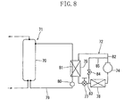
- the heat pump type hot water supply apparatus is comprised of a hot water supply cycle 1 and a refrigerant cycle 2 .
- the hot water supply cycle 1 includes a hot water storage tank 3 , wherein hot water stored in the hot water storage tank 3 is supplied to a bathtub (not shown in the figure) or the like. More specifically, the hot water storage tank 3 is provided, at its bottom wall portion, with a water supply opening 5 and is further provided, at its top wall portion, with a hot water supply opening 6 . And, tap water is supplied to the hot water storage tank 3 from the water supply opening 5 and high-temperature hot water is delivered outwardly from the hot water supply opening 6 .
- a water intake opening 10 is formed in a portion of the bottom wall and a hot water inlet opening 11 is formed in an upper portion of the side wall (peripheral wall), and the water intake opening 10 and the hot water inlet opening 11 are connected together by a circulating path 12 .
- a water circulation pump 13 and a heat exchanging path 14 are inserted in the circulating path 12 .
- a water supply flow path 8 is connected to the water supply opening 5 .
- a bypass flow path 15 is provided in the circulating path 12 .
- the bypass flow path 15 branches off from a part of the circulating path 12 on the side of the hot water intake opening 11 , and is connected to a lower part of the hot water storage tank 3 (a part of the bottom wall in this case).
- a first switching valve 17 inserted between a branch part 16 and the hot water inlet opening 11 is a first switching valve 17.
- a second switching valve 18 is inserted on the side of the branch part 16 of the bypass flow path 15 .
- the switching valves 17 and 18 constitute a bypass switching means 19 .
- Each of the switching valves 17 and 18 of the bypass switching means 19 is controlled by a control means 20 which will be described later.
- the first switching valve 17 of the bypass switching means 19 When: the first switching valve 17 of the bypass switching means 19 is placed in the open state; the second switching valve 18 is placed in the closed state; and the water circulation pump 13 is activated, warm water is let out from the water intake opening 10 and enters the circulating path 12. Then, the water flows through the heat exchanging path 14 . And, the water leaves the heat exchanging path 14 and flows into the upper part of the hot water storage tank 3 from the hot water inlet opening 11 .
- the state, in which water flows into the upper part of the hot water storage tank 3 through the hot water inlet opening 11 is called the "normal circulation state".
- the first switching valve 17 of the bypass switching means 19 is placed in the closed state; the second switching valve 18 is placed in the open state; and the water circulation pump 13 is activated, warm water flows outwardly and enters the circulating path 12 from the water intake opening 10 . Then, the water flows through the heat exchanging path 14 . And, the water leaves the heat exchanging path 14 , flows into the bypass flow path 15 through the branch part 16 , and flows into the lower part of the hot water storage tank 3 from the bypass flow path 15.
- the state, in which water flows into the lower part of the hot water storage tank 3 from the bypass flow path 15 is called the "bypass circulation state". In the bypass circulation state, warm water (low-temperature water) is not allowed to flow into the upper part of the hot water storage tank 3 .
- the circulating path 12 is provided with a pipe 21 on the side of the hot water supply cycle 1 and a pipe 22 on the side of the refrigerant cycle 2 , wherein the pipes 21 and 22 are connected by connection pipes 23 and 24 . Since the connection pipes 23 and 24 are laid outdoors, there is the possibility that the inside of the connection pipes 23 and 24 may freeze when the outside air temperature is low, as will be described later.
- the refrigerant cycle (heat pump type heating) 2 includes a refrigerant circulating circuit.
- the refrigerant circulating circuit is formed by a sequential connection of a compressor 25 , a water heat exchanger 26 which constitutes the heat exchanging path 14 , a pressure reducing mechanism (electric expansion valve) 27 , and an air heat exchanger 28 .
- a discharge pipe 29 of the compressor 25 is connected to the water heat exchanger 26 ; the water heat exchanger 26 and the electric expansion valve 27 are connected together by a refrigerant passage way 30 ; the electric expansion valve 27 and the air heat exchanger 28 are connected together by a refrigerant passage way 31 ; and the air heat exchanger 28 and the compressor 25 are connected together by a refrigerant passage way 33 in which is inserted an accumulator 32 .
- a supercritical refrigerant for example, carbon dioxide gas
- the air heat exchanger 28 is equipped with a fan 34 for controlling the capacity of the air heat exchanger 28 .
- the circulating path 12 is provided with an incoming water thermistor 35a operable to detect the temperature (incoming water temperature) of warm water (low-temperature water) which is let out from the water intake opening 10 and enters the heat exchanging path 14 and an outgoing hot water thermistor 36a operable to detect the temperature (outgoing hot water temperature) of warm water heated by the heat exchanging path 14 .
- the air heat exchanger 28 is further provided with an air heat exchanger thermistor 48a operable to detect the temperature of the air heat exchanger 28 .
- the heat pump type hot water supply apparatus of Figure 1 is provided with an outside air temperature detection thermistor 37a operable to detect the temperature of outside air.
- the discharge pipe 29 and the refrigerant passage way 31 are connected together by a defrost circuit 38 provided with a defrost valve 39 . More specifically, hot gas from the compressor 25 is supplied directly to the air heat exchanger 28 which functions as an evaporator, thereby making it possible to perform a defrost operation for removing the frost from on the evaporator 28.
- the refrigerant cycle 2 is able to perform a normal hot water boiling-up operation and a defrost operation.
- a bypass circuit 42 which branches off from the refrigerant circulating circuit on the high-pressure side and which merges into the refrigerant circulating circuit at a position downstream of the branch part.
- a refrigerant adjusting unit 43 is inserted in the bypass circuit 42 .
- an adjustment valve 44 for flow rate adjustment is provided on the outlet side of the refrigerant adjusting unit 43 .
- the bypass circuit 42 includes a first passage way 45 which branches off from upstream of the water heat exchanger 26 and which is connected to the refrigerant adjusting unit 43 , and a second passage way 46 which extends from the refrigerant adjusting unit 43 and which merges with the water heat exchanger 26 on the side downstream of the branch part of the first passage way 54 .
- the flow rate adjustment valve 44 is inserted in the second passage way 46 .
- a passage way 47 constituting a part of the refrigerant passage way 31 is arranged, wherein high-pressure refrigerant which has entered the refrigerant adjusting unit 43 through the bypass circuit 42 and low-pressure refrigerant flowing through the passage way 47 are subjected to heat exchange.
- the rate of flow of refrigerant passing through the inside of the refrigerant adjusting unit 43 is adjusted by controlling the valve opening of the adjustment valve 44 , and the temperature of refrigerant in the refrigerant adjusting unit 43 is controlled, the reason for which is as follows.
- the refrigerant temperature is maintained at a requested value, and the inside of the refrigerant adjusting unit 43 is made to hold an adequate amount of refrigerant, thereby optimizing the amount of refrigerant circulating in the circuit.
- the heat pump type hot water supply apparatus has a control part which is provided with an incoming water temperature detecting means 35 , an outgoing hot water temperature detecting means 36 , an outside air temperature detecting means 37 , an air heat exchanger temperature detecting means 48, a timer means 50, a control means 20, and other components (see Figure 2 ). Data from these detecting means 35, 36, 37, 48 and data from the timer means 50 are all fed to the control means 20. Based on the data, the control means 20 sends control signals to the compressor 25 , to the defrost valve 39 , and to other components. In response to the control signals, the compressor 25 and other components are activated.
- the incoming water temperature detecting means 35 is formed by the incoming water thermistor 35a .
- the outgoing hot water temperature detecting means 36 is formed by the outgoing hot water thermistor 36a .
- the outside air temperature detecting means 37 is formed by the outside air temperature detecting thermistor 37a .
- the air heat exchanger temperature detecting means 48 is formed by the air heat exchanger thermistor 48a .
- the timer means 50 is formed by an existing timer or the like capable of measuring time.
- the timer means 50 is provided with a timer TD0, a timer TD1, a timer TD2 et cetera.
- the control means 20 is formed by for example a microcomputer.
- the bypass switching means 19 when: the bypass switching means 19 is placed in the normal circulation state; the defrost valve 39 is placed in the closed state; the compressor 25 is activated; and the water circulation pump 13 is activated (operated), water (low-temperature water) stored in the hot water storage tank 3 is let out from the water intake opening (10) formed at the bottom part of the hot water storage tank 3 and flows through the heat exchanging path 14 of the circulating path 12 .
- the low-temperature water is heated (boiled up) by the water heat exchanger 26 and is forced to flow back or flow into the upper part of the hot water storage tank 3 from the hot water inlet opening 11.
- Such an operation is carried out continuously, thereby making it possible to store high-temperature hot water in the hot water storage tank 3 .
- the control means 20 makes it possible to conclude that the air heat exchanger 28 becomes frosted, when the boiling-up capacity falls to a predetermined low capacity or when the average of accumulated values of the boiling-up capacity found at predetermined intervals of time drops a given number of times consecutively.
- the boiling-up capacity when there is frost formation on the air heat exchanger 28 is lower than when there is no frost formation, and it is therefore possible to conclude that the air heat exchanger 28 becomes frosted if the boiling-up capacity falls down to a given low boiling-up capacity.
- This capacity (CAP) is found by the following mathematical expression (1).
- CAP KCAP x PSR x (DB - DTO) where:
- the incoming water temperature is detected by the incoming water thermistor 35a and the outgoing hot water temperature is detected by the outgoing hot water thermistor 36a .
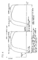
- the boiling-up capacity draws a wave form as shown in Figure 4 , and when the capacity falls down to a predetermined value, a defrost operation starts.
- the capacity index of the water circulation pump 13 pump command value, rotation number et cetera may be used in addition to the pump output and the pump capacity index is one proportional to the amount of water circulating through the water circulation pump 13 .
- the capacity is calculated at predetermined intervals of time (TSAMP: for example, for every ten seconds), and from a sum of the calculation results, an accumulated value average is obtained by the following mathematical expression (2).
- CAPAV is the average capacity.
- ⁇ CAP is the CAP (boiling-up capacity) accumulated value
- NSAMP is the number of times that accumulation is carried out.
- CAP boiling-up capacity
- a defrost operation is carried out.
- the defrost operation is started by supplying hot gas to the air heat exchanger 28 with the water circulation pump 13 held in abeyance.
- the defrost operation is carried out continuously for a long period of time, this produces the danger that the circulating path 12 (especially the inside of the connection pipes 23 and 24 arranged outdoors) freezes.
- a pipe antifreeze operation in which the water circulation pump 13 is activated, is carried out.
- the pipe antifreeze operation is controlled by a defrost control means 20a formed by the control means 20.
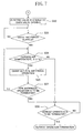
- Step S1 control steps for the start of a defrost operation in the heat pump type hot water supply apparatus.
- the bypass switching means 19 is placed in a state to start a boiling-up operation (i.e., the normal circulation state) and, in addition, the defrost valve 39 is placed in the closed state, and the compressor 25 starts operating (Step S1).
- Step S12 if an abnormality, such as no warm water in the hot water storage tank 3 , is detected, this requires execution of a process for dealing with the occurring abnormality (Step S12) so that the compressor 25 is stopped (Step S13) and, thereafter, that the defrost start prevention timer TD2 is reset.
- Step S2 After setting the compressor 25 in operation (Step S1), it is decided whether or not the boiling-up operation has been completed (Step S2). If decided that the boiling-up operation has been completed in Step S2, then the compressor 25 is stopped in Step S3 and each of the TD0, TD1, TD2 timers is reset and the boiling-up operation is terminated (completed).
- Step S4 it is decided whether or not the count time of TD1 (for example, 45 minutes) has elapsed and it is also decided whether or not the count time of TD2 (for example, 12 minutes) has elapsed. If decided that they have not yet elapsed, there is made a wait until TD0, TD1, and TD2 have elapsed (Step S10). On the other hand, if decided that they have elapsed, then the procedure moves to Step S5.
- TD0 is a defrost start decision switching boiling-up operation accumulation timer and its count time is for example 90 minutes.
- TD1 is a boiling-up operation accumulation timer and its count time is for example 45 minutes.
- Step S5 it is decided whether or not DE ⁇ DDEF1 (- 20 °C) holds.
- DE indicates the temperature of the air heat exchanger 28 detected by the air heat exchanger thermistor 48 and DDEF1 indicates the defrost start decision air heat exchanger temperature.
- DDEF1 is set to for example - 20 °C. In other words, if the temperature of the air heat exchanger 28 is lower than - 20 °C, then the procedure moves to Step S6 to perform a frost removing operation (defrost operation).
- Step S5 it is decided whether or not TD0 (for example, 90 minutes) has elapsed. If decided that TD0 has elapsed, then the procedure moves to Step S8. If not, then the procedure moves to Step S9.
- TD0 for example, 90 minutes
- Step S8 it is decided whether or not DE ⁇ DDE1 has held continuously for the count time of the TD3.
- DDE1 indicates the defrost start decision temperature (reference temperature), e.g., (outside air temperature - 9) °C.
- reference temperature e.g., (outside air temperature - 9) °C.
- TD3 is a defrost start determination continuation timer and is set to for example a period of 60 seconds.
- Step S8 If the condition is satisfied in Step S8, i.e., if the temperature of the air heat exchanger 28 falls below the reference temperature, then the procedure moves to Step S6. If not, then the procedure moves to Step S2 from Step S10.
- Step S9 the accumulated value average of the boiling-up capacity is found at predetermined intervals of time (for example, 10 seconds) with the condition of DE ⁇ DDE1 held, and it is decided whether or not the accumulated average value drops a predetermined number of times consecutively (for example, five consecutive times). If the condition is satisfied, then the procedure moves to Step S6. If not, then the procedure moves to Step S2 from Step S10.
- Step S6 The defrost process of Step S6 is carried out until the cancellation of the defrost operation. And, after Step S6 is completed, each timer (TD0, TD1, TD2) is reset. Thereafter, the procedure move to Step S2 from Step S10 and the boiling-up operation is started again, and in Step S2 it is decided whether or not the boiling-up operation has been completed. Thereafter, the processing procedure is repeatedly carried out.
- the temperature (DE) of the air heat exchanger 28 is lower than the defrost start decision air heat exchanger temperature (DDEF1), then a defrost operation is carried out. If not, decision about the presence or absence of frost formation is made based on the temperature (DE) of the air heat exchanger 28 and on the accumulated value average (CAPAV), when the operation continuation time (TDO) is short. On the other hand, when frost formation is liable to take place because the operation continuation time (TDO) is great, decision about the presence or absence of frost formation is made based on the temperature (DE) of the air heat exchanger 28.
- CAPAV accumulated value average
- a defrost operation start signal is issued at a point b of Figure 3. Consequently, the frequency of the compressor 25 is decreased to a predetermined value (for example, 40 Hz) and the valve opening of the electric expansion valve (main pressure reducing electric expansion valve) 27 is reduced to a predetermined valve opening value of for example 150 pulses.
- the adjustment valve (bypass flow rate adjusting valve) 44 is placed in the fully closed state and the water circulation pump 13 is decreased in defrost valve switching time pump capacity command value to for example 10 rpm.
- the bypass switching means 19 is switched to the bypass circulation state (bypass side).
- the defrost valve 39 is placed in the open state and the fan 34 is stopped. As a result, hot gas is supplied to the air heat exchanger 28 .
- the reason for lowering the operating frequency of the compressor 25 in the range between the point b and the point b' is: to achieve a reduction in differential pressure in the inside of the refrigerant circulating circuit for ensuring that the defrost valve 39 is switched without fail, to reduce shock noises generated when the defrost valve 39 is switched, and to prevent the compressor 25 from stepping out.
- the electric expansion valve 27 is placed in the fully closed state; the water circulation pump 13 is stopped; and the frequency of the compressor 25 is increased up to 58 Hz.
- the electric expansion valve 27 is opened to a predetermined valve opening, e.g., the valve 27 is opened to a small valve opening of for example 100 pulses and the frequency of the compressor 25 is increased up to 76 Hz.
- the valve opening of the electric expansion valve 27 is opened to a predetermined value of for example 150 pulses and the frequency of the compressor 25 is increased up to 90 Hz.
- the reason for not stopping the water circulation pump 13 in the range between the point b and the point c is to prevent the water heat exchanger 26 from excessively increasing in temperature.
- the electric expansion valve 27 is placed in the fully closed state and the water circulation pump 13 is activated at a defrost operation period pump capacity command value (for example, 10 rpm) for performing a pipe antifreeze operation.
- a defrost operation period pump capacity command value for example, 10 rpm
- the reason for placing the electric expansion valve 27 in the fully closed state is that, if the electric expansion valve 27 is placed in the open state, the circulated water draws heat from the refrigerant and, as a result, the frost formed on the air heat exchanger 28 cannot be melted sufficiently. If the outside air temperature during the defrost operation exceeds the predetermined low temperature or if the defrost operation time does not continue for a predetermined length of time, then the water circulation pump 13 is not activated during the defrost operation. The reason for this is that in such conditions there is no danger that the inside of the circulating path 12 freezes.
- the reason for setting the water circulation pump 13 in operation in the range between the point g and the point h prior to the normal control is to correctly detect the temperature of incoming water.
- the reason for placing the adjustment valve 44 in the fully closed state during the defrost operation between the point b and the point h is to prevent the occurrence of liquid back when the defrost valve 39 is placed in the open state and to stabilize a refrigeration cycle during the defrost operation.
- the reason for lowering the frequency of the compressor 25 in the range between the point g and point g' is the same as that for lowering the frequency of the compressor 25 in the range between the point b and the point b '.
- the defrost operation is stopped (cancelled) at the point g' where the predetermined length of time has elapsed since the point b ; however, the defrost operation may be cancelled on the basis of the temperature of the air heat exchanger 28 . More specifically, a defrost cancellation decision temperature (DDE2) is set, and the defrost operation is cancelled when DE > DDE2 holds.
- DOAT indicates the outside air temperature. In this case, 4 °C ⁇ DDE2 ⁇ 12 °C.
- Step S15 If the defrost signal is issued, the procedure moves to Step S15, and the valve opening of the electric expansion valve 27 is reduced to a predetermined value of for example 150 pulses. Thereafter, after elapse of a predetermined length of time (for example, 30 seconds), the procedure moves to Step S16.
- the defrost valve 39 is placed in the open state so that hot gas starts being supplied to the air heat exchanger 28 .
- Step S17 it is decided whether or not a predetermined length of time (for example, 40 seconds) has elapsed since the valve opening of the electric expansion valve 27 was reduced to the aforesaid value. And, there is made a wait until the predetermined length of time will have elapsed. When elapsed, then the procedure moves to Step S18 and the electric expansion valve 27 is placed in the fully closed state.
- a predetermined length of time for example, 40 seconds
- Step S19 it is decided whether or not a predetermined length of time (for example, 30 seconds) has elapsed since the electric expansion valve 27 was placed in the fully closed state. And, there is made a wait until the predetermined length of time will have elapsed.
- the procedure moves to Step S20 and the valve opening of the electric expansion valve 27 is opened to a predetermined small value of for example 100 pulses.
- the procedure moves to Step S21 and it is decided whether or not a predetermined length of time (for example, 30 seconds) has elapsed since the valve opening of the electric expansion valve 27 was opened to the predetermined small value.
- Step S22 the valve opening of the electric expansion valve 27 is brought back to a predetermined value of for example 150 pulses. It is decided whether or not a predetermine length of time (for example, 600 seconds) has elapsed since the valve opening of the electric expansion valve 27 was set to the predetermined value. And, there is made a wait until the predetermined length of time will have elapsed.
- Step S24 it is decided whether or not the outside air temperature is not more than 0 °C. If the outside air temperature ⁇ 0 °C, then the procedure moves to Step S25. On the other hand, if the outside air temperature is in excess of 0 °C, then the procedure moves to Step S26.
- Step S25 a pipe antifreeze operation is carried out.
- the water circulation pump 13 is activated at a predetermined pump command value (for example, 10 rpm) and the warm water in the circulating path 12 is circulated.
- the electric expansion valve 27 is placed in the fully closed state.
- the procedure moves to Step S27 and it is decided whether or not the pipe antifreeze operation has been completed.
- Step S27 it is decided whether or not a predetermined length of time (for example, 720 seconds) has elapsed since the issue of the defrost operation signal. If elapsed, then the procedure moves to Step S26. If not elapsed, then the procedure moves back to Step S24.
- the pipe antifreeze operation is terminated if the outside air temperature exceeds 0 °C.
- Step S26 it is decided whether or not the defrost operation is to be terminated. If it is decided that the defrost operation is to be terminated, then the defrost operation is terminated. Decision whether or not the defrost operation is to be terminated is made based on the time elapsed since the issue of the defrost operation signal or based on the temperature of the air heat exchanger 28 .
- the occurrence of liquid back after the defrost valve 39 is placed in the open state is prevented by controlling the valve opening of the electric expansion valve 27 during the defrost operation (between the point c and the point f of Figure 3 save).
- the electric expansion valve 27 thereafter, refrigerant accumulation in the water heat exchanger 26 during the defrost operation is prevented. This therefore improves the reliability of the heat pump type hot water supply apparatus, thereby making it possible to perform a stable boiling-up operation.
- the frost on the air heat exchanger 28 is melted by a supply of hog gas from the compressor 25 to the air heat exchanger 28.
- the water circulation pump 13 is activated, thereby preventing the inside of the circulating path 12 from freezing.
- the warm water in the circulating path 12 flows through the bypass circuit 15 but does not flow into the upper part of the hot water storage tank 3 .
- high-temperature hot water in the upper part of the hot water storage tank 3 will not be mixed with low-temperature warm water. Therefore, the drop in temperature of hot water that is supplied from the hot water storage tank 3 to a bathtub et cetera is prevented.
- the aforesaid predetermined time which serves as a reference for activating the water circulation pump 13 during the defrost operation may be modified within a non-freezing range according to the outside air temperature or according to the pipe material, thickness, or linear dimension of the circulating path 12 .
- the aforesaid predetermined low temperature i.e., the predetermined low temperature in the second invention
- carbon dioxide gas is used as a refrigerant for use in the refrigerant circulating circuit.
- carbon dioxide gas is used as a refrigerant for use in the refrigerant circulating circuit.
- dichlorodifluoromethane (R-12) or chlorodifluoromethane (R-22) may be used.
- Substitute refrigerants, such as 1,1,1,2-tetrafluoroethane (R-134a) may be used in view of the problems such as ozone layer depletion and environmental contamination.
- the present invention is useful for a heat pump type hot water supply apparatus having a hot water supplying cycle and a refrigerant cycle and the heat pump type hot water supply apparatus of the present invention is suitable particularly when performing a defrost operation.
Landscapes
- Engineering & Computer Science (AREA)
- Physics & Mathematics (AREA)
- Mechanical Engineering (AREA)
- Thermal Sciences (AREA)
- General Engineering & Computer Science (AREA)
- Chemical & Material Sciences (AREA)
- Combustion & Propulsion (AREA)
- Computer Hardware Design (AREA)
- Heat-Pump Type And Storage Water Heaters (AREA)
Applications Claiming Priority (3)
| Application Number | Priority Date | Filing Date | Title |
|---|---|---|---|
| JP2002019506 | 2002-01-29 | ||
| JP2002019506A JP2003222391A (ja) | 2002-01-29 | 2002-01-29 | ヒートポンプ式給湯機 |
| PCT/JP2003/000703 WO2003064935A1 (fr) | 2002-01-29 | 2003-01-27 | Chauffe-eau du type a pompe a chaleur |
Publications (2)
| Publication Number | Publication Date |
|---|---|
| EP1484559A1 true EP1484559A1 (fr) | 2004-12-08 |
| EP1484559A4 EP1484559A4 (fr) | 2006-06-21 |
Family
ID=27654243
Family Applications (1)
| Application Number | Title | Priority Date | Filing Date |
|---|---|---|---|
| EP03734844A Withdrawn EP1484559A4 (fr) | 2002-01-29 | 2003-01-27 | Chauffe-eau du type a pompe a chaleur |
Country Status (4)
| Country | Link |
|---|---|
| US (1) | US7883024B2 (fr) |
| EP (1) | EP1484559A4 (fr) |
| JP (1) | JP2003222391A (fr) |
| WO (1) | WO2003064935A1 (fr) |
Cited By (11)
| Publication number | Priority date | Publication date | Assignee | Title |
|---|---|---|---|---|
| FR2934890A1 (fr) * | 2008-08-06 | 2010-02-12 | Cb Froid | Installation de pompe a chaleur pour le chauffage d'un fluide. |
| CN101986043A (zh) * | 2010-12-03 | 2011-03-16 | 天津商业大学 | 利用生活用水作为低温热源的家庭供热系统 |
| EP2196751A4 (fr) * | 2007-10-09 | 2012-03-07 | Panasonic Corp | Dispositif à cycle de réfrigération |
| CN101666542B (zh) * | 2008-09-03 | 2012-07-11 | 张翠凤 | 一种一拖多空调热泵热水器系统 |
| WO2013016883A1 (fr) * | 2011-08-04 | 2013-02-07 | 上海欧特电器有限公司 | Chauffe-eau à pompe à chaleur cyclique à changement de flux |
| EP2505927A3 (fr) * | 2011-03-28 | 2014-01-15 | Vaillant GmbH | Procédé de fonctionnement d'une pompe à chaleur dotée d'un échangeur de chaleur saumure-air dans un circuit de saumure |
| EP2853839A1 (fr) * | 2013-09-27 | 2015-04-01 | Mitsubishi Heavy Industries, Ltd. | Système d'alimentation en eau chaude et son procédé de commande |
| EP2151633A3 (fr) * | 2008-08-04 | 2015-04-29 | LG Electronics Inc. | Système de circulation d'eau chaude associé à une pompe à chaleur et son procédé de contrôle |
| EP2792969A4 (fr) * | 2011-12-16 | 2015-08-19 | Mitsubishi Electric Corp | Dispositif de climatisation |
| EP2159494A3 (fr) * | 2008-08-26 | 2015-09-16 | LG Electronics, Inc. | Système de circulation d'eau chaude associé à une pompe à chaleur et son procédé de contrôle |
| EP3021053A4 (fr) * | 2013-07-11 | 2017-06-14 | Fujitsu General Limited | Climatiseur |
Families Citing this family (34)
| Publication number | Priority date | Publication date | Assignee | Title |
|---|---|---|---|---|
| US6907923B2 (en) | 2003-01-13 | 2005-06-21 | Carrier Corporation | Storage tank for hot water systems |
| US7028494B2 (en) * | 2003-08-22 | 2006-04-18 | Carrier Corporation | Defrosting methodology for heat pump water heating system |
| US7228692B2 (en) * | 2004-02-11 | 2007-06-12 | Carrier Corporation | Defrost mode for HVAC heat pump systems |
| JP4823501B2 (ja) * | 2004-09-28 | 2011-11-24 | 株式会社デンソー | ヒートポンプ式加熱装置 |
| JP4604723B2 (ja) * | 2005-01-11 | 2011-01-05 | パナソニック株式会社 | ヒートポンプ給湯機 |
| CN100404980C (zh) * | 2006-02-27 | 2008-07-23 | 黄道德 | 空气源热泵热水器 |
| JP5028656B2 (ja) * | 2006-03-22 | 2012-09-19 | ダイキン工業株式会社 | 給湯機の異常検出装置 |
| US20090159259A1 (en) * | 2006-06-30 | 2009-06-25 | Sunil Kumar Sinha | Modular heat pump liquid heater system |
| US7543456B2 (en) * | 2006-06-30 | 2009-06-09 | Airgenerate Llc | Heat pump liquid heater |
| JP4738293B2 (ja) * | 2006-09-13 | 2011-08-03 | 三菱電機株式会社 | ヒートポンプ装置及びヒートポンプ給湯機 |
| JP5061661B2 (ja) * | 2007-03-08 | 2012-10-31 | ダイキン工業株式会社 | 冷凍装置 |
| JP4539777B2 (ja) * | 2008-02-01 | 2010-09-08 | ダイキン工業株式会社 | 貯湯式給湯機および貯湯式暖房給湯機 |
| US8385729B2 (en) | 2009-09-08 | 2013-02-26 | Rheem Manufacturing Company | Heat pump water heater and associated control system |
| US9291376B2 (en) * | 2009-11-25 | 2016-03-22 | Mitsubishi Electric Corporation | Auxiliary heater control device, heated fluid utilization system, and auxiliary heater control method |
| US8505498B2 (en) * | 2009-12-17 | 2013-08-13 | Advanced Conservation Technology Distribution, Inc. | Commercial hot water control system |
| US10274210B2 (en) | 2010-08-27 | 2019-04-30 | Nortek Air Solutions Canada, Inc. | Heat pump humidifier and dehumidifier system and method |
| US20120103280A1 (en) * | 2010-10-08 | 2012-05-03 | Dan Russell Wells | Variable flow heating system with heating accessories placed in series |
| JP5654841B2 (ja) * | 2010-10-28 | 2015-01-14 | 東芝キヤリア株式会社 | 給湯システム |
| CN102538196A (zh) * | 2012-02-21 | 2012-07-04 | 广东美的暖通设备有限公司 | 热泵热水器 |
| US9239183B2 (en) | 2012-05-03 | 2016-01-19 | Carrier Corporation | Method for reducing transient defrost noise on an outdoor split system heat pump |
| JP5978099B2 (ja) | 2012-10-29 | 2016-08-24 | 東芝キヤリア株式会社 | 給湯機 |
| TWI500893B (zh) * | 2012-11-16 | 2015-09-21 | Ind Tech Res Inst | 熱泵空調系統及其控制方法 |
| US9631826B2 (en) * | 2012-12-11 | 2017-04-25 | Mistubishi Electric Corporation | Combined air-conditioning and hot-water supply system |
| DE102012024347A1 (de) * | 2012-12-13 | 2014-06-18 | Robert Bosch Gmbh | Heizungsvorrichtung und Verfahren zu deren Betrieb |
| US9772124B2 (en) | 2013-03-13 | 2017-09-26 | Nortek Air Solutions Canada, Inc. | Heat pump defrosting system and method |
| JP5574028B1 (ja) * | 2013-07-31 | 2014-08-20 | 株式会社富士通ゼネラル | 空気調和装置 |
| US9933200B2 (en) * | 2013-11-27 | 2018-04-03 | Lennox Industries Inc. | Defrost operation management |
| JP6226073B2 (ja) * | 2014-06-30 | 2017-11-08 | 三菱電機株式会社 | 給湯システム |
| JP6403468B2 (ja) * | 2014-07-11 | 2018-10-10 | リンナイ株式会社 | ヒートポンプ熱源装置 |
| US10240838B2 (en) * | 2014-08-29 | 2019-03-26 | Emerson Climate Technologies, Inc. | Variable speed compressor control with sound-controlled defrost mode |
| JP2017003158A (ja) * | 2015-06-08 | 2017-01-05 | 三菱電機株式会社 | ヒートポンプ装置及び貯湯式給湯機 |
| CN106642851B (zh) * | 2015-11-03 | 2019-04-12 | 青岛海尔空调电子有限公司 | 一种能够预防室外换热器结霜的空调系统 |
| WO2022176148A1 (fr) * | 2021-02-19 | 2022-08-25 | 三菱電機株式会社 | Dispositif à cycle frigorifique |
| EP4669914A1 (fr) * | 2023-02-21 | 2025-12-31 | Qvantum Industries AB | Agencement pour chauffer un bâtiment et son procédé de commande |
Family Cites Families (34)
| Publication number | Priority date | Publication date | Assignee | Title |
|---|---|---|---|---|
| US3711397A (en) * | 1970-11-02 | 1973-01-16 | Ppg Industries Inc | Electrode and process for making same |
| US4553402A (en) | 1979-09-28 | 1985-11-19 | Cramer Sr Carl V | Non-reversible multiple-refrigeration-cycle solar apparatus including a variable directing valve mechanism |
| US4347711A (en) | 1980-07-25 | 1982-09-07 | The Garrett Corporation | Heat-actuated space conditioning unit with bottoming cycle |
| JPH0117016Y2 (fr) * | 1981-05-14 | 1989-05-18 | ||
| JPS5912249A (ja) * | 1982-07-14 | 1984-01-21 | Hitachi Ltd | ヒ−トポンプ蓄熱給湯機の運転制御 |
| KR900000809B1 (ko) * | 1984-02-09 | 1990-02-17 | 미쓰비시전기 주식회사 | 냉난방 · 급탕용(給湯用) 히트펌프장치 |
| JPS6129649A (ja) | 1984-07-23 | 1986-02-10 | 松下電器産業株式会社 | ヒ−トポンプ給湯装置 |
| US4646537A (en) * | 1985-10-31 | 1987-03-03 | American Standard Inc. | Hot water heating and defrost in a heat pump circuit |
| JPS63223458A (ja) * | 1987-03-12 | 1988-09-16 | Matsushita Electric Ind Co Ltd | 太陽熱利用給湯装置 |
| US4914926A (en) * | 1987-07-29 | 1990-04-10 | Charles Gregory | Hot gas defrost system for refrigeration systems and apparatus therefor |
| US4949551A (en) * | 1989-02-06 | 1990-08-21 | Charles Gregory | Hot gas defrost system for refrigeration systems |
| JP2592141B2 (ja) * | 1989-08-31 | 1997-03-19 | 三菱重工業株式会社 | ヒートポンプ式空気調和機 |
| JP2720114B2 (ja) | 1990-12-14 | 1998-02-25 | 株式会社日立製作所 | 空気調和機 |
| JP2993180B2 (ja) * | 1991-06-13 | 1999-12-20 | ダイキン工業株式会社 | 空気調和装置 |
| US5438844A (en) * | 1992-07-01 | 1995-08-08 | Gas Research Institute | Microprocessor-based controller |
| US5320166A (en) * | 1993-01-06 | 1994-06-14 | Consolidated Natural Gas Service Company, Inc. | Heat pump system with refrigerant isolation and heat storage |
| US5367601A (en) * | 1994-02-16 | 1994-11-22 | World Technology Group, Inc. | Supplemental heat control system with duct temperature sensor and variable setpoint |
| US5465588A (en) * | 1994-06-01 | 1995-11-14 | Hydro Delta Corporation | Multi-function self-contained heat pump system with microprocessor control |
| US5538072A (en) * | 1994-11-08 | 1996-07-23 | Carrier Corporation | Method for preventing overshoot during heat pump defrost using memorized supplemental heater capacity from previous defrost cycle |
| JP3651942B2 (ja) * | 1994-11-29 | 2005-05-25 | 京セラ株式会社 | 給湯装置 |
| US5729985A (en) * | 1994-12-28 | 1998-03-24 | Yamaha Hatsudoki Kabushiki Kaisha | Air conditioning apparatus and method for air conditioning |
| JPH10220932A (ja) | 1997-01-30 | 1998-08-21 | Mitsubishi Heavy Ind Ltd | 冷凍装置の除霜方法 |
| JP2897762B2 (ja) * | 1997-08-08 | 1999-05-31 | ダイキン工業株式会社 | ヒートポンプ給湯機 |
| DE19813673B4 (de) * | 1998-03-27 | 2004-01-29 | Daimlerchrysler Ag | Verfahren und Vorrichtung zum Heizen und Kühlen eines Nutzraumes eines Kraftfahrzeuges |
| JPH11304309A (ja) | 1998-04-20 | 1999-11-05 | Fujitsu General Ltd | 空気調和機 |
| JP3297657B2 (ja) * | 1999-09-13 | 2002-07-02 | 株式会社デンソー | ヒートポンプ式給湯器 |
| JP3387474B2 (ja) * | 2000-03-24 | 2003-03-17 | ダイキン工業株式会社 | ヒートポンプ式給湯装置 |
| JP2001263812A (ja) | 2000-03-24 | 2001-09-26 | Daikin Ind Ltd | 給湯装置 |
| JP2002048399A (ja) * | 2000-07-31 | 2002-02-15 | Daikin Ind Ltd | ヒートポンプ式給湯装置 |
| JP4372361B2 (ja) * | 2001-01-16 | 2009-11-25 | 株式会社デンソー | ヒートポンプ式給湯器 |
| JP3801006B2 (ja) * | 2001-06-11 | 2006-07-26 | ダイキン工業株式会社 | 冷媒回路 |
| JP2003106653A (ja) | 2001-09-28 | 2003-04-09 | Kansai Electric Power Co Inc:The | ヒートポンプ式給湯装置 |
| JP3956674B2 (ja) * | 2001-11-13 | 2007-08-08 | ダイキン工業株式会社 | 冷媒回路 |
| JP3742356B2 (ja) * | 2002-03-20 | 2006-02-01 | 株式会社日立製作所 | ヒートポンプ給湯機 |
-
2002
- 2002-01-29 JP JP2002019506A patent/JP2003222391A/ja active Pending
-
2003
- 2003-01-27 EP EP03734844A patent/EP1484559A4/fr not_active Withdrawn
- 2003-01-27 US US10/502,618 patent/US7883024B2/en not_active Expired - Fee Related
- 2003-01-27 WO PCT/JP2003/000703 patent/WO2003064935A1/fr not_active Ceased
Cited By (16)
| Publication number | Priority date | Publication date | Assignee | Title |
|---|---|---|---|---|
| EP2196751A4 (fr) * | 2007-10-09 | 2012-03-07 | Panasonic Corp | Dispositif à cycle de réfrigération |
| US8590326B2 (en) | 2007-10-09 | 2013-11-26 | Panasonic Corporation | Refrigeration cycle apparatus |
| EP2151633A3 (fr) * | 2008-08-04 | 2015-04-29 | LG Electronics Inc. | Système de circulation d'eau chaude associé à une pompe à chaleur et son procédé de contrôle |
| FR2934890A1 (fr) * | 2008-08-06 | 2010-02-12 | Cb Froid | Installation de pompe a chaleur pour le chauffage d'un fluide. |
| EP2287536A3 (fr) * | 2008-08-26 | 2016-03-09 | LG Electronics Inc. | Système de circulation d'eau chaude associé à une pompe à chaleur et son procédé de contrôle |
| EP2159494A3 (fr) * | 2008-08-26 | 2015-09-16 | LG Electronics, Inc. | Système de circulation d'eau chaude associé à une pompe à chaleur et son procédé de contrôle |
| CN101666542B (zh) * | 2008-09-03 | 2012-07-11 | 张翠凤 | 一种一拖多空调热泵热水器系统 |
| CN101986043B (zh) * | 2010-12-03 | 2012-11-07 | 天津商业大学 | 利用生活用水作为低温热源的家庭供热系统 |
| CN101986043A (zh) * | 2010-12-03 | 2011-03-16 | 天津商业大学 | 利用生活用水作为低温热源的家庭供热系统 |
| EP2505927A3 (fr) * | 2011-03-28 | 2014-01-15 | Vaillant GmbH | Procédé de fonctionnement d'une pompe à chaleur dotée d'un échangeur de chaleur saumure-air dans un circuit de saumure |
| WO2013016883A1 (fr) * | 2011-08-04 | 2013-02-07 | 上海欧特电器有限公司 | Chauffe-eau à pompe à chaleur cyclique à changement de flux |
| EP2792969A4 (fr) * | 2011-12-16 | 2015-08-19 | Mitsubishi Electric Corp | Dispositif de climatisation |
| US10544973B2 (en) | 2011-12-16 | 2020-01-28 | Mitsubishi Electric Corporation | Air-conditioning apparatus with temperature controlled pump operation |
| EP3021053A4 (fr) * | 2013-07-11 | 2017-06-14 | Fujitsu General Limited | Climatiseur |
| US10197317B2 (en) | 2013-07-11 | 2019-02-05 | Fujitsu General Limited | Air conditioner with outdoor unit compressor driven at controllable activation rotational speed |
| EP2853839A1 (fr) * | 2013-09-27 | 2015-04-01 | Mitsubishi Heavy Industries, Ltd. | Système d'alimentation en eau chaude et son procédé de commande |
Also Published As
| Publication number | Publication date |
|---|---|
| JP2003222391A (ja) | 2003-08-08 |
| US7883024B2 (en) | 2011-02-08 |
| US20050150969A1 (en) | 2005-07-14 |
| EP1484559A4 (fr) | 2006-06-21 |
| WO2003064935A1 (fr) | 2003-08-07 |
Similar Documents
| Publication | Publication Date | Title |
|---|---|---|
| EP1484559A1 (fr) | Chauffe-eau du type a pompe a chaleur | |
| EP1484561A1 (fr) | Chauffe-eau de type pompe a chaleur | |
| CN102216700B (zh) | 热泵系统及操作方法 | |
| US7228695B2 (en) | Heat pump type hot water supply device | |
| CN110736213B (zh) | 用于空调除霜的控制方法、控制装置及空调 | |
| WO2023087661A1 (fr) | Humidificateur, procédé de commande, climatiseur, appareil, et support de stockage | |
| EP4141343A1 (fr) | Unité de chauffage d'eau | |
| JP4507109B2 (ja) | ヒートポンプ式給湯機 | |
| JP7415750B2 (ja) | ヒートポンプサイクル装置 | |
| JP2003222392A (ja) | ヒートポンプ式給湯機 | |
| JP2001263800A (ja) | ヒートポンプ式給湯装置 | |
| JP3485679B2 (ja) | 空気調和装置 | |
| JP3060980B2 (ja) | ヒートポンプ給湯機 | |
| JPH06341741A (ja) | 冷凍装置のデフロスト制御装置 | |
| JP2004132606A (ja) | ヒートポンプ給湯機 | |
| JP7717012B2 (ja) | 制御装置、排熱回収冷凍機システム、制御方法及びプログラム | |
| JP2705492B2 (ja) | 貯水,貯湯式給湯装置 | |
| JP2903860B2 (ja) | 冷凍装置の運転制御装置 | |
| EP1541939A1 (fr) | Cycle de refrigeration | |
| CN120627447A (zh) | 热泵系统及其控制方法和控制装置 | |
| JP2025126009A (ja) | 冷凍サイクル装置及び冷凍サイクル装置の制御方法 | |
| JPH01291078A (ja) | 冷凍装置 | |
| JPH0827038B2 (ja) | 蓄熱式空気調和装置 | |
| JPH081340B2 (ja) | 冷凍サイクル | |
| JPH01291079A (ja) | 冷凍装置 |
Legal Events
| Date | Code | Title | Description |
|---|---|---|---|
| PUAI | Public reference made under article 153(3) epc to a published international application that has entered the european phase |
Free format text: ORIGINAL CODE: 0009012 |
|
| 17P | Request for examination filed |
Effective date: 20040805 |
|
| AK | Designated contracting states |
Kind code of ref document: A1 Designated state(s): AT BE BG CH CY CZ DE DK EE ES FI FR GB GR HU IE IT LI LU MC NL PT SE SI SK TR |
|
| A4 | Supplementary search report drawn up and despatched |
Effective date: 20060522 |
|
| RIC1 | Information provided on ipc code assigned before grant |
Ipc: F24H 1/00 20060101AFI20030809BHEP Ipc: F24D 19/10 20060101ALI20060516BHEP Ipc: F25B 30/02 20060101ALI20060516BHEP |
|
| 17Q | First examination report despatched |
Effective date: 20090423 |
|
| STAA | Information on the status of an ep patent application or granted ep patent |
Free format text: STATUS: THE APPLICATION HAS BEEN WITHDRAWN |
|
| 18W | Application withdrawn |
Effective date: 20150129 |