EP1484653A2 - Feinreguliervorrichtung - Google Patents
Feinreguliervorrichtung Download PDFInfo
- Publication number
- EP1484653A2 EP1484653A2 EP04012670A EP04012670A EP1484653A2 EP 1484653 A2 EP1484653 A2 EP 1484653A2 EP 04012670 A EP04012670 A EP 04012670A EP 04012670 A EP04012670 A EP 04012670A EP 1484653 A2 EP1484653 A2 EP 1484653A2
- Authority
- EP
- European Patent Office
- Prior art keywords
- pointer
- balance cock
- adjustment device
- fine adjustment
- spring arm
- Prior art date
- Legal status (The legal status is an assumption and is not a legal conclusion. Google has not performed a legal analysis and makes no representation as to the accuracy of the status listed.)
- Granted
Links
Images


Classifications
-
- G—PHYSICS
- G04—HOROLOGY
- G04B—MECHANICALLY-DRIVEN CLOCKS OR WATCHES; MECHANICAL PARTS OF CLOCKS OR WATCHES IN GENERAL; TIME PIECES USING THE POSITION OF THE SUN, MOON OR STARS
- G04B18/00—Mechanisms for setting frequency
- G04B18/02—Regulator or adjustment devices; Indexing devices, e.g. raquettes
- G04B18/023—Regulator or adjustment devices; Indexing devices, e.g. raquettes with means for fine adjustment of the indexing device
Definitions
- the invention relates to a fine adjustment device for the rear pointer a watch, with a balance cock, on which a ratchet by one Rear axle is pivotally mounted at a radial distance to the rear axle on the rear arranged spiral key Change the active length of a spiral of the oscillation system Clock and with a radially directed back pointer of the back, with a Counter pressure spring, which is designed as a spring arm, with its one End area is attached to the balance cock and with its other free End area under prestress acts on the pointer in the swivel direction as well as holding a regulating screw in a Threaded bore of the balance cock or one connected to the balance cock Component acting on the pointer in the counter-pivoting direction is rotatably arranged.
- the spring arm and / or because of the small size of the watch parts, the pointer is a small thickness, which can lead to strong vibrations of the watch can cause the counter pressure spring to oscillate and axially from the pointer returns so that the pointer is no longer in contact is held on the regulating screw.
- the object of the invention is therefore a fine adjustment device at the beginning to create the type mentioned, in which an action on the back pointer guaranteed against the regulating screw by the counter pressure spring is.
- the spring arm has a hold-down area that is axially to the rear axis on the Balance cock facing and / or facing side of the rear pointer can be created.
- This design enables axial movement without additional components of the rear pointer away from the counter pressure spring. Lies where the pointer is axially on the surface of the balance cock is one Only hold the hold-down area on the one facing away from the balance cock Side of the rear pointer required as one swing into the other Direction is prevented by the system on the balance cock.
- the free end of the spring arm with a to the longitudinal extent of the rear pointer is approximately convex be on the pointer.
- the hold-down area is preferably on free end area of the spring arm, in particular in the area of the loading area arranged. This allows the size of the hold-down area be kept low.
- the application area and hold-down area can arranged at approximately the same radial distance from the rear axis be when the application area and hold-down area are approximately axial to
- the rear axle is arranged in stages next to one another in such a way that the hold-down area extends further towards the rear pointer than the area of application.
- the pointer has on the hold-down area of the spring arm side facing a recess into which the hold-down area protrudes, the spring arm does not protrude axially or only slightly from the plane of the rear pointer and does not require any additional installation space.
- a small size results when the pointer and spring arm are in about the same plane perpendicular to the pointer axis are.
- the counter pressure spring can have a holding area which differs from that at the balance cock attached end of the counter pressure spring to the Hold-down area extends from the opposite end of the spring arm.
- the holding area extends from that attached to the balance cock End approximately in the direction of rotation of the pointer to approximately in the Swivel range of the pointer tip of the rear pointer, so the direction of action remains and the acting force with which the back pointer is acted upon by the counter pressure spring in the different Swiveling positions of the rear pointer largely the same. simultaneously only a small installation space is required for the counter pressure spring.
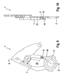
- the fine adjustment device shown has an unrest block 1 a protruding cylindrical projection forming a rear axle 2, on which a back 3 with its annular bearing part 4 is pivotally mounted.
- the retainer 3 protrudes radially from the annular bearing part 4 a pointer 5 with a pointer tip 6 at its free end.
- the pointer 5 projects into a chamber-like recess 7 of the balance cock 1.
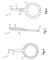
- a counter pressure spring 8 In the end region of the recess which is radially opposite the extension 2 7 is a counter pressure spring 8 by means of two screws 9 on it one end firmly connected to the balance cock 1. Of that at the balance cock 1 screwed end portion of the counter pressure spring 8 protrudes arm-like holding area 10 approximately in the rotational direction of the pointer 5 approximately in its swivel range radially outside the pointer tip 6th
- a spring arm 11 connects in one piece, which is approximately concave extends approximately in the plane of the rear pointer 5.
- the spring arm 11 has one for longitudinal extension of the pointer 5 approximately convexly curved application area 12, which is directed to the pointer 5 and on this under Bias of the counter-pressure spring 8 is applied in the pivoting direction 13. This causes the pointer 5 to abut the head end of a regulating screw 14 held that the direction of action of the counter pressure spring 8 is opposite.
- the regulating screw 14 is in a thread of a threaded bore 15 in a side wall 16 of the recess 7 of the balance cock 1 arranged rotatably, protrudes with its end region having the head end into the recess 7 and serves to position the rear pointer Third
- convex arched hold-down area 20 Over a part of the thickness of the spring arm 11 is stepwise opposite convexly curved application area 12 is also convex arched hold-down area 20 further protrudes and protrudes into a recess 21 on the hold-down area 20 of the spring arm 11 Side of the pointer 5. The pointer 5 is thus against one Lifted off the bottom 22 of the recess 7 secured.
Landscapes
- Physics & Mathematics (AREA)
- General Physics & Mathematics (AREA)
- Safety Valves (AREA)
- Electromechanical Clocks (AREA)
- Organic Low-Molecular-Weight Compounds And Preparation Thereof (AREA)
- Detergent Compositions (AREA)
- Details Of Measuring And Other Instruments (AREA)
- Measuring Fluid Pressure (AREA)
- Control Of Fluid Pressure (AREA)
- Brushes (AREA)
Abstract
Description
- Figur 1
- eine Ansicht einer Feinreguliervorrichtung
- Figur 2
- eine Draufsicht einer Gegendruckfeder der Feinregulier-vorrichtung nach Figur 1
- Figur 3
- eine Seitenansicht der Gegendruckfeder nach Figur 2
- Figur 4
- eine Rückansicht der Gegendruckfeder nach Figur 2
- Figur 5
- eine Schnittansicht der Gegendruckfeder nach Figur 2 entlang der Linie V - V in Figur 2
- Figur 6
- eine Ansicht eines Rückers der Feinreguliervorrichtung nach Figur 1
- Figur 7
- einen Querschnitt des Rückers nach Figur 6
- Figur 8
- eine Rückansicht des Rückers nach Figur 6
- Figur 9
- eine Ansicht eines Unruhklobens der Feinreguliervorrichtung nach Figur 1
- Figur 10
- eine Schnittansicht des Unruheklobens nach Figur 9 entlang der Linie X - X in Figur 9.
- 1
- Unruhkloben
- 2
- Ansatz
- 3
- Rücker
- 4
- Lagerteil
- 5
- Rückerzeiger
- 6
- Zeigerspitze
- 7
- Ausnehmung
- 8
- Gegendruckfeder
- 9
- Schrauben
- 10
- Haltebereich
- 11
- Federarm
- 12
- Beaufschlagungsbereich
- 13
- Schwenkrichtung
- 14
- Regulierschraube
- 15
- Gewindebohrung
- 16
- Seitenwand
- 17
- Gewindebohrung
- 18
- Feststellschraube
- 19
- Schraubenkopf
- 20
- Niederhaltebereich
- 21
- Vertiefung
- 22
- Boden
Claims (13)
- Feinreguliervorrichtung für den Rückerzeiger einer Uhr, mit einem Unruhkloben, auf dem ein Rücker um eine Rückerachse schwenkbar gelagert ist, mit einem in einem radialen Abstand zur Rückerachse an dem Rücker angeordneten Spiralschlüssel zur Veränderung der aktiven Länge einer Spirale des Schwingsystems der Uhr und mit einem radial gerichteten Rückerzeiger des Rückers, mit einer Gegendruckfeder, die als Federarm ausgebildet ist, der mit seinem einen Endbereich am Unruhkloben befestigt ist und mit seinem anderen freien Endbereich unter Vorspannung den Rückerzeiger in Schwenkrichtung beaufschlagt sowie in Anlage an einer Regulierschraube hält, die in einer Gewindebohrung des Unruhklobens oder eines mit dem Unruhkloben verbundenen Bauteils den Rückerzeiger in Gegenschwenkrichtung beaufschlagend verdrehbar angeordnet ist, dadurch gekennzeichnet, daß der Federarm (11) einen Niederhaltebereich (20) besitzt, der axial zur Rückerachse an der dem Unruhkloben (1) abgewandten und/oder zugewandten Seite des Rückerzeigers (5) anlegbar ist.
- Feinreguliervorrichtung nach Anspruch 1, dadurch gekennzeichn et, daß der Federarm (11) mit seinem Niederhaltebereich (21) mit geringer Vorspannkraft axial zur Rückerachse an dem Rückerzeiger (5) anlegbar ist.
- Feinreguliervorrichtung nach einem der vorhergehenden Ansprüche, dadurch gekennzeichnet, daß der freie Endbereich des Federarms (11) mit einem zur Längserstreckung des Rückerzeigers (5) etwa konvex gewölbten Beaufschlagungsbereich (12) am Rückerzeiger (5) in Anlage ist.
- Feinreguliervorrichtung nach einem der Ansprüche 1 bis 3, dadurch gekennzeichnet, daß der Niederhaltebereich (20) am freien Endbereich des Federarms (11), insbesondere im Bereich des Beaufschlagungsbereichs (12) angeordnet ist.
- Feinreguliervorrichtung nach einem der vorhergehenden Ansprüche, dadurch gekennzeichnet, daß Beaufschlagungsbereich (12) und Niederhaltebereich (20) etwa axial zur Rückerachse derart stufig nebeneinander angeordnet sind, daß der Niederhaltebereich (20) weiter in Richtung zum Rückerzeiger (5) ragt als der Beaufschlagungsbereich (12).
- Feinreguliervorrichtung nach einem der Ansprüche 1 bis 5, dadurch gekennzeichnet, daß der Rückerzeiger (5) auf seiner dem Niederhaltebereich (20) des Federarms (11) zugewandten Seite eine Vertiefung (21) besitzt, in die der Niederhaltebereich (20) hineinragt.
- Feinreguliervorrichtung nach einem der vorhergehenden Ansprüche, dadurch gekennzeichnet, daß Rückerzeiger (5) und Federarm (11) in etwa einer selben Ebene rechtwinklig zur Rückerzeigerachse angeordnet sind.
- Feinreguliervorrichtung nach einem der vorhergehenden Ansprüche, dadurch gekennzeichnet, daß der Federarm (11) der Gegendruckfeder (8) sich etwa konkav zur Längserstreckung des Rückerzeigers (5) erstreckt.
- Feinreguliervorrichtung nach Anspruch 8, dadurch gekennzeichnet, daß die Gegendruckfeder (8) einen Haltebereich (10) besitzt, der sich von dem an dem Unruhkloben (1) befestigten Ende der Gegendruckfeder (8) zu dem dem Niederhaltebereich (20) entgegengesetzten Ende des Federarms (11) erstreckt.
- Feinreguliervorrichtung nach Anspruch 9, dadurch gekennzeichnet, daß der Haltebereich (10) sich von dem an dem Unruhkloben (1) befestigten Ende etwa in Drehbewegungsrichtung (13) des Rückerzeigers (5) bis etwa in den Schwenkbereich der Zeigerspitze (6) des Rückerzeigers (5) erstreckt.
- Feinreguliervorrichtung nach einem der vorhergehenden Ansprüche, dadurch gekennzeichnet, daß der Unruhkloben (1) auf seiner dem Rückerzeiger (5) zugewandten Seite eine vertiefte Ausnehmung (7) besitzt, in der Rückerzeiger (5) und Gegendruckfeder (8) in ihrer Ebene rechtwinklig zur Rückerachse bewegbar angeordnet sind.
- Feinreguliervorrichtung nach Anspruch 11, dadurch gekennzeichnet, daß die Gewindebohrung (15) zur Aufnahme der Regulierschraube (14) in einer Seitenwand (16) der vertieften Ausnehmung (7) in dem Unruhkloben (1) ausgebildet ist.
- Feinreguliervorrichtung nach Anspruch 12, dadurch gekennzeichnet, daß axial zur Rückerachse unmittelbar neben der Gewindebohrung (15) zur Aufnahme der Regulierschraube (14) eine Gewindebohrung (17) zur Aufnahme einer Feststellschraube (18) ausgebildet ist, durch deren Schraubenkopf (19) die Regulierschraube (14) klemmend beaufschlagbar ist.
Applications Claiming Priority (2)
| Application Number | Priority Date | Filing Date | Title |
|---|---|---|---|
| DE10326198 | 2003-06-07 | ||
| DE10326198A DE10326198A1 (de) | 2003-06-07 | 2003-06-07 | Feinreguliervorrichtung |
Publications (3)
| Publication Number | Publication Date |
|---|---|
| EP1484653A2 true EP1484653A2 (de) | 2004-12-08 |
| EP1484653A3 EP1484653A3 (de) | 2007-10-03 |
| EP1484653B1 EP1484653B1 (de) | 2009-10-14 |
Family
ID=33154605
Family Applications (1)
| Application Number | Title | Priority Date | Filing Date |
|---|---|---|---|
| EP04012670A Expired - Lifetime EP1484653B1 (de) | 2003-06-07 | 2004-05-28 | Feinreguliervorrichtung |
Country Status (5)
| Country | Link |
|---|---|
| US (1) | US7036977B2 (de) |
| EP (1) | EP1484653B1 (de) |
| JP (1) | JP2004361389A (de) |
| AT (1) | ATE445866T1 (de) |
| DE (2) | DE10326198A1 (de) |
Families Citing this family (7)
| Publication number | Priority date | Publication date | Assignee | Title |
|---|---|---|---|---|
| US9282081B2 (en) | 2005-07-28 | 2016-03-08 | Vaporstream Incorporated | Reduced traceability electronic message system and method |
| CH699021B1 (fr) * | 2006-03-17 | 2010-01-15 | Bnb Concept Sa | Module de base pour pièce d'horlogerie, notamment montre-bracelet. |
| JP5729666B2 (ja) * | 2010-09-14 | 2015-06-03 | セイコーインスツル株式会社 | 時計用デテント脱進機、および機械式時計 |
| EP2980658B1 (de) * | 2014-08-01 | 2017-07-19 | Agenhor SA | Vorrichtung zum Zusammenbau und Regulieren einer Spirale |
| US10545650B2 (en) * | 2015-08-12 | 2020-01-28 | International Business Machines Corporation | Application for auto deletion of images |
| CH714480A2 (fr) * | 2017-12-20 | 2019-06-28 | Swatch Group Res & Dev Ltd | Dispositif de réglage autonome de la longueur active d'un spiral. |
| CN116819926B (zh) * | 2023-05-22 | 2025-12-23 | 广州一秒钟表有限公司 | 一种机械表走时调整装置 |
Family Cites Families (10)
| Publication number | Priority date | Publication date | Assignee | Title |
|---|---|---|---|---|
| CH351220A (fr) * | 1958-12-13 | 1960-12-31 | Surdez Fernand | Dispositif pour agir de l'extérieur sur la raquette d'un mouvement d'horlogerie |
| CH381160A (fr) * | 1962-03-31 | 1964-03-31 | Bueren Watch Company S A | Dispositif de raquetterie pour mouvement d'horlogerie |
| CH1201968A4 (de) * | 1968-08-09 | 1970-07-31 | ||
| JPS491012Y1 (de) * | 1969-05-24 | 1974-01-11 | ||
| DE2055063B2 (de) * | 1970-11-09 | 1975-05-15 | Gebrueder Junghans Gmbh, 7230 Schramberg | Vorrichtung zur Feinregulierung einer Unruh |
| US3638419A (en) * | 1971-03-22 | 1972-02-01 | Timex Corp | Horological hairspring regulator |
| US3745763A (en) * | 1972-07-07 | 1973-07-17 | Schild Sa A | Fine adjustment device for watch movement regulator assembly |
| CH577194B5 (de) * | 1973-06-08 | 1976-06-30 | Ebauches Bettlach Sa | |
| CH610468B5 (de) * | 1975-11-04 | 1979-04-30 | Ebauchesfabrik Eta Ag | |
| DE4435704C2 (de) * | 1994-10-06 | 1997-04-24 | Lange Uhren Gmbh | Schwingsystem |
-
2003
- 2003-06-07 DE DE10326198A patent/DE10326198A1/de not_active Ceased
-
2004
- 2004-03-26 JP JP2004091541A patent/JP2004361389A/ja active Pending
- 2004-05-28 DE DE502004010220T patent/DE502004010220D1/de not_active Expired - Lifetime
- 2004-05-28 AT AT04012670T patent/ATE445866T1/de not_active IP Right Cessation
- 2004-05-28 EP EP04012670A patent/EP1484653B1/de not_active Expired - Lifetime
- 2004-06-02 US US10/859,035 patent/US7036977B2/en not_active Expired - Lifetime
Also Published As
| Publication number | Publication date |
|---|---|
| US20050013201A1 (en) | 2005-01-20 |
| ATE445866T1 (de) | 2009-10-15 |
| DE502004010220D1 (de) | 2009-11-26 |
| EP1484653A3 (de) | 2007-10-03 |
| US7036977B2 (en) | 2006-05-02 |
| DE10326198A1 (de) | 2004-12-30 |
| EP1484653B1 (de) | 2009-10-14 |
| JP2004361389A (ja) | 2004-12-24 |
Similar Documents
| Publication | Publication Date | Title |
|---|---|---|
| EP0546376B1 (de) | Oberfräse | |
| WO2002024387A1 (de) | Zerspanungswerkzeug | |
| EP0676990B1 (de) | Klemmhalter für schneidplatten | |
| DE69812976T2 (de) | Schneidwerkzeug | |
| EP1484653A2 (de) | Feinreguliervorrichtung | |
| WO2000060199A1 (de) | Verstellvorrichtung für ausstellfenster | |
| EP0257014A2 (de) | Geräuscharmes Ventil | |
| EP1521140B1 (de) | Schwingsystem | |
| EP0702386A1 (de) | Schwenkbares Betätigungsglied für einen Sicherheitsschalter | |
| EP0215281A2 (de) | Flügellager für ein Fenster, eine Tür od. dgl. | |
| EP0552607B1 (de) | Scharniertopf | |
| EP0178599B1 (de) | Stellventil, insbesondere Drosselventil | |
| EP0011681A1 (de) | Barometer | |
| CH687493B5 (de) | Schwingsystem. | |
| DE102007015015B4 (de) | Absperrscheibenantrieb für absperrbare Armaturen | |
| WO2004037473A2 (de) | Maschinenwerkzeug mit verstellbarer schneide | |
| WO2020007565A1 (de) | Ventiloberteil | |
| DE102007033361B4 (de) | Vorrichtung und Verfahren zum Abdichten der Einstellkrone einer Uhr | |
| EP1887151A2 (de) | Gelenkhalterung | |
| DE9016756U1 (de) | Schraubenschlüssel für Wasserhähne | |
| DE9110737U1 (de) | Einrichtung zum Spannen einer Scheidplatte | |
| EP2562460B1 (de) | Einstellvorrichtung | |
| DE1281956B (de) | Unruhlagerung | |
| DE29809791U1 (de) | Stellwand | |
| DE3041755A1 (de) | Feste verschraubung zwischen einer schraube und einer mutter |
Legal Events
| Date | Code | Title | Description |
|---|---|---|---|
| PUAI | Public reference made under article 153(3) epc to a published international application that has entered the european phase |
Free format text: ORIGINAL CODE: 0009012 |
|
| AK | Designated contracting states |
Kind code of ref document: A2 Designated state(s): AT BE BG CH CY CZ DE DK EE ES FI FR GB GR HU IE IT LI LU MC NL PL PT RO SE SI SK TR |
|
| AX | Request for extension of the european patent |
Extension state: AL HR LT LV MK |
|
| PUAL | Search report despatched |
Free format text: ORIGINAL CODE: 0009013 |
|
| AK | Designated contracting states |
Kind code of ref document: A3 Designated state(s): AT BE BG CH CY CZ DE DK EE ES FI FR GB GR HU IE IT LI LU MC NL PL PT RO SE SI SK TR |
|
| AX | Request for extension of the european patent |
Extension state: AL HR LT LV MK |
|
| RIC1 | Information provided on ipc code assigned before grant |
Ipc: G04B 18/02 20060101AFI20070827BHEP |
|
| 17P | Request for examination filed |
Effective date: 20071005 |
|
| AKX | Designation fees paid |
Designated state(s): AT CH DE LI |
|
| GRAP | Despatch of communication of intention to grant a patent |
Free format text: ORIGINAL CODE: EPIDOSNIGR1 |
|
| GRAS | Grant fee paid |
Free format text: ORIGINAL CODE: EPIDOSNIGR3 |
|
| GRAA | (expected) grant |
Free format text: ORIGINAL CODE: 0009210 |
|
| AK | Designated contracting states |
Kind code of ref document: B1 Designated state(s): AT CH DE LI |
|
| REG | Reference to a national code |
Ref country code: CH Ref legal event code: EP |
|
| REF | Corresponds to: |
Ref document number: 502004010220 Country of ref document: DE Date of ref document: 20091126 Kind code of ref document: P |
|
| PLBE | No opposition filed within time limit |
Free format text: ORIGINAL CODE: 0009261 |
|
| STAA | Information on the status of an ep patent application or granted ep patent |
Free format text: STATUS: NO OPPOSITION FILED WITHIN TIME LIMIT |
|
| 26N | No opposition filed |
Effective date: 20100715 |
|
| PG25 | Lapsed in a contracting state [announced via postgrant information from national office to epo] |
Ref country code: AT Free format text: LAPSE BECAUSE OF NON-PAYMENT OF DUE FEES Effective date: 20100528 |
|
| PGFP | Annual fee paid to national office [announced via postgrant information from national office to epo] |
Ref country code: DE Payment date: 20231030 Year of fee payment: 20 Ref country code: CH Payment date: 20231108 Year of fee payment: 20 |
|
| REG | Reference to a national code |
Ref country code: DE Ref legal event code: R071 Ref document number: 502004010220 Country of ref document: DE |
|
| REG | Reference to a national code |
Ref country code: CH Ref legal event code: PL |