EP1484660A2 - Arrangement de pédales pour véhicule automobile - Google Patents
Arrangement de pédales pour véhicule automobile Download PDFInfo
- Publication number
- EP1484660A2 EP1484660A2 EP04102291A EP04102291A EP1484660A2 EP 1484660 A2 EP1484660 A2 EP 1484660A2 EP 04102291 A EP04102291 A EP 04102291A EP 04102291 A EP04102291 A EP 04102291A EP 1484660 A2 EP1484660 A2 EP 1484660A2
- Authority
- EP
- European Patent Office
- Prior art keywords
- pedal
- actuated
- actuating
- deflection
- traction means
- Prior art date
- Legal status (The legal status is an assumption and is not a legal conclusion. Google has not performed a legal analysis and makes no representation as to the accuracy of the status listed.)
- Granted
Links
Images

Classifications
-
- G—PHYSICS
- G05—CONTROLLING; REGULATING
- G05G—CONTROL DEVICES OR SYSTEMS INSOFAR AS CHARACTERISED BY MECHANICAL FEATURES ONLY
- G05G1/00—Controlling members, e.g. knobs or handles; Assemblies or arrangements thereof; Indicating position of controlling members
- G05G1/30—Controlling members actuated by foot
- G05G1/40—Controlling members actuated by foot adjustable
- G05G1/405—Controlling members actuated by foot adjustable infinitely adjustable
Definitions
- the invention relates to an arrangement of a pedal or one around Articulated actuator, especially for a Motor vehicle mechanically coupled to an element to be actuated and compared to this without actuating the pedal or actuator in a substantially perpendicular to the pivot axis of the pedal or Actuator extending direction is longitudinally displaceable, the Transmission behavior when the pedal or actuator is actuated essentially independent of a longitudinal displacement of the same is.
- DE 100 26 751 A1 directed.
- the braking system is actuated in motor vehicles, a possibly existing coupling, as well as the load requestor for the Vehicle drive unit using pedals. Not just an optimal sitting position for the driver of the motor vehicle, but also an optimal operating position To enable these pedals, these pedals can be relocatable independently of an operation, i.e. that a pedal or the pedals in the rest position different positions in the vehicle footwell can take. However, it is often not possible for that element to be operated by means of the pedal together with the pedal is shifted. For example. this applies to a brake booster with attached Tandem master cylinder combined with a relocatable one Brake pedal.
- a simple and compact pedal arrangement (or generally one corresponding arrangement for a pivotable about a joint Actuator) to show according to the preamble of claim 1 Object of the present invention.
- the solution to this problem is characterized in that one by one stationary pivot point pivotable intermediate lever is provided, the one side of this pivot point with the one to be operated Element is connected and on the other side of a flexible traction is connected in the form of a simple pulley system via a first one with the pedal or actuator when operated shifted redirection as well as a second redirection that together with a longitudinal displacement of the pedal or actuator without Operation of the same is shifted to a fixed connection point is led.
- Advantageous training and further education are the content of the subclaims, in most cases only one pedal is spoken of, although a corresponding transfer to any actuator, For example, a hand lever or the like. is easily possible.
- a proposed cable or generally a traction device which is similar a simple pulley over suitably arranged (as indicated)
- Deflection pulleys or generally deflections is characterized by simple construction and provides a desired so-called length compensation, which with regard to an essentially constant and in particular of a pedal shift independent so-called transmission behavior Pedal actuation is needed safely.
- This so-called pulley or the multiple deflected traction means runs essentially in the same direction in which the pedal (or generally actuator) to Setting different rest positions can be shifted.
- the said simple construction results from the fact that none elaborate joints in this by the traction means or the cable formed transmission mechanism between the pedal and the actuating element are present.
- a relatively simple structure is also retained when off Security reasons in terms of redundancy next to each other two (or several) traction means via corresponding deflections, in particular Deflection rollers are guided. From a security point of view, too Monitoring of the integrity of the traction device is provided be, because a failure of the same would have in particular in connection with a Vehicle braking system, i.e. if the brake pedal over this traction device acts on the braking device or the brake booster, serious Consequences. In this sense, when using an electrically conductive Material for the traction device an electrical circuit arrangement be provided, with the help of which the integrity of the traction means successful power line between the two ends of the traction device can be monitored.
- This module carrier can, for example, by means of a linear drive two on the side in the footwell of the motor vehicle (for example a passenger car) attached longitudinal rails to be displaceably guided.
- a ball-guided or slide-guided longitudinal guide can come with Spindle drive, for example analogous to the known electromechanical longitudinal seat adjustment in passenger cars, with a central arrangement Electric motor and transmission through flexible shafts.
- the module carrier in question can also have rigidity in addition to the vehicle front wall towards a non-critical one with regard to intrusion (in the event of a vehicle crash) Area is supported by a passive longitudinal guide, where it is possible, the module carrier with a view to a targeted deformation behavior to be interpreted in the event of a crash.
- Column between the module carrier and the Vehicle floor can be covered by means of a brush strip or by means of a bellows sealed.
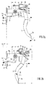
- FIG. 1 a shows a pedal that is not actuated and is therefore in the rest position in a first position
- FIG. 2 a shows this pedal, which is displaced relative to the first position, in the rest position in a second position.
- the pedal is actuated starting from its first position according to FIG. 1a, specifically by an actuation path z.
- the pedal in the illustration according to FIG. 2b is actuated by the same actuation path z measured on the step plate.
- Reference numeral 1 denotes a pedal for a motor vehicle, at which can in particular be the brake pedal.
- the so-called. push rod 2 is not shown in a figure Brake booster actuated, in an alternative embodiment between the push rod 2 and the pedal arrangement described below a suitable intermediate element, for example in the form of a so-called. Actuating rod can be provided.
- the push rod 2 or one just mentioned actuating rod or the like can thus be actuated Element referred to in the sense of the claim.
- the push rod 2 penetrates the footwell end wall 3 of the motor vehicle, especially passenger car, in a breakthrough 4.
- this Breakthrough 4 used and suitably attached to the end wall 3 is a Support structure 5 for the pedal arrangement described below, wherein this support structure 5 of course also a necessary passage for the push rod 2 to the left of the end wall 3 in the figures arranged and preferably attached to this brake booster having.
- the pedestal 6 supports the pedal 1, specifically via its swivel joint or swivel joints 1a, which is only visible in FIGS. 2a, 2b , but is covered by the support arm 5a in the other two figures or will.
- a joint 1a arranged on the bearing block 6 is provided, in the present sectional view only one of these two joints 1a is of course visible.
- pivot joints 1a To this suitably arranged on the bearing block 6 pivot joints 1a is therefore the pedal 1, which is provided, as usual, b at its free lower end with a step plate 1, starting from its rest position shown in Figures 1a, 2a as shown by arrow 8 pivotable, namely about a swivel axis 15, which runs through the center of the swivel joint (s) 1a in the figure representations perpendicular to the plane of the drawing.
- this pivot axis 15 runs perpendicular to the possible direction of displacement of the pedal 1 or here of the pedestal 6, which is described here by the direction of the arrow 7, ie the pedal 1, which is pivoted about the pivot axis 15 when it is actuated, can be displaced in its rest position in a direction perpendicular to the pivot axis 15, namely in or against the direction of the arrow 7, namely by displacing the bearing block 6.
- the traction device 12 Starting from the attachment point on the intermediate lever 10 is the traction device 12 first according to arrow direction 7 to a first deflection 13 or Deflection roller 13 is guided and is then over this over substantially 180 ° while reversing the direction essentially opposite arrow direction 7 to one second deflection 14 or pulley 14 guided.
- This second too Deflection roller 14 wraps around the traction means 12 or rope 12 over approximately 180 ° and is thus redirected again in the direction of arrow 7 to finally with his attached to the other end on the support arm 5a in the region of its free end be a so-called fixed, since not relocatable connection point 16.
- the rope 12 is thus in the form of a simple pulley performed, which is essentially in the direction of the possible pedal displacement runs.
- the first deflection 13 is in the form of a first deflection roller 13 on the pedal 1 attached, namely on the tread plate 1b of the pedal 1 with respect to it Swivel joint (s) 1a opposite end of the pedal 1 or Pedal lever, so that this first deflection 13 when the Pedals 1 is shifted.
- the second deflection 14 is in the form of a second Deflection roller 14 attached to the bearing block 6, so that this at one Relocation of the bearing block 6 together with this is not however in connection with an actuation of the pedal 1.
- FIGS. 1a , 1b it can be seen that, starting from the (first) rest position according to FIG. 1a, when the pedal 1 is actuated and thus when it is pivoted according to the direction of the arrow 8 due to the resulting displacement of the first deflection roller 14 Intermediate lever 10 is also pivoted about its pivot point 11 according to arrow direction 8, so that when the state according to FIG. 1b is reached, the push rod 2 has been displaced by a certain distance y according to arrow direction 9.
- the pedal tread plate 1 b was displaced by a distance z by pivoting in the direction of the arrow 8, which is likewise measured essentially in the direction of the arrow 9.
- the state according to FIG. 2a can also be established, specifically by moving the pedal 1 according to the direction of the arrow 7 without actuating the same.
- This shifting of the pedal 1 takes place via a shifting of the bearing block 6 in order to obtain a different pedal position (particularly in the rest position of the latter) which is more comfortable for the respective driver.
- the two deflections 13 and 14 are displaced by the same distance x in the same direction in this displacement of the bearing block 6 according to the direction of the arrow 7, for example by a distance x, this causes this Displacement no pivoting of the intermediate lever 10 and thus also no displacement of the push rod 2. (However, with such a displacement of the pedal 1 or bearing block 6, the two deflections 13, 14 are rotated about their axis of rotation).
- the intermediate lever 10 is also pivoted about its pivot point 11 in the direction of the arrow 8 due to the resulting displacement of the first deflection roller 14, to the extent that when the state according to FIG. 2b is reached, the push rod 2 is displaced by a certain distance y in the direction of the arrow 9 if the footplate 1b of the pedal 1 is displaced by a distance z (measured essentially in the direction of the arrow 9).
- the distances z and y mentioned in FIGS. 2b and 1b are of equal size, ie regardless of whether the pedal is in its first rest position according to FIG.
- a traction means 12 in Form of a (steel) rope 12 but it is recommended Security reasons in the sense of redundancy almost side by side or in the figures "one behind the other" at least two such traction means 12 or To provide ropes 12, the deflection rollers 13, 14 also being double or are or may be present more than once.
- the traction means 12 or the rope (s) 12 can also be made from others metallic or non-metallic materials, e.g. Kevlar fibers, consist. Instead of a rope, a chain or a flat belt or a toothed belt or a flat belt is used become.
- Rope compensation or compensation via a suitably deflected guided flexible Traction means advantageously requires no synchronization and none own drive and at the same time offers an almost constant gear ratio over the possible pedal displacement area and is also characterized by a relatively simple structure and in particular due to a small space requirement for the vehicle bulkhead or Footwell end wall.
- Pedal module for an adjustable pedal set forms to arrange.
- the one in Exemplary embodiment with the reference numeral 6 bearing bracket can then be attached to this module carrier or form it.
- an ergonomically correct, simple joint adjustment of Footrest, if necessary clutch pedal, brake pedal and accelerator pedal ( load request transmitter for the vehicle drive unit) possible.
- the Pedal module or, in the case of an adjustable pedal module, its longitudinal adjustment mechanism can simply on the boundary walls of the vehicle footwell are supported, for example on the A-pillar and on the transmission tunnel.
Landscapes
- Physics & Mathematics (AREA)
- General Physics & Mathematics (AREA)
- Engineering & Computer Science (AREA)
- Automation & Control Theory (AREA)
- Mechanical Control Devices (AREA)
- Braking Elements And Transmission Devices (AREA)
- Auxiliary Drives, Propulsion Controls, And Safety Devices (AREA)
Applications Claiming Priority (2)
| Application Number | Priority Date | Filing Date | Title |
|---|---|---|---|
| DE10324992 | 2003-06-03 | ||
| DE2003124992 DE10324992A1 (de) | 2003-06-03 | 2003-06-03 | Pedal-Anordnung für ein Kraffahrzeug |
Publications (3)
| Publication Number | Publication Date |
|---|---|
| EP1484660A2 true EP1484660A2 (fr) | 2004-12-08 |
| EP1484660A3 EP1484660A3 (fr) | 2006-04-05 |
| EP1484660B1 EP1484660B1 (fr) | 2007-01-24 |
Family
ID=33154523
Family Applications (1)
| Application Number | Title | Priority Date | Filing Date |
|---|---|---|---|
| EP20040102291 Expired - Lifetime EP1484660B1 (fr) | 2003-06-03 | 2004-05-25 | Arrangement de pédales pour véhicule automobile |
Country Status (2)
| Country | Link |
|---|---|
| EP (1) | EP1484660B1 (fr) |
| DE (2) | DE10324992A1 (fr) |
Cited By (2)
| Publication number | Priority date | Publication date | Assignee | Title |
|---|---|---|---|---|
| CN112046280A (zh) * | 2020-09-27 | 2020-12-08 | 奇瑞万达贵州客车股份有限公司 | 一种全承载式公路车的离合器操作机构 |
| DE102022116257A1 (de) | 2022-06-29 | 2024-01-04 | Bayerische Motoren Werke Aktiengesellschaft | Anordnung eines Pedallagerbocks an einer Stirnwand eines Kraftwagens sowie Kraftwagen |
Families Citing this family (2)
| Publication number | Priority date | Publication date | Assignee | Title |
|---|---|---|---|---|
| CN108099882B (zh) * | 2018-01-02 | 2020-06-26 | 北京汽车股份有限公司 | 机械助力式制动系统及具有其的车辆 |
| DE102018004362B4 (de) | 2018-06-01 | 2019-12-12 | Psa Automobiles Sa | Pedalanordnung für ein Kraftfahrzeug |
Family Cites Families (5)
| Publication number | Priority date | Publication date | Assignee | Title |
|---|---|---|---|---|
| US3691868A (en) * | 1971-07-06 | 1972-09-19 | Raymond P Smith | Adjustable pedal |
| US3754480A (en) * | 1972-05-08 | 1973-08-28 | Gen Motors Corp | Vehicle control apparatus |
| EP0363546A1 (fr) * | 1987-05-22 | 1990-04-18 | Wickes Manufacturing Company | Ensemble réglable de pédales d'accélérateur et de frein |
| US6293584B1 (en) * | 1998-09-23 | 2001-09-25 | Vehicle Safety Systems, Inc. | Vehicle air bag minimum distance enforcement apparatus, method and system |
| DE10026751A1 (de) * | 2000-05-30 | 2001-12-06 | Wolf Woco & Co Franz J | Pedalerie und Pedalsystem mit einer Vielzahl von solchen Pedalerien |
-
2003
- 2003-06-03 DE DE2003124992 patent/DE10324992A1/de not_active Withdrawn
-
2004
- 2004-05-25 EP EP20040102291 patent/EP1484660B1/fr not_active Expired - Lifetime
- 2004-05-25 DE DE200450002734 patent/DE502004002734D1/de not_active Expired - Lifetime
Cited By (2)
| Publication number | Priority date | Publication date | Assignee | Title |
|---|---|---|---|---|
| CN112046280A (zh) * | 2020-09-27 | 2020-12-08 | 奇瑞万达贵州客车股份有限公司 | 一种全承载式公路车的离合器操作机构 |
| DE102022116257A1 (de) | 2022-06-29 | 2024-01-04 | Bayerische Motoren Werke Aktiengesellschaft | Anordnung eines Pedallagerbocks an einer Stirnwand eines Kraftwagens sowie Kraftwagen |
Also Published As
| Publication number | Publication date |
|---|---|
| DE502004002734D1 (de) | 2007-03-15 |
| EP1484660B1 (fr) | 2007-01-24 |
| EP1484660A3 (fr) | 2006-04-05 |
| DE10324992A1 (de) | 2004-12-23 |
Similar Documents
| Publication | Publication Date | Title |
|---|---|---|
| DE19602620B4 (de) | Bremsenbetätigungsvorrichtung | |
| EP2744692B1 (fr) | Mechanisme de freinage electromechanique | |
| EP2313296B1 (fr) | Dispositif d'actionnement du frein d'un véhicule | |
| DE19921552C2 (de) | Betätigungspedal für die Bremsanlage eines Straßenfahrzeuges | |
| EP0897442B1 (fr) | Installation pour la distribution de beton | |
| DE60219764T2 (de) | Kupplungspedal fur ein kraftfahrzeug | |
| DE2730959C3 (de) | Zuspannvorrichtung für Reibungsbremsen, insbesondere von Schienenfahrzeugen | |
| EP1484660B1 (fr) | Arrangement de pédales pour véhicule automobile | |
| EP1593571B1 (fr) | Installation de frein à sabot pour un bogie d'un véhicule ferroviaire avec bielles de support à logement sphérique | |
| EP0816156B1 (fr) | Dispositif permettant l'actionnement manuel d'un organe de commande moteur d'un véhicule | |
| EP0562598A1 (fr) | Assemblage à rotule entre deux véhicules articulés | |
| WO2019201797A1 (fr) | Installation de convoyage avec un chariot de convoyage | |
| DE2922109C2 (de) | Bremsbetätigungseinrichtung für Parkbremsen | |
| WO2004108492A1 (fr) | Ensemble pedale | |
| DE19938271A1 (de) | Pedal für ein Kraftfahrzeug, insbesondere Brems- oder Kupplungspedal | |
| EP4069619A1 (fr) | Appareil de guidage et de freinage d'un corps mobile d'un système de levage, ledit corps devant être déplacé le long d'une voie de guidage | |
| DE60201307T2 (de) | Einstellvorrichtung zum Verstellen der Lage eines Pedals | |
| DE10354377A1 (de) | Verstellbares Fußhebelwerk | |
| DE102010031371B4 (de) | Fußhebelwerk mit Hebelkinematik | |
| DE10336344A1 (de) | Bedienpedaleinrichtung für Kraftfahrzeuge | |
| EP3972880B1 (fr) | Dispositif de déserrage d'urgence pour frein de véhicule | |
| DE10328108B4 (de) | Verstellbares Fußhebelwerk | |
| DE202022107196U1 (de) | Kraftfahrzeug mit Ladeplattform | |
| DE29909613U1 (de) | Feststellbremse für Kraftfahrzeuge | |
| EP4389518A1 (fr) | Véhicule automobile avec plate-forme de chargement |
Legal Events
| Date | Code | Title | Description |
|---|---|---|---|
| PUAI | Public reference made under article 153(3) epc to a published international application that has entered the european phase |
Free format text: ORIGINAL CODE: 0009012 |
|
| AK | Designated contracting states |
Kind code of ref document: A2 Designated state(s): AT BE BG CH CY CZ DE DK EE ES FI FR GB GR HU IE IT LI LU MC NL PL PT RO SE SI SK TR |
|
| AX | Request for extension of the european patent |
Extension state: AL HR LT LV MK |
|
| PUAL | Search report despatched |
Free format text: ORIGINAL CODE: 0009013 |
|
| AK | Designated contracting states |
Kind code of ref document: A3 Designated state(s): AT BE BG CH CY CZ DE DK EE ES FI FR GB GR HU IE IT LI LU MC NL PL PT RO SE SI SK TR |
|
| AX | Request for extension of the european patent |
Extension state: AL HR LT LV MK |
|
| 17P | Request for examination filed |
Effective date: 20060516 |
|
| GRAP | Despatch of communication of intention to grant a patent |
Free format text: ORIGINAL CODE: EPIDOSNIGR1 |
|
| GRAS | Grant fee paid |
Free format text: ORIGINAL CODE: EPIDOSNIGR3 |
|
| AKX | Designation fees paid |
Designated state(s): DE FR GB IT |
|
| GRAA | (expected) grant |
Free format text: ORIGINAL CODE: 0009210 |
|
| AK | Designated contracting states |
Kind code of ref document: B1 Designated state(s): DE FR GB IT |
|
| REG | Reference to a national code |
Ref country code: GB Ref legal event code: FG4D Free format text: NOT ENGLISH |
|
| GBT | Gb: translation of ep patent filed (gb section 77(6)(a)/1977) |
Effective date: 20070207 |
|
| REF | Corresponds to: |
Ref document number: 502004002734 Country of ref document: DE Date of ref document: 20070315 Kind code of ref document: P |
|
| ET | Fr: translation filed | ||
| PLBE | No opposition filed within time limit |
Free format text: ORIGINAL CODE: 0009261 |
|
| STAA | Information on the status of an ep patent application or granted ep patent |
Free format text: STATUS: NO OPPOSITION FILED WITHIN TIME LIMIT |
|
| 26N | No opposition filed |
Effective date: 20071025 |
|
| PGFP | Annual fee paid to national office [announced via postgrant information from national office to epo] |
Ref country code: FR Payment date: 20100610 Year of fee payment: 7 |
|
| PGFP | Annual fee paid to national office [announced via postgrant information from national office to epo] |
Ref country code: IT Payment date: 20100528 Year of fee payment: 7 |
|
| PGFP | Annual fee paid to national office [announced via postgrant information from national office to epo] |
Ref country code: GB Payment date: 20100527 Year of fee payment: 7 |
|
| GBPC | Gb: european patent ceased through non-payment of renewal fee |
Effective date: 20110525 |
|
| REG | Reference to a national code |
Ref country code: FR Ref legal event code: ST Effective date: 20120131 |
|
| PG25 | Lapsed in a contracting state [announced via postgrant information from national office to epo] |
Ref country code: IT Free format text: LAPSE BECAUSE OF NON-PAYMENT OF DUE FEES Effective date: 20110525 |
|
| PG25 | Lapsed in a contracting state [announced via postgrant information from national office to epo] |
Ref country code: FR Free format text: LAPSE BECAUSE OF NON-PAYMENT OF DUE FEES Effective date: 20110531 |
|
| PG25 | Lapsed in a contracting state [announced via postgrant information from national office to epo] |
Ref country code: GB Free format text: LAPSE BECAUSE OF NON-PAYMENT OF DUE FEES Effective date: 20110525 |
|
| PGFP | Annual fee paid to national office [announced via postgrant information from national office to epo] |
Ref country code: DE Payment date: 20160521 Year of fee payment: 13 |
|
| REG | Reference to a national code |
Ref country code: DE Ref legal event code: R119 Ref document number: 502004002734 Country of ref document: DE |
|
| PG25 | Lapsed in a contracting state [announced via postgrant information from national office to epo] |
Ref country code: DE Free format text: LAPSE BECAUSE OF NON-PAYMENT OF DUE FEES Effective date: 20171201 |