EP1485134B1 - Verfahren und vorrichtung zur messung und kontrolle des kreislaufs von flüssigkeiten in endoskopkanälen - Google Patents
Verfahren und vorrichtung zur messung und kontrolle des kreislaufs von flüssigkeiten in endoskopkanälen Download PDFInfo
- Publication number
- EP1485134B1 EP1485134B1 EP20030718874 EP03718874A EP1485134B1 EP 1485134 B1 EP1485134 B1 EP 1485134B1 EP 20030718874 EP20030718874 EP 20030718874 EP 03718874 A EP03718874 A EP 03718874A EP 1485134 B1 EP1485134 B1 EP 1485134B1
- Authority
- EP
- European Patent Office
- Prior art keywords
- endoscope
- channels
- vessel
- channel
- chamber
- Prior art date
- Legal status (The legal status is an assumption and is not a legal conclusion. Google has not performed a legal analysis and makes no representation as to the accuracy of the status listed.)
- Expired - Lifetime
Links
Images
Classifications
-
- A—HUMAN NECESSITIES
- A61—MEDICAL OR VETERINARY SCIENCE; HYGIENE
- A61B—DIAGNOSIS; SURGERY; IDENTIFICATION
- A61B1/00—Instruments for performing medical examinations of the interior of cavities or tubes of the body by visual or photographical inspection, e.g. endoscopes; Illuminating arrangements therefor
- A61B1/12—Instruments for performing medical examinations of the interior of cavities or tubes of the body by visual or photographical inspection, e.g. endoscopes; Illuminating arrangements therefor with cooling or rinsing arrangements
- A61B1/121—Instruments for performing medical examinations of the interior of cavities or tubes of the body by visual or photographical inspection, e.g. endoscopes; Illuminating arrangements therefor with cooling or rinsing arrangements provided with means for cleaning post-use
- A61B1/123—Instruments for performing medical examinations of the interior of cavities or tubes of the body by visual or photographical inspection, e.g. endoscopes; Illuminating arrangements therefor with cooling or rinsing arrangements provided with means for cleaning post-use using washing machines
-
- A—HUMAN NECESSITIES
- A61—MEDICAL OR VETERINARY SCIENCE; HYGIENE
- A61B—DIAGNOSIS; SURGERY; IDENTIFICATION
- A61B1/00—Instruments for performing medical examinations of the interior of cavities or tubes of the body by visual or photographical inspection, e.g. endoscopes; Illuminating arrangements therefor
- A61B1/12—Instruments for performing medical examinations of the interior of cavities or tubes of the body by visual or photographical inspection, e.g. endoscopes; Illuminating arrangements therefor with cooling or rinsing arrangements
- A61B1/121—Instruments for performing medical examinations of the interior of cavities or tubes of the body by visual or photographical inspection, e.g. endoscopes; Illuminating arrangements therefor with cooling or rinsing arrangements provided with means for cleaning post-use
- A61B1/125—Instruments for performing medical examinations of the interior of cavities or tubes of the body by visual or photographical inspection, e.g. endoscopes; Illuminating arrangements therefor with cooling or rinsing arrangements provided with means for cleaning post-use using fluid circuits
-
- A—HUMAN NECESSITIES
- A61—MEDICAL OR VETERINARY SCIENCE; HYGIENE
- A61L—METHODS OR APPARATUS FOR STERILISING MATERIALS OR OBJECTS IN GENERAL; DISINFECTION, STERILISATION OR DEODORISATION OF AIR; CHEMICAL ASPECTS OF BANDAGES, DRESSINGS, ABSORBENT PADS OR SURGICAL ARTICLES; MATERIALS FOR BANDAGES, DRESSINGS, ABSORBENT PADS OR SURGICAL ARTICLES
- A61L2/00—Disinfection or sterilisation of materials or objects, in general; Accessories therefor
- A61L2/16—Disinfection or sterilisation of materials or objects, in general; Accessories therefor using chemical substances
- A61L2/18—Liquid substances
-
- A—HUMAN NECESSITIES
- A61—MEDICAL OR VETERINARY SCIENCE; HYGIENE
- A61L—METHODS OR APPARATUS FOR STERILISING MATERIALS OR OBJECTS IN GENERAL; DISINFECTION, STERILISATION OR DEODORISATION OF AIR; CHEMICAL ASPECTS OF BANDAGES, DRESSINGS, ABSORBENT PADS OR SURGICAL ARTICLES; MATERIALS FOR BANDAGES, DRESSINGS, ABSORBENT PADS OR SURGICAL ARTICLES
- A61L2/00—Disinfection or sterilisation of materials or objects, in general; Accessories therefor
- A61L2/24—Apparatus using programmed or automatic operation
-
- A—HUMAN NECESSITIES
- A61—MEDICAL OR VETERINARY SCIENCE; HYGIENE
- A61L—METHODS OR APPARATUS FOR STERILISING MATERIALS OR OBJECTS IN GENERAL; DISINFECTION, STERILISATION OR DEODORISATION OF AIR; CHEMICAL ASPECTS OF BANDAGES, DRESSINGS, ABSORBENT PADS OR SURGICAL ARTICLES; MATERIALS FOR BANDAGES, DRESSINGS, ABSORBENT PADS OR SURGICAL ARTICLES
- A61L2/00—Disinfection or sterilisation of materials or objects, in general; Accessories therefor
- A61L2/26—Accessories
- A61L2/28—Devices for testing the effectiveness or completeness of sterilisation or disinfection, e.g. indicators which change colour
-
- A—HUMAN NECESSITIES
- A61—MEDICAL OR VETERINARY SCIENCE; HYGIENE
- A61B—DIAGNOSIS; SURGERY; IDENTIFICATION
- A61B90/00—Instruments, implements or accessories specially adapted for surgery or diagnosis and not covered by any of the groups A61B1/00 - A61B50/00, e.g. for luxation treatment or for protecting wound edges
- A61B90/70—Cleaning devices specially adapted for surgical instruments
- A61B2090/701—Cleaning devices specially adapted for surgical instruments for flexible tubular instruments, e.g. endoscopes
-
- A—HUMAN NECESSITIES
- A61—MEDICAL OR VETERINARY SCIENCE; HYGIENE
- A61B—DIAGNOSIS; SURGERY; IDENTIFICATION
- A61B90/00—Instruments, implements or accessories specially adapted for surgery or diagnosis and not covered by any of the groups A61B1/00 - A61B50/00, e.g. for luxation treatment or for protecting wound edges
- A61B90/70—Cleaning devices specially adapted for surgical instruments
-
- A—HUMAN NECESSITIES
- A61—MEDICAL OR VETERINARY SCIENCE; HYGIENE
- A61L—METHODS OR APPARATUS FOR STERILISING MATERIALS OR OBJECTS IN GENERAL; DISINFECTION, STERILISATION OR DEODORISATION OF AIR; CHEMICAL ASPECTS OF BANDAGES, DRESSINGS, ABSORBENT PADS OR SURGICAL ARTICLES; MATERIALS FOR BANDAGES, DRESSINGS, ABSORBENT PADS OR SURGICAL ARTICLES
- A61L2103/00—Materials or objects being the target of disinfection or sterilisation
- A61L2103/15—Laboratory, medical or dentistry appliances, e.g. catheters or sharps
Definitions
- the present invention relates to a method and a device for measuring and controlling the circulation of fluids in the channels of endoscopes for verifying and recording the flow rate of cleaning, disinfecting, rinsing and drying solutions passing through the through each of the endoscopes' channels during operations to ensure their cleaning and disinfection.
- Endoscopes 1 are equipment used in the hospital environment. They comprise an operating unit 2 mounted at one end of an exploration tube 3 intended to be introduced by a natural conduit into an internal cavity of the body of a patient to perform the diagnosis of lesions or certain treatments such as for example, the extraction of foreign bodies, the destruction of tumors by coagulation or resection, the introduction of drugs or substances opaque to X-rays.
- the exploration head is connected by a second tube 4 to a proximal portion 5 having a series of injection connections 6.
- optical fibers guiding the light coming from a generator, image-carrying optical fibers or a video sensor (CCD) as well as various channels such as channel operators, channel aspiration, air supply channel, water supply channel, erector channel, washing channel.
- CCD video sensor
- various channels such as channel operators, channel aspiration, air supply channel, water supply channel, erector channel, washing channel.
- some of them can join in their downstream part to form only one channel. This may for example be the case of the air and water channels which form a common channel on the last centimeters of the insertion tube of the endoscope and the operating channels which join the suction channel.
- Flows circulating in the endoscope can also mix in a chamber (piston cage) having the same number of inputs as outputs.
- This manipulation is restrictive because it requires to irrigate each of the inputs of the different channels of the endoscope one after the other with all possible risks of contamination related to handling. It also requires rinsing and disinfecting the endoscope again.
- controllers have however been equipped with flow meters or pressure sensors to control the flow or pressure in each channel. These methods all try to determine the volume flowing in the channels in a unit of time. The volume is deduced from the interpretation of a measurement sensor (pressure drop, number of impulses of a wheel).
- the device forming the subject of the present invention makes it possible to ascertain with the aid of a limited number of devices not relying on the interpretation of sensors, that the fluids circulate in each of the internal channels of the endoscope with a well characterized and recorded flow during each phase of cleaning, disinfection, rinsing and drying of the endoscope.
- the invention ensures that each of them has been cleaned, disinfected, rinsed and dried by the guarantee of the presence of a sufficient volume of the solution concerned to saturate the channel during a definite time. It also makes it possible to use for each of the channels the optimum pressure and flow rate so as to ensure the optimal mechanical effect in the shortest possible time. Finally, it aims to provide the user with a fast and reliable way to collect at the end of the cycle all the portions of the internal channels of the endoscope in order to be able to analyze its possible state of contamination.
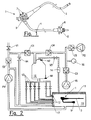
- the device consists of a hermetic chamber of a known volume provided with low and high level sensor to control its filling and emptying and whose upper part is connected to a filtered air compressor regulated by a pressure sensor , to a connecting solenoid valve allowing the air to be evacuated during filling of said chamber, to an injection pump for injecting a product promoting drying and to a cycling pump circulating the cleaning and disinfecting solutions.
- a vessel that can receive at least one endoscope, this vessel comprising injectors to which the channels of the endoscope can all be individually connected, said injectors being each connected to the lower part of the hermetic chamber via a tubing , an injection solenoid valve being disposed between the hermetic chamber and the injector on each of these pipes.
- control device object of the present application consists of a tank 10 and having a cover 11 equipped with an inflatable seal connected to a source of compressed air to ensure sealing all once the hood closed.
- a cycling pump P1 which mixes the solutions in the tank 10 in which the endoscope 1 is positioned.
- This pump feeds through a two non-return valve C1, C2 a hermetic chamber 12 of a known volume. preferably at least equal to one time the maximum volume of the largest of the channels of an endoscope.
- the tank 10 is filled by means of solenoid valves V1 and V4 connected to a network of rinsing water. This water is filtered at 0.2 microns.
- the solenoid valves are connected to the hydraulic circuit from the cycling pump between the valves C1 and C2.
- a heating body makes it possible to heat the outlets before re-injecting them into the tank by means of two types of injectors 13, 17 allowing, for some, to circulate the solutions around the external part of the endoscope 1 , for others to irrigate individually the internal channels of the device.
- the bottom of the tank is connected to a drain pump to reject the solutions in the wastewater network.
- Unused injectors will be connected to tubes of internal section less than 5 mm with a free end.
- the top of the hermetic chamber 12 is connected to a connecting solenoid valve V2 whose downstream is connected to the tank 10 or the cover 11 thereof via a quick connector 14 easily accessible from outside the the machine by the user and allowing quickly and easily to inject into the chamber by means of a syringe or pump a solution, for example a sample, which can be collected after opening one or more solenoid valves, at the end of one or more channels of the endoscope 1.
- the bottom of the chamber is connected to the injection solenoid valves V3 which each are connected to a specific injector connector 13 in the tank which connector is itself connected to one of the channel inputs of the endoscope 1.
- An injection pump P2 of drying liquid is connected through a non-return valve C5 at the line coming from the air compressor between the valves C3 and C4.
- the connecting solenoid valve (V2) is connected to the tank (10) or the cover (11) of the tank so that the air and the filling solutions of the hermetic chamber (12) can return to the chamber. tank either above or below the level of the liquid contained in said tank.
- the sealed chamber 12 is also equipped with a low level sensor N1 and a high level sensor N2.
- the system is equipped with a filtered air compressor which feeds the sealed chamber 12 through a line comprising a valve calibrated at a given pressure or two nonreturn valves C3, C4 between which is inserted bypass a sensor pressure 16 which regulates the pressure delivered in the chamber to different setpoints.
- All the electromechanical components are controlled by a microprocessor controller which, depending on the sensor status (level, pressure, temperature), manages the cycle as well as a set of interrupt alarms.
- a microprocessor controller which, depending on the sensor status (level, pressure, temperature), manages the cycle as well as a set of interrupt alarms.
- this tank can be treated one or more endoscopes.
- the endoscopes 1 which are treated in this device comprise a label or a chip that allows, by means of a reader, to inform the automaton of the mark of the endoscope, its serial number and its type.
- the automaton was previously programmed with the data of the endoscope manufacturers concerning the length and the diameter of the channels which constitute it.
- separators are previously placed in the piston cage 7 ( Figure 1) common to the air and water channels so as to separate the flows. These separator are machined so as to maintain a tiny communication between the two circuits allowing the disinfectant to act and not to create a non-disinfectable dead zone. The communication must not allow a leak greater than 30% of the flow of each of them.
- the endoscope connection fitting will be equipped with a shutter that will only allow circulation if the fitting is properly connected to the endoscope. the entrance to the canal.
- Each of the inputs of the endoscope is connected to a separate injector 13 located in the tank 10 and can be identified for the connection of at least one of the following channels: biopsy channel, suction channel, auxiliary biopsy channel or the water-jet channel, air channel, water channel, erector channel and auxiliary water channel.
- all the solenoid valves V3 channels are open so that the flow from the filling solenoid valve V1 (filtered water irrigation) or the cycling pump P1 (irrigation cleaning solution or disinfectant) passes freely in the tank 10 to irrigate all the channels.
- the device also makes it possible to control a volume of drying liquid (alcohol for example) injected into the channels. For this, the connecting solenoid valve V2 and the pump P2 of drying liquid are activated until the high level (sensor N2) of the chamber 12 is reached.
- a volume of drying liquid alcohol for example
- the cover 11 is open and without the need to disconnect the endoscope 1, samples can be taken.
- the quick connector 14 will be disconnected and the part coming from the hermetic chamber 12 is connected to the downstream of the body of a peristaltic pump.
- This body Silicone hose
- the upstream of the pump body is connected to a sample liquid bottle.
- the distal end of the exploration tube 3 of the endoscope is inserted into a sterile sampling jar.
- the operator can then select by means for example keys from the input screen of the PLC the channel to be taken. As long as the key is activated, the peristaltic pump and solenoid valve V3 corresponding to the selected channel are activated. The sampling fluid pushed by the peristaltic pump emerges from the end of the channel and is recovered in the jar. Once the sufficient amount has been recovered, the key is disabled and the next channel can be taken.
- a sequence can also be programmed that automatically picks up one channel after another.
- the endoscope end is then removed from the collection jar, the quick connector 14 connected to the machine and a cycle is restarted so as to rinse the endoscope and disinfect again.
Landscapes
- Health & Medical Sciences (AREA)
- Life Sciences & Earth Sciences (AREA)
- Animal Behavior & Ethology (AREA)
- General Health & Medical Sciences (AREA)
- Public Health (AREA)
- Veterinary Medicine (AREA)
- Surgery (AREA)
- Epidemiology (AREA)
- Radiology & Medical Imaging (AREA)
- Biomedical Technology (AREA)
- Optics & Photonics (AREA)
- Pathology (AREA)
- Biophysics (AREA)
- Physics & Mathematics (AREA)
- Engineering & Computer Science (AREA)
- Nuclear Medicine, Radiotherapy & Molecular Imaging (AREA)
- Heart & Thoracic Surgery (AREA)
- Medical Informatics (AREA)
- Molecular Biology (AREA)
- Chemical & Material Sciences (AREA)
- Chemical Kinetics & Catalysis (AREA)
- General Chemical & Material Sciences (AREA)
- Endoscopes (AREA)
- Instruments For Viewing The Inside Of Hollow Bodies (AREA)
Claims (14)
- Mess- und Prüfeinrichtung zur Kontrolle des Durchflusses von Fluiden in den Kanälen und äußeren Partien eines Endoskops, insbesondere zum Zweck der Überprüfung und Speicherung der Durchsatzmengen der zur Reinigung, Desinfizierung, Spülung und Trocknung verwendeten Flüssigkeiten, die während der Reinigung- und Desinfizierarbeiten durch die Kanäle des Endoskops geleitet werden,
gekennzeichnet durch die Kombination einer Wanne (10), in die mindestens ein Endoskop (1) eingebracht werden kann und die mit einem dicht schließenden Deckel versehen und einer Umwälzpumpe (P1) zugeordnet ist, welche die Lösungen zur Reinigung und Desinfektion außen am Endoskop zirkulieren lässt, wobei die genannte Wanne, die an eine Wasserzufuhrleitung und eine Entleerungspumpe angeschlossen ist, innen mit Spritzdüsen (13', 13) versehen ist, mit denen die Lösungen um die äußeren Partien des Endoskops (1) und auch durch die einzeln inneren Kanäle gespült werden können, sowie mit einem System, mit dem geeignete Fluide während der verschiedenen Reinigungs-, Desinfektions-, Spül- und Trocknungsphasen in jeden der inneren Kanäle des Endoskops (1) geleitet werden können, und dies dank mindestens einer dicht schließenden Kammer (12), die im unteren Teil über einen Stutzen und Magnetventile (V3) an die Spritzdüsen (13) der Wanne (10) angeschlossen ist, wobei mit einem Luftkompressor (15) der Druck des durch die Kanäle strömenden Fluids erhöht werden kann, und das Ganze so gestaltet ist, dass sichergestellt ist, dass ein bekanntes Flüssigkeitsvolumen tatsächlich durch die genannten Kanäle geströmt ist, und das System außerdem gestattet, den bei einem gegebenen Druck in jedem Kanal fließenden Volumenstrom zu messen und zu speichern. - Einrichtung gemäß Anspruch 1, gekennzeichnet dadurch, dass die dicht schließende Kammer (12) im oberen Teil mit der Wanne (10) oder ihrem Deckel (11) über eine Leitung mit einem Verbindungs-Magnetventil (V2) verbunden ist, das so angeordnet ist, dass die Luft und die zum Füllen der dicht schließenden Kammer (12) dienenden Lösungen entweder ober- oder unterhalb des Flüssigkeitsstandes der genannten Wanne (10) in diese zurückfließen können.
- Einrichtung gemäß Anspruch 2, gekennzeichnet dadurch, dass die Leitung, welche die dicht schließende Kammer (12) mit der Wanne (10) verbindet, dem Verbindungs-Magnetventil (V2) nachgeschaltet eine für den Bediener leicht von außen zugängliche Schnelltrennkupplung (14) besitzt, so dass es schnell und einfach möglich ist, eine Lösung, zum Beispiel zur Probennahme, mit einer Spritze oder einer Pumpe einzuspritzen und sie nach Öffnen eines oder mehrerer Magnetventile (V3) am Ende eines oder mehrerer Kanäle des Endoskops (1) zu entnehmen.
- Einrichtung gemäss einem der obenstehenden Ansprüche, gekennzeichnet dadurch, dass sie mit einem Heizelement versehen ist, um die Lösungen vor ihrem Wiedereinleiten mit Hilfe der Einspritzdüsen (13', 13) in die Wanne (10) oder die Kanäle des Endoskops zu erwärmen.
- Einrichtung gemäß einem der vorstehenden Ansprüche, gekennzeichnet dadurch, dass die Wanne (10) durch zwei Magnetventile (V1, V4) versorgt wird, die an ein Versorgungsnetz für 0,2 µm-Filterwasser und zusätzlich an die von der Umwälzpumpe (P1) kommende Hydraulikleitung angeschlossen sind.
- Einrichtung gemäß einem der vorstehenden Ansprüche, gekennzeichnet dadurch, dass die dicht schließende Kammer (12) dank der beiden Rückschlagklappen (C1, C2) durch die Umwälzpumpe (P1) versorgt werden kann.
- Einrichtung gemäß einem der vorstehenden Ansprüche, gekennzeichnet dadurch, dass einige Kupplungen zwischen den Spritzdüsen (13) und dem Endoskop (1) mit einem Verschlusssystem ausgerüstet sind, das einen Durchfluss des Fluids nur dann gestattet, wenn die Kupplung am Eingang des entsprechenden Kanals einwandfrei angeschlossen ist.
- Einrichtung gemäß einem der vorstehenden Ansprüche, gekennzeichnet dadurch, dass sie eine Einspritzpumpe (P2) für eine Trocknungsflüssigkeit besitzt, die über eine Rückschlagklappe (C5) zwischen den beiden Klappen C3 und C4 an die vom Luftkompressor (15) kommende Leitung angeschlossen wird.
- Einrichtung gemäß einem der vorstehenden Ansprüche, gekennzeichnet dadurch, dass die dicht schließende Kammer (12) mit einem Niveauschalter für Niedrigstand (N1) und einem Niveauschalter für Höchststand (N2) versehen ist, um ihr Befüllen und Entleeren zu steuern.
- Einrichtung gemäß einem der vorstehenden Ansprüche, gekennzeichnet dadurch, dass sie mit einem Lesegerät versehen ist, das die auf den Endoskopen (1) angebrachten Etiketten oder Mikrochips, auf denen die Marke, die Seriennummer und der Typ des Endoskops angegeben sind, dekodieren kann.
- Verfahren zur Messung und Prüfung des Durchflusses von Fluiden in den Kanälen und äußeren Partien eines Endoskops unter Einsatz der Einrichtung gemäß Anspruch 1 bis 10,
gekennzeichnet dadurch, dass das Endoskop (1) in die Wanne (10) eines von einem programmierbaren Automaten gesteuerten Reinigungs- und Desinfektionsgeräts gebracht wird, dass der Eingang jedes Kanals des Endoskops mit Hilfe von Einspritzdüsen (13) der genannten Wanne und Magnetventilen, die über einen Stutzen im unteren Teil einer dicht schließenden Kammer (12) mit bekanntem Volumen, die mit zwei Niveauschaltern (N1, N2) versehen ist, um das Befüllen und Entleeren zu steuern, angeschlossen sind, und deren oberer Teil an einen, mit Hilfe eines Druckgebers (16) geregelten, gefilterte Druckluft liefernden Luftkompressor (15) und an ein Verbindungs-Magnetventil (V2) angeschlossen ist, das eine Entlüftung der genannten Kammer bei deren Befüllen ermöglicht, und dadurch, dass die Zeit gemessen und gespeichert wird, die nötig ist, um vom oberen zum unteren Niveau zu gelangen, wenn der dicht schließenden Kammer (12) bei einem gegebenen Druck Luft entnommen wird, und eines oder mehrere der an einen Kanal angeschlossen Magnetventile (V3) offen sind. - Verfahren gemäß Anspruch 11, gekennzeichnet dadurch, dass der Reinigungs- und Desinfektionszyklus aus folgenden Sequenzen besteht:- Befüllen der Wanne (10),- Einspritzen des Reinigungsmittels,- Einschalten der Umwälzpumpe (P1), Reinigung des äußeren Schutzrohres des Endoskops (1) und Berieselung der Kanäle des Endoskops,- Entleeren der Wanne.- Spülen der Wanne und der Kanäle des Endoskops mit gefiltertem Wasser,- Befüllen der Wanne,- Einspritzen des Desinfektionsmittels,- Einschalten der Umwälzpumpe (P1), Desinfizieren des äußeren Schutzrohres des Endoskops (1) und der Kanäle des Endoskops,- Entleeren der Wanne,- Spülen der Wanne und der Kanäle des Endoskops mit gefiltertem Wasser,- Trocknen der Kanäle.
- Verfahren gemäß einem der Ansprüche 11 und 12, gekennzeichnet dadurch, dass folgende Prüfschritte aufeinanderfolgend ablaufen:- Entleeren der dicht schließenden Kammer (12) bis zum Erreichen des unteren Niveaus,- Prüfung der genannten Kammer sowie jedes Magnetventils der Kanäle (V3) und der ihr angeschlossenen Klappen auf Luftdichtigkeit.- Befüllen der Kammer bis zum oberen Niveau (N2) und Messung der Befüllzeit,- Entleeren der dicht schließenden Kammer und Messung der Zeit bis zum Erreichen des unteren Niveaus.
- Verfahren gemäß einem der Ansprüche 11 bis 13, gekennzeichnet dadurch, dass die Prüfung mehrmals am gleichen Kanal des Endoskops (1) wiederholt und aufgezeichnet und der Mittelwert der Messungen mit einer Bezugszeit verglichen wird.
Applications Claiming Priority (3)
| Application Number | Priority Date | Filing Date | Title |
|---|---|---|---|
| FR0203439 | 2002-03-20 | ||
| FR0203439A FR2837392B1 (fr) | 2002-03-20 | 2002-03-20 | Methode et dispositif de mesure et de controle de la circulation des fluides dans les canaux des endoscopes |
| PCT/FR2003/000479 WO2003077960A1 (fr) | 2002-03-20 | 2003-02-14 | Methode et dispositif de mesure et de controle de la circulation des fluides dans les canaux des endoscopes |
Publications (2)
| Publication Number | Publication Date |
|---|---|
| EP1485134A1 EP1485134A1 (de) | 2004-12-15 |
| EP1485134B1 true EP1485134B1 (de) | 2006-06-21 |
Family
ID=27799100
Family Applications (1)
| Application Number | Title | Priority Date | Filing Date |
|---|---|---|---|
| EP20030718874 Expired - Lifetime EP1485134B1 (de) | 2002-03-20 | 2003-02-14 | Verfahren und vorrichtung zur messung und kontrolle des kreislaufs von flüssigkeiten in endoskopkanälen |
Country Status (9)
| Country | Link |
|---|---|
| US (1) | US7708938B2 (de) |
| EP (1) | EP1485134B1 (de) |
| AT (1) | ATE330641T1 (de) |
| AU (1) | AU2003222912B2 (de) |
| CA (1) | CA2478848C (de) |
| DE (1) | DE60306345T2 (de) |
| ES (1) | ES2266807T3 (de) |
| FR (1) | FR2837392B1 (de) |
| WO (1) | WO2003077960A1 (de) |
Families Citing this family (26)
| Publication number | Priority date | Publication date | Assignee | Title |
|---|---|---|---|---|
| DE10334562B4 (de) * | 2003-07-29 | 2005-06-09 | Erbe Elektromedizin Gmbh | Chirurgisches Instrument |
| DE10352198B4 (de) * | 2003-11-05 | 2005-08-04 | Bht Hygienetechnik Gmbh | Verfahren zur Analyse von Kanälen, insbesondere Endoskopkanälen, und Vorrichtung zur Durchführung des Verfahrens |
| ITRM20050368A1 (it) * | 2005-07-11 | 2007-01-12 | Ims S R L | Sterilizzatrice a freddo. |
| US7340943B2 (en) * | 2005-09-30 | 2008-03-11 | Ethicon, Inc. | Method of detecting connection of test port on an endoscope |
| US7686761B2 (en) * | 2005-10-28 | 2010-03-30 | Ethicon, Inc. | Method of detecting proper connection of an endoscope to an endoscope processor |
| US7901349B2 (en) * | 2005-11-02 | 2011-03-08 | Minntech Corporation | Endoscope reprocessor connectivity apparatus and method |
| WO2008085209A1 (en) * | 2006-09-08 | 2008-07-17 | Lahaye Leaon C | Apparatus and method for cleaning lumens of medical devices and lines |
| JP5188800B2 (ja) * | 2007-12-21 | 2013-04-24 | オリンパスメディカルシステムズ株式会社 | 内視鏡洗浄消毒装置及びこの内視鏡洗浄消毒装置による漏水検知方法 |
| DE102008063273A1 (de) | 2008-12-29 | 2010-07-01 | Olympus Winter & Ibe Gmbh | Testvorrichtung für Endoskopwaschmaschine |
| US8673212B2 (en) * | 2010-05-28 | 2014-03-18 | Steris Corporation | Apparatus to decontaminate equipment containing internal channels |
| DE102012109463A1 (de) * | 2012-10-05 | 2014-06-12 | Miele & Cie. Kg | Reinigungsvorrichtung für englumige Kanäle, Rohre, Leitungen oder dergleichen |
| DE102012020934B4 (de) | 2012-10-25 | 2014-08-21 | SciCan GmbH | Verfahren zum Reinigen und Desinfizieren von Endoskopen |
| US9161680B2 (en) | 2013-11-26 | 2015-10-20 | Bracco Diagnostics Inc. | Disposable air/water valve for an endoscopic device |
| DE102015203429A1 (de) * | 2015-02-26 | 2016-09-01 | Olympus Winter & Ibe Gmbh | Fluidverteiler für eine Aufbereitungseinrichtung für chirurgische Instrumente |
| CN105641725A (zh) * | 2015-08-17 | 2016-06-08 | 李学军 | 一种医学实验室医疗废液自动消毒处理装置 |
| EP3384824B1 (de) * | 2016-07-29 | 2020-05-13 | Olympus Corporation | Endoskopreprozessor |
| EP3618726A1 (de) | 2017-05-02 | 2020-03-11 | Ambu A/S | Endoskop |
| CN110520059B (zh) | 2017-05-02 | 2022-09-27 | 安布股份有限公司 | 成套取样部分 |
| CN107470226A (zh) * | 2017-08-29 | 2017-12-15 | 章麒 | 一种医疗器械循环灌流清洗装置控制系统 |
| DE102017122434A1 (de) * | 2017-09-27 | 2019-03-28 | Olympus Winter & Ibe Gmbh | Verfahren zum Aufbereiten eines wenigstens einen Kanal aufweisenden Endoskops in einem Aufbereitungsgerät |
| EP3530298B1 (de) | 2018-02-21 | 2023-09-06 | Ambu A/S | Medizinische probenahmevorrichtung |
| CN108746046A (zh) * | 2018-07-07 | 2018-11-06 | 广州市三妙医药科技有限公司 | 一种内窥镜清洗机的管路系统及其工作方法 |
| CN111513665B (zh) * | 2020-04-28 | 2023-08-29 | 诺信医学科技(山东)有限公司 | 一种消化内科内镜清洗装置 |
| WO2023055856A1 (en) * | 2021-09-28 | 2023-04-06 | Andrew Peter Davis | Tonometer disinfection systems, methods, and devices |
| EP4493243A4 (de) * | 2022-03-14 | 2026-02-11 | Conmed Corp | Chirurgisches gasabgabesystem für gasdichte insufflation und rezirkulation mit pneumatisch angetriebenen blockierventilen |
| CN119857160B (zh) * | 2025-03-21 | 2025-07-04 | 四川省肿瘤医院 | 一种带取样功能的内镜消毒装置及其使用方法 |
Family Cites Families (7)
| Publication number | Priority date | Publication date | Assignee | Title |
|---|---|---|---|---|
| GB9211499D0 (en) * | 1992-05-30 | 1992-07-15 | Univ Salford Business Services | Endoscope washing and disinfection |
| EP0603563A1 (de) * | 1992-12-04 | 1994-06-29 | F. Gehrig + Co. Ag | Verfahren zur Prüfung und Reinigung von Endoskopen sowie Reinigungsgerät zur Durchführung des Verfahrens |
| FR2705896B3 (fr) * | 1993-06-03 | 1995-08-18 | Mariotti Bernard | Dispositif de décontamination, désinfection et séchage des endoscopes étanches. |
| DE4440363C2 (de) * | 1994-11-11 | 1997-10-02 | Netzsch Newamatic Gmbh | Verfahren zum Prüfen und Reinigen von Instrumenten für die minimal invasive Chirurgie oder minimal invasive Untersuchung von Körperhöhlen |
| US20020064479A1 (en) * | 1998-03-26 | 2002-05-30 | Nobuyuki Nakanishi | Apparatus for washing and disinfecting-sterilizing endoscope |
| FR2803755B1 (fr) * | 2000-01-19 | 2002-03-08 | Bernard Mariotti | Dispositif de nettoyage et desinfection pour endoscope medicaux |
| JP4804614B2 (ja) * | 2000-08-29 | 2011-11-02 | オリンパス株式会社 | 内視鏡洗滌装置 |
-
2002
- 2002-03-20 FR FR0203439A patent/FR2837392B1/fr not_active Expired - Fee Related
-
2003
- 2003-02-14 EP EP20030718874 patent/EP1485134B1/de not_active Expired - Lifetime
- 2003-02-14 AT AT03718874T patent/ATE330641T1/de not_active IP Right Cessation
- 2003-02-14 WO PCT/FR2003/000479 patent/WO2003077960A1/fr not_active Ceased
- 2003-02-14 CA CA 2478848 patent/CA2478848C/fr not_active Expired - Lifetime
- 2003-02-14 AU AU2003222912A patent/AU2003222912B2/en not_active Expired
- 2003-02-14 ES ES03718874T patent/ES2266807T3/es not_active Expired - Lifetime
- 2003-02-14 US US10/506,682 patent/US7708938B2/en active Active
- 2003-02-14 DE DE2003606345 patent/DE60306345T2/de not_active Expired - Lifetime
Also Published As
| Publication number | Publication date |
|---|---|
| US20050079094A1 (en) | 2005-04-14 |
| WO2003077960A1 (fr) | 2003-09-25 |
| FR2837392B1 (fr) | 2004-07-02 |
| EP1485134A1 (de) | 2004-12-15 |
| CA2478848C (fr) | 2011-04-26 |
| AU2003222912B2 (en) | 2008-05-22 |
| CA2478848A1 (fr) | 2003-09-25 |
| AU2003222912A1 (en) | 2003-09-29 |
| US7708938B2 (en) | 2010-05-04 |
| FR2837392A1 (fr) | 2003-09-26 |
| ATE330641T1 (de) | 2006-07-15 |
| DE60306345D1 (de) | 2006-08-03 |
| DE60306345T2 (de) | 2007-06-21 |
| ES2266807T3 (es) | 2007-03-01 |
Similar Documents
| Publication | Publication Date | Title |
|---|---|---|
| EP1485134B1 (de) | Verfahren und vorrichtung zur messung und kontrolle des kreislaufs von flüssigkeiten in endoskopkanälen | |
| JP4969951B2 (ja) | 自動内視鏡洗浄装置の溶液試験 | |
| US20230414815A1 (en) | Apparatus And Method To Repeatedly Fill And Purge Channels of Endoscope | |
| US11317793B2 (en) | Apparatus and method to asynchronously fill and purge channels of endoscope simultaneously | |
| JP4480996B2 (ja) | 内視鏡のチャネルへの固定具の適正な結合を検出する方法 | |
| EP1156840B1 (de) | Leitungssystem für die extrakorporale blutreinigung und verwendung desselben | |
| EP2291109B1 (de) | System und verfahren zur aufbewahrung eines medizinischen endoskops | |
| BR102017010269A2 (pt) | aparelho e método para identificar o tipo de endoscópio e fornecer reprocessamento adaptado | |
| JP2004202248A (ja) | 内視鏡のチャネルを通る適正な流量を検出する方法 | |
| EP3453311B1 (de) | Vorrichtung und verfahren zur abgabe von konzentriertem desinfektionsmittel oder sterilisationsmittel in das lumen eines medizinischen instruments | |
| FR2803755A1 (fr) | Dispositif de nettoyage et desinfection pour endoscope medicaux | |
| JP7434478B2 (ja) | 内視鏡のチャネルの充填およびパージを非同期的に同時に行う器械および方法 | |
| US20240049957A1 (en) | System And Method For Mirroring Conditions Associated With A Medical Device Reprocessor | |
| WO2020245658A2 (en) | System and method for drying channels of medical instrument during cleaning |
Legal Events
| Date | Code | Title | Description |
|---|---|---|---|
| PUAI | Public reference made under article 153(3) epc to a published international application that has entered the european phase |
Free format text: ORIGINAL CODE: 0009012 |
|
| 17P | Request for examination filed |
Effective date: 20040920 |
|
| AK | Designated contracting states |
Kind code of ref document: A1 Designated state(s): AT BE BG CH CY CZ DE DK EE ES FI FR GB GR HU IE IT LI LU MC NL PT SE SI SK TR |
|
| 17Q | First examination report despatched |
Effective date: 20050222 |
|
| GRAP | Despatch of communication of intention to grant a patent |
Free format text: ORIGINAL CODE: EPIDOSNIGR1 |
|
| GRAS | Grant fee paid |
Free format text: ORIGINAL CODE: EPIDOSNIGR3 |
|
| GRAA | (expected) grant |
Free format text: ORIGINAL CODE: 0009210 |
|
| AK | Designated contracting states |
Kind code of ref document: B1 Designated state(s): AT BE BG CH CY CZ DE DK EE ES FI FR GB GR HU IE IT LI LU MC NL PT SE SI SK TR |
|
| PG25 | Lapsed in a contracting state [announced via postgrant information from national office to epo] |
Ref country code: AT Free format text: LAPSE BECAUSE OF FAILURE TO SUBMIT A TRANSLATION OF THE DESCRIPTION OR TO PAY THE FEE WITHIN THE PRESCRIBED TIME-LIMIT Effective date: 20060621 Ref country code: IE Free format text: LAPSE BECAUSE OF FAILURE TO SUBMIT A TRANSLATION OF THE DESCRIPTION OR TO PAY THE FEE WITHIN THE PRESCRIBED TIME-LIMIT Effective date: 20060621 Ref country code: IT Free format text: LAPSE BECAUSE OF FAILURE TO SUBMIT A TRANSLATION OF THE DESCRIPTION OR TO PAY THE FEE WITHIN THE PRESCRIBED TIME-LIMIT;WARNING: LAPSES OF ITALIAN PATENTS WITH EFFECTIVE DATE BEFORE 2007 MAY HAVE OCCURRED AT ANY TIME BEFORE 2007. THE CORRECT EFFECTIVE DATE MAY BE DIFFERENT FROM THE ONE RECORDED. Effective date: 20060621 Ref country code: NL Free format text: LAPSE BECAUSE OF FAILURE TO SUBMIT A TRANSLATION OF THE DESCRIPTION OR TO PAY THE FEE WITHIN THE PRESCRIBED TIME-LIMIT Effective date: 20060621 Ref country code: FI Free format text: LAPSE BECAUSE OF FAILURE TO SUBMIT A TRANSLATION OF THE DESCRIPTION OR TO PAY THE FEE WITHIN THE PRESCRIBED TIME-LIMIT Effective date: 20060621 Ref country code: SI Free format text: LAPSE BECAUSE OF FAILURE TO SUBMIT A TRANSLATION OF THE DESCRIPTION OR TO PAY THE FEE WITHIN THE PRESCRIBED TIME-LIMIT Effective date: 20060621 Ref country code: CZ Free format text: LAPSE BECAUSE OF FAILURE TO SUBMIT A TRANSLATION OF THE DESCRIPTION OR TO PAY THE FEE WITHIN THE PRESCRIBED TIME-LIMIT Effective date: 20060621 Ref country code: SK Free format text: LAPSE BECAUSE OF FAILURE TO SUBMIT A TRANSLATION OF THE DESCRIPTION OR TO PAY THE FEE WITHIN THE PRESCRIBED TIME-LIMIT Effective date: 20060621 |
|
| REG | Reference to a national code |
Ref country code: GB Ref legal event code: FG4D Free format text: NOT ENGLISH |
|
| REG | Reference to a national code |
Ref country code: CH Ref legal event code: EP |
|
| REG | Reference to a national code |
Ref country code: IE Ref legal event code: FG4D Free format text: LANGUAGE OF EP DOCUMENT: FRENCH |
|
| REF | Corresponds to: |
Ref document number: 60306345 Country of ref document: DE Date of ref document: 20060803 Kind code of ref document: P |
|
| PG25 | Lapsed in a contracting state [announced via postgrant information from national office to epo] |
Ref country code: DK Free format text: LAPSE BECAUSE OF FAILURE TO SUBMIT A TRANSLATION OF THE DESCRIPTION OR TO PAY THE FEE WITHIN THE PRESCRIBED TIME-LIMIT Effective date: 20060921 Ref country code: SE Free format text: LAPSE BECAUSE OF FAILURE TO SUBMIT A TRANSLATION OF THE DESCRIPTION OR TO PAY THE FEE WITHIN THE PRESCRIBED TIME-LIMIT Effective date: 20060921 |
|
| GBT | Gb: translation of ep patent filed (gb section 77(6)(a)/1977) |
Effective date: 20060928 |
|
| PG25 | Lapsed in a contracting state [announced via postgrant information from national office to epo] |
Ref country code: PT Free format text: LAPSE BECAUSE OF FAILURE TO SUBMIT A TRANSLATION OF THE DESCRIPTION OR TO PAY THE FEE WITHIN THE PRESCRIBED TIME-LIMIT Effective date: 20061121 |
|
| NLV1 | Nl: lapsed or annulled due to failure to fulfill the requirements of art. 29p and 29m of the patents act | ||
| REG | Reference to a national code |
Ref country code: IE Ref legal event code: FD4D |
|
| PG25 | Lapsed in a contracting state [announced via postgrant information from national office to epo] |
Ref country code: CH Free format text: LAPSE BECAUSE OF NON-PAYMENT OF DUE FEES Effective date: 20070228 Ref country code: MC Free format text: LAPSE BECAUSE OF NON-PAYMENT OF DUE FEES Effective date: 20070228 Ref country code: LI Free format text: LAPSE BECAUSE OF NON-PAYMENT OF DUE FEES Effective date: 20070228 |
|
| REG | Reference to a national code |
Ref country code: ES Ref legal event code: FG2A Ref document number: 2266807 Country of ref document: ES Kind code of ref document: T3 |
|
| PLBE | No opposition filed within time limit |
Free format text: ORIGINAL CODE: 0009261 |
|
| STAA | Information on the status of an ep patent application or granted ep patent |
Free format text: STATUS: NO OPPOSITION FILED WITHIN TIME LIMIT |
|
| 26N | No opposition filed |
Effective date: 20070322 |
|
| REG | Reference to a national code |
Ref country code: CH Ref legal event code: PL |
|
| PG25 | Lapsed in a contracting state [announced via postgrant information from national office to epo] |
Ref country code: GR Free format text: LAPSE BECAUSE OF FAILURE TO SUBMIT A TRANSLATION OF THE DESCRIPTION OR TO PAY THE FEE WITHIN THE PRESCRIBED TIME-LIMIT Effective date: 20060922 |
|
| PG25 | Lapsed in a contracting state [announced via postgrant information from national office to epo] |
Ref country code: BG Free format text: LAPSE BECAUSE OF FAILURE TO SUBMIT A TRANSLATION OF THE DESCRIPTION OR TO PAY THE FEE WITHIN THE PRESCRIBED TIME-LIMIT Effective date: 20060921 |
|
| PG25 | Lapsed in a contracting state [announced via postgrant information from national office to epo] |
Ref country code: EE Free format text: LAPSE BECAUSE OF FAILURE TO SUBMIT A TRANSLATION OF THE DESCRIPTION OR TO PAY THE FEE WITHIN THE PRESCRIBED TIME-LIMIT Effective date: 20060621 |
|
| PG25 | Lapsed in a contracting state [announced via postgrant information from national office to epo] |
Ref country code: CY Free format text: LAPSE BECAUSE OF FAILURE TO SUBMIT A TRANSLATION OF THE DESCRIPTION OR TO PAY THE FEE WITHIN THE PRESCRIBED TIME-LIMIT Effective date: 20060621 Ref country code: LU Free format text: LAPSE BECAUSE OF NON-PAYMENT OF DUE FEES Effective date: 20070214 |
|
| PG25 | Lapsed in a contracting state [announced via postgrant information from national office to epo] |
Ref country code: TR Free format text: LAPSE BECAUSE OF FAILURE TO SUBMIT A TRANSLATION OF THE DESCRIPTION OR TO PAY THE FEE WITHIN THE PRESCRIBED TIME-LIMIT Effective date: 20060621 Ref country code: HU Free format text: LAPSE BECAUSE OF FAILURE TO SUBMIT A TRANSLATION OF THE DESCRIPTION OR TO PAY THE FEE WITHIN THE PRESCRIBED TIME-LIMIT Effective date: 20061222 |
|
| REG | Reference to a national code |
Ref country code: GB Ref legal event code: 732E Free format text: REGISTERED BETWEEN 20140605 AND 20140611 |
|
| REG | Reference to a national code |
Ref country code: ES Ref legal event code: PC2A Owner name: SOLUSCOPE SAS Effective date: 20140702 |
|
| REG | Reference to a national code |
Ref country code: GB Ref legal event code: 732E Free format text: REGISTERED BETWEEN 20140619 AND 20140625 |
|
| REG | Reference to a national code |
Ref country code: DE Ref legal event code: R082 Ref document number: 60306345 Country of ref document: DE Representative=s name: PUSCHMANN BORCHERT BARDEHLE PATENTANWAELTE PAR, DE |
|
| REG | Reference to a national code |
Ref country code: FR Ref legal event code: TP Owner name: SOLUSCOPE, FR Effective date: 20140527 |
|
| REG | Reference to a national code |
Ref country code: DE Ref legal event code: R081 Ref document number: 60306345 Country of ref document: DE Owner name: SOLUSCOPE SAS, FR Free format text: FORMER OWNER: BERNARD MARIOTTI,FREDERIC DRAY, , FR Effective date: 20140723 Ref country code: DE Ref legal event code: R082 Ref document number: 60306345 Country of ref document: DE Representative=s name: PUSCHMANN BORCHERT BARDEHLE PATENTANWAELTE PAR, DE Effective date: 20140723 Ref country code: DE Ref legal event code: R081 Ref document number: 60306345 Country of ref document: DE Owner name: SOLUSCOPE SAS, FR Free format text: FORMER OWNERS: MARIOTTI, BERNARD, MARSEILLE, FR; DRAY, FREDERIC, MARSEILLE, FR Effective date: 20140723 |
|
| REG | Reference to a national code |
Ref country code: FR Ref legal event code: PLFP Year of fee payment: 14 |
|
| REG | Reference to a national code |
Ref country code: FR Ref legal event code: PLFP Year of fee payment: 15 |
|
| REG | Reference to a national code |
Ref country code: FR Ref legal event code: PLFP Year of fee payment: 16 |
|
| PGFP | Annual fee paid to national office [announced via postgrant information from national office to epo] |
Ref country code: GB Payment date: 20211223 Year of fee payment: 20 Ref country code: FR Payment date: 20211217 Year of fee payment: 20 |
|
| PGFP | Annual fee paid to national office [announced via postgrant information from national office to epo] |
Ref country code: DE Payment date: 20211222 Year of fee payment: 20 |
|
| PGFP | Annual fee paid to national office [announced via postgrant information from national office to epo] |
Ref country code: IT Payment date: 20220111 Year of fee payment: 20 Ref country code: ES Payment date: 20220303 Year of fee payment: 20 Ref country code: BE Payment date: 20220118 Year of fee payment: 20 |
|
| REG | Reference to a national code |
Ref country code: DE Ref legal event code: R071 Ref document number: 60306345 Country of ref document: DE |
|
| REG | Reference to a national code |
Ref country code: BE Ref legal event code: MK Effective date: 20230214 |
|
| REG | Reference to a national code |
Ref country code: GB Ref legal event code: PE20 Expiry date: 20230213 |
|
| REG | Reference to a national code |
Ref country code: ES Ref legal event code: FD2A Effective date: 20230426 |
|
| PG25 | Lapsed in a contracting state [announced via postgrant information from national office to epo] |
Ref country code: GB Free format text: LAPSE BECAUSE OF EXPIRATION OF PROTECTION Effective date: 20230213 |
|
| PG25 | Lapsed in a contracting state [announced via postgrant information from national office to epo] |
Ref country code: ES Free format text: LAPSE BECAUSE OF EXPIRATION OF PROTECTION Effective date: 20230215 |