EP1485314B1 - Bobine remplie de multiples elements allonges enroules de facon rapprochee - Google Patents
Bobine remplie de multiples elements allonges enroules de facon rapprochee Download PDFInfo
- Publication number
- EP1485314B1 EP1485314B1 EP02792875A EP02792875A EP1485314B1 EP 1485314 B1 EP1485314 B1 EP 1485314B1 EP 02792875 A EP02792875 A EP 02792875A EP 02792875 A EP02792875 A EP 02792875A EP 1485314 B1 EP1485314 B1 EP 1485314B1
- Authority
- EP
- European Patent Office
- Prior art keywords
- spool
- steel
- elongated elements
- elements
- elongated
- Prior art date
- Legal status (The legal status is an assumption and is not a legal conclusion. Google has not performed a legal analysis and makes no representation as to the accuracy of the status listed.)
- Expired - Lifetime
Links
- 229910000831 Steel Inorganic materials 0.000 claims abstract description 57
- 239000010959 steel Substances 0.000 claims abstract description 57
- 238000004804 winding Methods 0.000 claims abstract description 22
- 238000000034 method Methods 0.000 claims description 14
- 238000011144 upstream manufacturing Methods 0.000 claims description 5
- 239000002131 composite material Substances 0.000 description 6
- 238000004364 calculation method Methods 0.000 description 3
- 230000037303 wrinkles Effects 0.000 description 3
- 230000001419 dependent effect Effects 0.000 description 2
- 239000011521 glass Substances 0.000 description 2
- 230000000712 assembly Effects 0.000 description 1
- 238000000429 assembly Methods 0.000 description 1
- 230000003247 decreasing effect Effects 0.000 description 1
- 230000009191 jumping Effects 0.000 description 1
- 238000004519 manufacturing process Methods 0.000 description 1
- 238000012544 monitoring process Methods 0.000 description 1
- 238000000926 separation method Methods 0.000 description 1
- 238000004088 simulation Methods 0.000 description 1
Images

Classifications
-
- B—PERFORMING OPERATIONS; TRANSPORTING
- B65—CONVEYING; PACKING; STORING; HANDLING THIN OR FILAMENTARY MATERIAL
- B65H—HANDLING THIN OR FILAMENTARY MATERIAL, e.g. SHEETS, WEBS, CABLES
- B65H55/00—Wound packages of filamentary material
- B65H55/005—Wound packages of filamentary material with two or more filaments wound in parallel on the bobbin
-
- B—PERFORMING OPERATIONS; TRANSPORTING
- B65—CONVEYING; PACKING; STORING; HANDLING THIN OR FILAMENTARY MATERIAL
- B65H—HANDLING THIN OR FILAMENTARY MATERIAL, e.g. SHEETS, WEBS, CABLES
- B65H55/00—Wound packages of filamentary material
- B65H55/04—Wound packages of filamentary material characterised by method of winding
-
- B—PERFORMING OPERATIONS; TRANSPORTING
- B65—CONVEYING; PACKING; STORING; HANDLING THIN OR FILAMENTARY MATERIAL
- B65H—HANDLING THIN OR FILAMENTARY MATERIAL, e.g. SHEETS, WEBS, CABLES
- B65H2701/00—Handled material; Storage means
- B65H2701/30—Handled filamentary material
- B65H2701/35—Ropes, lines
Definitions
- the present invention relates to a spool filled with two or more elongated elements wound in parallel and in several windings upon the spool.
- the present invention also relates to a method of providing such a spool.
- the terms 'elongated elements' refer to elements the longitudinal dimension of which is more than hundred times larger than the cross-sectional dimensions. Common examples of elongated elements are round or flat steel wires, steel cords, ...
- the steel cords are very often drawn from a creel, which comprises a large number of spools, e.g. 20 to 150 spools in some embodiments and e.g. 500 to 1000 spools in other embodiments.
- the great number of steel cords is then guided in parallel in order to be inserted between two layers of rubber.
- a drawback of such a system is that it takes a lot of time to replace the empty spools by filled spools.
- Using spools with multiple winding, i.e. where a plurality of steel cords is wound upon one spool reduces the number of spools in a creel and increases the flexibility of the use of such a creel.
- the simultaneous unwinding of a plurality of elongated elements from such a single spool may cause difficulties and the subsequent parallel processing of the plurality of elongated elements may lead to an unacceptable degree of fractures and processability problems.
- the unwinding difficulties and the processability problems and fractures during the subsequent treatment may be due to a variation in diameter of the elongated elements during their winding, or may be due to the fact that elongated elements become entangled during their winding, or may be due to the fact that the elongated elements, although wound at the same time on the same spool, take different lengths on the spool.
- Other difficulties during the unwinding operations are due to different tensions in the individual elongated elements during the winding operation.
- GB-B-1 163 983 discloses a method for winding a plurality of elongated elements on one single spool whereby it is aimed at keeping the winding lengths of the elongated elements substantially equal to each other despite some variations in diameter of the elongated element.
- the solution used to obtain substantially the same lengths is to increase the tension in elongated elements with an increased diameter in order to reduce the winding diameter and to decrease the tension in elongated elements with a decreased diameter in order to increase the winding diameter.
- a separation comb is mounted upstream the winding spool in order to avoid disentanglement of the neighboring elongated elements.
- EP-A-0 780 333 discloses an assembly for winding multiple elongated elements on a spool, where the tensions in the elongated elements, for example steel wires or steel cords, are kept substantially constant and equal.
- the assembly comprises following parts :
- the distance between two neighboring elongated steel elements, as measured along a line parallel to the axis of the spool, is not more than 10 mm, preferably not more than 8 mm, e.g. not more than 5 mm, along 90% of the length of each elongated element.
- the inventors have experienced that the distance between the neighboring elongated steel elements wound on the spool is a critical parameter. It does not only suffice to wind the elongated elements under substantially equal tensions and to wind the elongated elements with substantially equal lengths upon the spool, the elongated elements have also to be wound as close as possible to each other without becoming entangled. As will be explained hereinafter, the greater the distance between two neighboring elongated elements, the greater the danger for tension differences in the unwinding elongated elements - even if the elongated elements have been wound under equal tensions and with equal lengths. The greater the tension differences in the unwinding elongated elements the greater the danger for sags in one or more of the elongated elements and the greater the danger for wrinkles in the ultimate product.
- the steel elements may be steel wires or steel cords.
- a spool wherein one of the steel cords comprises steel filaments, a majority of which is twisted in a first twist direction, and wherein another of the steel cords also comprises steel filaments, a majority of which is twisted in a second twist direction.
- the second twist direction is opposite to the first twist direction.
- the spool comprises two steel cords wound upon the spool. One steel cord is mainly twisted in an S-direction and the other steel cord is mainly twisted in a Z-direction.
- a method of minimizing sags when unwinding multiple elongated elements from one single spool comprises the following steps :
- the multiple elongated elements are guided on a common pulley just upstream the spool in order to reduce as much as possible the distance s between two neighboring elongated elements on the spool.
- the common pulley is located as close as possible to the spool.
- the multiple elongated elements are kept separate from each other upstream the common pulley in order to avoid that the elongated elements would entangle with each other.
- the common pulley preferably has a flat groove and most preferably the width of this groove is somewhat greater than the sum of the diameters of the multiple elongated elements. This gives the best results with respect to minimizing the distance s while still avoiding the entanglement between two neighboring elongated elements.
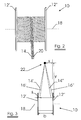
- FIGURE 1 shows a spool 10 according to a first embodiment of the first aspect of the present invention.
- the spool 10 is provided with two flanges 12' and 12".
- Two steel cords 14 and 16 both twisted in S-direction, are wound in parallel and adjacent to each other on spool 10.
- the distance s, as measured along a line parallel to the axis 18 of spool 10, is less than 5 mm.
- FIGURE 2 shows a spool 10 according to a particular and second embodiment of the first aspect of the present invention.
- the spool 10 is provided with two flanges 12' and 12".
- a steel cord 14, twisted in S-direction, and a steel cord 20, twisted in Z-direction, are wound in parallel and adjacent to each other on spool 10.
- the distance s, as measured along a line parallel to the axis 18 of spool 10, is less than 5 mm.
- any residual torsions present on S-cords may compensate on average any residual torsions present on Z-cords so that eventually cut composite strips rubber - steel cord do not exhibit curling.
- residual torsions are defined as follows : if one end of a specified length of cord is allowed to turn freely, the number of residual torsions is equal to the number of revolutions counted.
- An imbalance of residual torsions over the totality of steel cords within one composite strip rubber - steel cord is known as the main cause of curling. Avoiding this imbalance reduces the risk for curling. And, as explained above, avoidance of curling may facilitate the automated handling of the strips. In such configuration it is sufficient that the steel cords present in the cut strips have on average no residual torsions. As a result it is no longer required to fine-tune the amount of residual torsions present on each single steel cord during its twisting step. This may considerably reduce the auxiliary equipment required, more particularly, the automatic torsion control may be cancelled.
- FIGURE 3 explains the basic working of the present invention.
- Spool 10 is filled with two steel cords 14, 16. There is a distance s present between the two steel cords 14 and 16, measured along a line parallel to the axis 18 of the spool 10.
- the two steel cords 14, 16 are wound from spool 10 and are guided through one single fixed hole 22.
- Steel cords 14' and 16' show the situation at the left flange 12' and steel cords 14" and 16" show the situation at the right flange 12".
- the distance s is supposed to remain constant during the unwinding process.
- the spool width b is equal to 153 mm.
- the steel cord is of a 2x0.30 type, so that the cross-section A is equal to 0.141372 mm 2 .
- l 1 is the length of the unwound cord 14'.
- l 2 the length of the unwound cord 16'
- l 3 the length of the unwound cord 14"
- l 4 the length of the unwound cord 16".
- the underlying layer consisting of the same type of elongated elements, the underlying layer is rough. So it is not always possible to keep the distance s constant during winding. Nevertheless measures should be taken to keep the distance between the neighboring elongated elements as small as possible.
Landscapes
- Ropes Or Cables (AREA)
- Storage Of Web-Like Or Filamentary Materials (AREA)
- Joining Of Building Structures In Genera (AREA)
- Iron Core Of Rotating Electric Machines (AREA)
- Unwinding Of Filamentary Materials (AREA)
- Filamentary Materials, Packages, And Safety Devices Therefor (AREA)
- Winding Filamentary Materials (AREA)
- Guides For Winding Or Rewinding, Or Guides For Filamentary Materials (AREA)
Claims (10)
- Bobine remplie de deux éléments d'acier allongés, ou plus, enroulés en parallèle et en plusieurs enroulements autour de ladite bobine, caractérisée en ce que la distance entre deux éléments d'acier allongés voisins, mesurée le long d'une ligne parallèle à l'axe de la bobine, n'est pas supérieure à 10 mm sur 90 % de la longueur de chaque élément d'acier allongé.
- Bobine selon la revendication 1, dans laquelle ladite distance est inférieure à 5 mm.
- Bobine selon la revendication 1, dans laquelle lesdits éléments d'acier sont des fils d'acier.
- Bobine selon la revendication 1, dans laquelle lesdits éléments d'acier sont des câbles d'acier.
- Bobine selon la revendication 4, dans laquelle un desdits câbles d'acier comprend des filaments d'acier, une majorité de ceux-ci étant torsadés dans une première direction de torsion, et dans laquelle un autre desdits câbles d'acier comprend des filaments d'acier, une majorité de ceux-ci étant torsadés dans une deuxième direction de torsion, ladite deuxième direction de torsion étant opposée à ladite première direction de torsion.
- Procédé pour minimiser les gauchissements lors du débobinage de multiples éléments d'acier allongés à partir d'une seule bobine, ledit procédé comprenant les étapes suivantes:a) fournir une bobine; etb) enrouler de multiples éléments d'acier allongés en parallèle et en plusieurs enroulements autour de ladite bobine de telle sorte que la distance entre deux éléments d'acier allongés voisins, mesurée le long d'une ligne parallèle à l'axe de la bobine, n'est pas supérieure à 10 mm sur 90 % de la longueur de chaque élément d'acier allongé.
- Procédé selon la revendication 6, dans lequel ledit procédé comprend en outre l'étape suivante:- guider les multiples éléments d'acier allongés sur une poulie commune en amont de la bobine.
- Procédé selon la revendication 7, dans lequel ledit procédé comprend en outre l'étape suivante:- maintenir les multiples éléments d'acier allongés séparés les uns des autres en amont de ladite poulie commune.
- Procédé selon la revendication 8, dans lequel ladite poulie commune comporte une rainure plate.
- Procédé selon la revendication 9, dans lequel la largeur de ladite rainure plate est supérieure à la somme des diamètres des multiples éléments allongés.
Priority Applications (1)
| Application Number | Priority Date | Filing Date | Title |
|---|---|---|---|
| EP02792875A EP1485314B1 (fr) | 2002-03-13 | 2002-12-03 | Bobine remplie de multiples elements allonges enroules de facon rapprochee |
Applications Claiming Priority (4)
| Application Number | Priority Date | Filing Date | Title |
|---|---|---|---|
| EP02100243 | 2002-03-13 | ||
| EP02100243 | 2002-03-13 | ||
| EP02792875A EP1485314B1 (fr) | 2002-03-13 | 2002-12-03 | Bobine remplie de multiples elements allonges enroules de facon rapprochee |
| PCT/EP2002/013688 WO2003076321A1 (fr) | 2002-03-13 | 2002-12-03 | Bobine remplie de multiples elements allonges enroules de facon rapprochee |
Publications (2)
| Publication Number | Publication Date |
|---|---|
| EP1485314A1 EP1485314A1 (fr) | 2004-12-15 |
| EP1485314B1 true EP1485314B1 (fr) | 2006-10-18 |
Family
ID=27798897
Family Applications (1)
| Application Number | Title | Priority Date | Filing Date |
|---|---|---|---|
| EP02792875A Expired - Lifetime EP1485314B1 (fr) | 2002-03-13 | 2002-12-03 | Bobine remplie de multiples elements allonges enroules de facon rapprochee |
Country Status (12)
| Country | Link |
|---|---|
| US (1) | US7185838B2 (fr) |
| EP (1) | EP1485314B1 (fr) |
| JP (1) | JP2005519827A (fr) |
| KR (1) | KR20040089614A (fr) |
| CN (1) | CN1289372C (fr) |
| AT (1) | ATE342861T1 (fr) |
| AU (1) | AU2002358591A1 (fr) |
| DE (1) | DE60215553T2 (fr) |
| EA (1) | EA005968B1 (fr) |
| ES (1) | ES2272804T3 (fr) |
| PT (1) | PT1485314E (fr) |
| WO (1) | WO2003076321A1 (fr) |
Families Citing this family (17)
| Publication number | Priority date | Publication date | Assignee | Title |
|---|---|---|---|---|
| US8800967B2 (en) | 2009-03-23 | 2014-08-12 | Southwire Company, Llc | Integrated systems facilitating wire and cable installations |
| US9802785B2 (en) | 2008-01-21 | 2017-10-31 | Southwire Company, Llc | Systems and methods for facilitating wire and cable installations |
| US10003179B2 (en) | 2008-01-21 | 2018-06-19 | Southwire Company, Llc | Integrated systems facilitating wire and cable installations |
| GB0818922D0 (en) | 2008-10-16 | 2008-11-19 | Otv Sa | Component, method and system of sanitising a water purification apparatus and/or a distribution apparatus |
| ITRN20080057A1 (it) * | 2008-12-04 | 2009-03-05 | Lisciani Trafilerie Srl R | Bobina di erogazione di fili di ferro per legature |
| US8936153B1 (en) | 2011-05-04 | 2015-01-20 | Southwire Company, Llc | Multiple conductor container |
| US9079370B2 (en) * | 2011-07-21 | 2015-07-14 | Adc Telecommunications, Inc. | Method for extruding a drop cable |
| US9027908B1 (en) | 2011-09-01 | 2015-05-12 | Southwire Company, Llc | Field-installable pulling eye |
| US10232868B1 (en) | 2012-05-04 | 2019-03-19 | Southwire Company, Llc | Container for storing conductors |
| US9867300B1 (en) | 2012-05-04 | 2018-01-09 | Southwire Company, Llc | Multiple conductor container |
| CN104338873A (zh) | 2013-07-29 | 2015-02-11 | 贝卡尔特公司 | 用于带束层上的直的单丝 |
| CN104787618A (zh) * | 2015-04-20 | 2015-07-22 | 江苏胜达科技有限公司 | 废丝处理装置 |
| PT3326921T (pt) | 2015-07-22 | 2022-09-12 | Max Co Ltd | Máquina de amarração |
| CA2941006C (fr) | 2015-09-01 | 2024-01-16 | Southwire Company, Llc | Identification de conducteur |
| GB2562458A (en) | 2017-03-17 | 2018-11-21 | Vws Uk Ltd | Method for providing ultrapure water |
| CN107444994B (zh) * | 2017-07-25 | 2023-08-01 | 杭州舜海光伏科技有限公司 | 收放绳装置及清扫设备 |
| CN111942959A (zh) * | 2020-07-20 | 2020-11-17 | 陕西天元智能再制造股份有限公司 | 一种并排双头缠绕盘装焊丝及其制备方法与用途 |
Family Cites Families (9)
| Publication number | Priority date | Publication date | Assignee | Title |
|---|---|---|---|---|
| US2187841A (en) * | 1935-11-29 | 1940-01-23 | Nat Standard Co | Wire winding apparatus |
| GB1163983A (en) * | 1967-03-28 | 1969-09-10 | Bekaert Pvba Leon | Improvements relating to the Winding of Strand Material |
| US4488686A (en) * | 1983-01-10 | 1984-12-18 | Ppg Industries, Inc. | Apparatus and method for packaging a plurality of filaments or bundles of filaments |
| JPS61186585A (ja) * | 1985-02-12 | 1986-08-20 | 住友電気工業株式会社 | ボビン巻スチ−ルコ−ド |
| JPS6362467A (ja) * | 1986-09-03 | 1988-03-18 | Matsushita Graphic Commun Syst Inc | フアクシミリ手順方法 |
| JPS6424047A (en) * | 1987-07-17 | 1989-01-26 | Nitto Glass Fiber Mfg | Production of glass yarn |
| JPH04308166A (ja) * | 1991-04-05 | 1992-10-30 | Nippondenso Co Ltd | 巻線機用ガイド装置 |
| EP0780333A1 (fr) * | 1995-12-18 | 1997-06-25 | N.V. Bekaert S.A. | Bobinage de plusieurs fils |
| TW200636771A (en) * | 2005-03-03 | 2006-10-16 | Nittoku Eng | Multilayer coil, winding method of same, and winding apparatus of same |
-
2002
- 2002-12-03 DE DE60215553T patent/DE60215553T2/de not_active Expired - Lifetime
- 2002-12-03 AT AT02792875T patent/ATE342861T1/de not_active IP Right Cessation
- 2002-12-03 EP EP02792875A patent/EP1485314B1/fr not_active Expired - Lifetime
- 2002-12-03 PT PT02792875T patent/PT1485314E/pt unknown
- 2002-12-03 WO PCT/EP2002/013688 patent/WO2003076321A1/fr not_active Ceased
- 2002-12-03 CN CNB028284259A patent/CN1289372C/zh not_active Expired - Lifetime
- 2002-12-03 KR KR10-2004-7012400A patent/KR20040089614A/ko not_active Ceased
- 2002-12-03 ES ES02792875T patent/ES2272804T3/es not_active Expired - Lifetime
- 2002-12-03 EA EA200401196A patent/EA005968B1/ru not_active IP Right Cessation
- 2002-12-03 AU AU2002358591A patent/AU2002358591A1/en not_active Abandoned
- 2002-12-03 US US10/507,503 patent/US7185838B2/en not_active Expired - Lifetime
- 2002-12-03 JP JP2003574552A patent/JP2005519827A/ja active Pending
Also Published As
| Publication number | Publication date |
|---|---|
| ATE342861T1 (de) | 2006-11-15 |
| DE60215553T2 (de) | 2007-06-06 |
| AU2002358591A1 (en) | 2003-09-22 |
| JP2005519827A (ja) | 2005-07-07 |
| CN1622913A (zh) | 2005-06-01 |
| WO2003076321A1 (fr) | 2003-09-18 |
| EP1485314A1 (fr) | 2004-12-15 |
| DE60215553D1 (de) | 2006-11-30 |
| US20050139706A1 (en) | 2005-06-30 |
| EA200401196A1 (ru) | 2005-02-24 |
| PT1485314E (pt) | 2007-01-31 |
| CN1289372C (zh) | 2006-12-13 |
| US7185838B2 (en) | 2007-03-06 |
| ES2272804T3 (es) | 2007-05-01 |
| EA005968B1 (ru) | 2005-08-25 |
| KR20040089614A (ko) | 2004-10-21 |
Similar Documents
| Publication | Publication Date | Title |
|---|---|---|
| EP1485314B1 (fr) | Bobine remplie de multiples elements allonges enroules de facon rapprochee | |
| CN101680133B (zh) | 合股细丝的方法及采用该方法制造的细丝束 | |
| KR102199539B1 (ko) | 벨트 플라이를 위한 직선형 강철 모노필라멘트 | |
| EP0143732B1 (fr) | Dispositif et procédé pour la fabrication d'une corde métallique | |
| EP0780333A1 (fr) | Bobinage de plusieurs fils | |
| JP5254887B2 (ja) | 線材の巻取り装置および巻取り方法 | |
| JP4666555B2 (ja) | 鋼線の複数本束巻き取り方法 | |
| JP2008025040A (ja) | スチールコード及びその製造方法 | |
| JPS58128238A (ja) | ビ−ドリングの製造方法 | |
| JP3197604B2 (ja) | 線材入りゴムシートの製造方法 | |
| JP2596348Y2 (ja) | 撚線機における矯正装置 | |
| JP2568454Y2 (ja) | ゴム補強用スチールコード | |
| JP2009235640A (ja) | スチールコードおよびこのスチールコードで構成されたスチールコード群 | |
| KR200190508Y1 (ko) | 스틸코드 연선기의 와이어 이탈 방지 장치 | |
| JPS6211936B2 (fr) | ||
| JP5623105B2 (ja) | スチールコードの製造方法 | |
| EP4642723A1 (fr) | Procédé et configuration pour raccorder des ensembles stratifils | |
| CN119301323A (zh) | 具有可更换线轴载体的捻线机 | |
| JP2013209769A (ja) | スチールコードの製造方法、およびそれにより得られたスチールコード | |
| JPH1025678A (ja) | ゴム製品補強用スチールコードおよびその製造設備と空気入りラジアルタイヤ | |
| JPH07166484A (ja) | ゴム物品補強用スチ−ルコ−ド及びその複合体 |
Legal Events
| Date | Code | Title | Description |
|---|---|---|---|
| PUAI | Public reference made under article 153(3) epc to a published international application that has entered the european phase |
Free format text: ORIGINAL CODE: 0009012 |
|
| 17P | Request for examination filed |
Effective date: 20040827 |
|
| AK | Designated contracting states |
Kind code of ref document: A1 Designated state(s): AT BE BG CH CY CZ DE DK EE ES FI FR GB GR IE IT LI LU MC NL PT SE SI SK TR |
|
| AX | Request for extension of the european patent |
Extension state: AL LT LV MK RO |
|
| RIN1 | Information on inventor provided before grant (corrected) |
Inventor name: VANNESTE, STIJN Inventor name: MULLEBROUCK, RIK Inventor name: SABBE, LUC |
|
| GRAP | Despatch of communication of intention to grant a patent |
Free format text: ORIGINAL CODE: EPIDOSNIGR1 |
|
| GRAS | Grant fee paid |
Free format text: ORIGINAL CODE: EPIDOSNIGR3 |
|
| GRAA | (expected) grant |
Free format text: ORIGINAL CODE: 0009210 |
|
| AK | Designated contracting states |
Kind code of ref document: B1 Designated state(s): AT BE BG CH CY CZ DE DK EE ES FI FR GB GR IE IT LI LU MC NL PT SE SI SK TR |
|
| PG25 | Lapsed in a contracting state [announced via postgrant information from national office to epo] |
Ref country code: LI Free format text: LAPSE BECAUSE OF FAILURE TO SUBMIT A TRANSLATION OF THE DESCRIPTION OR TO PAY THE FEE WITHIN THE PRESCRIBED TIME-LIMIT Effective date: 20061018 Ref country code: CH Free format text: LAPSE BECAUSE OF FAILURE TO SUBMIT A TRANSLATION OF THE DESCRIPTION OR TO PAY THE FEE WITHIN THE PRESCRIBED TIME-LIMIT Effective date: 20061018 Ref country code: AT Free format text: LAPSE BECAUSE OF FAILURE TO SUBMIT A TRANSLATION OF THE DESCRIPTION OR TO PAY THE FEE WITHIN THE PRESCRIBED TIME-LIMIT Effective date: 20061018 Ref country code: SI Free format text: LAPSE BECAUSE OF FAILURE TO SUBMIT A TRANSLATION OF THE DESCRIPTION OR TO PAY THE FEE WITHIN THE PRESCRIBED TIME-LIMIT Effective date: 20061018 |
|
| REG | Reference to a national code |
Ref country code: GB Ref legal event code: FG4D |
|
| REG | Reference to a national code |
Ref country code: CH Ref legal event code: EP Ref country code: IE Ref legal event code: FG4D |
|
| PGFP | Annual fee paid to national office [announced via postgrant information from national office to epo] |
Ref country code: BE Payment date: 20061123 Year of fee payment: 5 Ref country code: GB Payment date: 20061123 Year of fee payment: 5 |
|
| REF | Corresponds to: |
Ref document number: 60215553 Country of ref document: DE Date of ref document: 20061130 Kind code of ref document: P |
|
| PG25 | Lapsed in a contracting state [announced via postgrant information from national office to epo] |
Ref country code: IE Free format text: LAPSE BECAUSE OF NON-PAYMENT OF DUE FEES Effective date: 20061204 |
|
| PGFP | Annual fee paid to national office [announced via postgrant information from national office to epo] |
Ref country code: BG Payment date: 20061215 Year of fee payment: 5 |
|
| PG25 | Lapsed in a contracting state [announced via postgrant information from national office to epo] |
Ref country code: MC Free format text: LAPSE BECAUSE OF NON-PAYMENT OF DUE FEES Effective date: 20061231 |
|
| PG25 | Lapsed in a contracting state [announced via postgrant information from national office to epo] |
Ref country code: SE Free format text: LAPSE BECAUSE OF FAILURE TO SUBMIT A TRANSLATION OF THE DESCRIPTION OR TO PAY THE FEE WITHIN THE PRESCRIBED TIME-LIMIT Effective date: 20070118 Ref country code: DK Free format text: LAPSE BECAUSE OF FAILURE TO SUBMIT A TRANSLATION OF THE DESCRIPTION OR TO PAY THE FEE WITHIN THE PRESCRIBED TIME-LIMIT Effective date: 20070118 |
|
| REG | Reference to a national code |
Ref country code: PT Ref legal event code: SC4A Free format text: AVAILABILITY OF NATIONAL TRANSLATION Effective date: 20061205 |
|
| ET | Fr: translation filed | ||
| REG | Reference to a national code |
Ref country code: CH Ref legal event code: PL |
|
| REG | Reference to a national code |
Ref country code: ES Ref legal event code: FG2A Ref document number: 2272804 Country of ref document: ES Kind code of ref document: T3 |
|
| PLBE | No opposition filed within time limit |
Free format text: ORIGINAL CODE: 0009261 |
|
| STAA | Information on the status of an ep patent application or granted ep patent |
Free format text: STATUS: NO OPPOSITION FILED WITHIN TIME LIMIT |
|
| 26N | No opposition filed |
Effective date: 20070719 |
|
| PG25 | Lapsed in a contracting state [announced via postgrant information from national office to epo] |
Ref country code: GR Free format text: LAPSE BECAUSE OF FAILURE TO SUBMIT A TRANSLATION OF THE DESCRIPTION OR TO PAY THE FEE WITHIN THE PRESCRIBED TIME-LIMIT Effective date: 20070119 |
|
| BERE | Be: lapsed |
Owner name: N.V. BEKAERT S.A. Effective date: 20071231 |
|
| PG25 | Lapsed in a contracting state [announced via postgrant information from national office to epo] |
Ref country code: EE Free format text: LAPSE BECAUSE OF FAILURE TO SUBMIT A TRANSLATION OF THE DESCRIPTION OR TO PAY THE FEE WITHIN THE PRESCRIBED TIME-LIMIT Effective date: 20061018 |
|
| GBPC | Gb: european patent ceased through non-payment of renewal fee |
Effective date: 20071203 |
|
| PG25 | Lapsed in a contracting state [announced via postgrant information from national office to epo] |
Ref country code: BE Free format text: LAPSE BECAUSE OF NON-PAYMENT OF DUE FEES Effective date: 20071231 |
|
| PG25 | Lapsed in a contracting state [announced via postgrant information from national office to epo] |
Ref country code: BG Free format text: LAPSE BECAUSE OF NON-PAYMENT OF DUE FEES Effective date: 20080630 |
|
| PG25 | Lapsed in a contracting state [announced via postgrant information from national office to epo] |
Ref country code: CY Free format text: LAPSE BECAUSE OF FAILURE TO SUBMIT A TRANSLATION OF THE DESCRIPTION OR TO PAY THE FEE WITHIN THE PRESCRIBED TIME-LIMIT Effective date: 20061018 |
|
| PG25 | Lapsed in a contracting state [announced via postgrant information from national office to epo] |
Ref country code: GB Free format text: LAPSE BECAUSE OF NON-PAYMENT OF DUE FEES Effective date: 20071203 |
|
| PGFP | Annual fee paid to national office [announced via postgrant information from national office to epo] |
Ref country code: CZ Payment date: 20081124 Year of fee payment: 7 Ref country code: NL Payment date: 20081223 Year of fee payment: 7 |
|
| PGFP | Annual fee paid to national office [announced via postgrant information from national office to epo] |
Ref country code: FI Payment date: 20081230 Year of fee payment: 7 Ref country code: PT Payment date: 20081125 Year of fee payment: 7 |
|
| REG | Reference to a national code |
Ref country code: PT Ref legal event code: MM4A Free format text: LAPSE DUE TO NON-PAYMENT OF FEES Effective date: 20100604 |
|
| REG | Reference to a national code |
Ref country code: NL Ref legal event code: V1 Effective date: 20100701 |
|
| PG25 | Lapsed in a contracting state [announced via postgrant information from national office to epo] |
Ref country code: PT Free format text: LAPSE BECAUSE OF NON-PAYMENT OF DUE FEES Effective date: 20100604 |
|
| PG25 | Lapsed in a contracting state [announced via postgrant information from national office to epo] |
Ref country code: FI Free format text: LAPSE BECAUSE OF NON-PAYMENT OF DUE FEES Effective date: 20091203 Ref country code: CZ Free format text: LAPSE BECAUSE OF NON-PAYMENT OF DUE FEES Effective date: 20091203 |
|
| PG25 | Lapsed in a contracting state [announced via postgrant information from national office to epo] |
Ref country code: NL Free format text: LAPSE BECAUSE OF NON-PAYMENT OF DUE FEES Effective date: 20100701 |
|
| REG | Reference to a national code |
Ref country code: FR Ref legal event code: PLFP Year of fee payment: 14 |
|
| REG | Reference to a national code |
Ref country code: FR Ref legal event code: PLFP Year of fee payment: 15 |
|
| REG | Reference to a national code |
Ref country code: FR Ref legal event code: PLFP Year of fee payment: 16 |
|
| PGFP | Annual fee paid to national office [announced via postgrant information from national office to epo] |
Ref country code: LU Payment date: 20191219 Year of fee payment: 18 |
|
| PG25 | Lapsed in a contracting state [announced via postgrant information from national office to epo] |
Ref country code: LU Free format text: LAPSE BECAUSE OF NON-PAYMENT OF DUE FEES Effective date: 20201203 |
|
| PGFP | Annual fee paid to national office [announced via postgrant information from national office to epo] |
Ref country code: FR Payment date: 20211224 Year of fee payment: 20 Ref country code: DE Payment date: 20211210 Year of fee payment: 20 Ref country code: SK Payment date: 20211202 Year of fee payment: 20 Ref country code: TR Payment date: 20211202 Year of fee payment: 20 |
|
| PGFP | Annual fee paid to national office [announced via postgrant information from national office to epo] |
Ref country code: IT Payment date: 20211224 Year of fee payment: 20 Ref country code: ES Payment date: 20220218 Year of fee payment: 20 |
|
| REG | Reference to a national code |
Ref country code: DE Ref legal event code: R071 Ref document number: 60215553 Country of ref document: DE |
|
| REG | Reference to a national code |
Ref country code: SK Ref legal event code: MK4A Ref document number: E 1334 Country of ref document: SK Expiry date: 20221203 |
|
| PG25 | Lapsed in a contracting state [announced via postgrant information from national office to epo] |
Ref country code: SK Free format text: LAPSE BECAUSE OF EXPIRATION OF PROTECTION Effective date: 20221203 |
|
| REG | Reference to a national code |
Ref country code: ES Ref legal event code: FD2A Effective date: 20230428 |
|
| PG25 | Lapsed in a contracting state [announced via postgrant information from national office to epo] |
Ref country code: ES Free format text: LAPSE BECAUSE OF EXPIRATION OF PROTECTION Effective date: 20221204 |