EP1486382A2 - Procédé et dispositif de détection de retournement de véhicule - Google Patents
Procédé et dispositif de détection de retournement de véhicule Download PDFInfo
- Publication number
- EP1486382A2 EP1486382A2 EP04252883A EP04252883A EP1486382A2 EP 1486382 A2 EP1486382 A2 EP 1486382A2 EP 04252883 A EP04252883 A EP 04252883A EP 04252883 A EP04252883 A EP 04252883A EP 1486382 A2 EP1486382 A2 EP 1486382A2
- Authority
- EP
- European Patent Office
- Prior art keywords
- vehicle
- threshold
- actual
- roll angle
- rollover
- Prior art date
- Legal status (The legal status is an assumption and is not a legal conclusion. Google has not performed a legal analysis and makes no representation as to the accuracy of the status listed.)
- Granted
Links
Images


Classifications
-
- B—PERFORMING OPERATIONS; TRANSPORTING
- B60—VEHICLES IN GENERAL
- B60R—VEHICLES, VEHICLE FITTINGS, OR VEHICLE PARTS, NOT OTHERWISE PROVIDED FOR
- B60R21/00—Arrangements or fittings on vehicles for protecting or preventing injuries to occupants or pedestrians in case of accidents or other traffic risks
- B60R21/01—Electrical circuits for triggering passive safety arrangements, e.g. airbags, safety belt tighteners, in case of vehicle accidents or impending vehicle accidents
- B60R21/013—Electrical circuits for triggering passive safety arrangements, e.g. airbags, safety belt tighteners, in case of vehicle accidents or impending vehicle accidents including means for detecting collisions, impending collisions or roll-over
- B60R21/0132—Electrical circuits for triggering passive safety arrangements, e.g. airbags, safety belt tighteners, in case of vehicle accidents or impending vehicle accidents including means for detecting collisions, impending collisions or roll-over responsive to vehicle motion parameters, e.g. to vehicle longitudinal or transversal deceleration or speed value
-
- B—PERFORMING OPERATIONS; TRANSPORTING
- B60—VEHICLES IN GENERAL
- B60R—VEHICLES, VEHICLE FITTINGS, OR VEHICLE PARTS, NOT OTHERWISE PROVIDED FOR
- B60R21/00—Arrangements or fittings on vehicles for protecting or preventing injuries to occupants or pedestrians in case of accidents or other traffic risks
- B60R21/01—Electrical circuits for triggering passive safety arrangements, e.g. airbags, safety belt tighteners, in case of vehicle accidents or impending vehicle accidents
- B60R21/013—Electrical circuits for triggering passive safety arrangements, e.g. airbags, safety belt tighteners, in case of vehicle accidents or impending vehicle accidents including means for detecting collisions, impending collisions or roll-over
- B60R21/0132—Electrical circuits for triggering passive safety arrangements, e.g. airbags, safety belt tighteners, in case of vehicle accidents or impending vehicle accidents including means for detecting collisions, impending collisions or roll-over responsive to vehicle motion parameters, e.g. to vehicle longitudinal or transversal deceleration or speed value
- B60R2021/01322—Electrical circuits for triggering passive safety arrangements, e.g. airbags, safety belt tighteners, in case of vehicle accidents or impending vehicle accidents including means for detecting collisions, impending collisions or roll-over responsive to vehicle motion parameters, e.g. to vehicle longitudinal or transversal deceleration or speed value comprising variable thresholds, e.g. depending from other collision parameters
-
- B—PERFORMING OPERATIONS; TRANSPORTING
- B60—VEHICLES IN GENERAL
- B60R—VEHICLES, VEHICLE FITTINGS, OR VEHICLE PARTS, NOT OTHERWISE PROVIDED FOR
- B60R21/00—Arrangements or fittings on vehicles for protecting or preventing injuries to occupants or pedestrians in case of accidents or other traffic risks
- B60R21/01—Electrical circuits for triggering passive safety arrangements, e.g. airbags, safety belt tighteners, in case of vehicle accidents or impending vehicle accidents
- B60R21/013—Electrical circuits for triggering passive safety arrangements, e.g. airbags, safety belt tighteners, in case of vehicle accidents or impending vehicle accidents including means for detecting collisions, impending collisions or roll-over
- B60R21/0132—Electrical circuits for triggering passive safety arrangements, e.g. airbags, safety belt tighteners, in case of vehicle accidents or impending vehicle accidents including means for detecting collisions, impending collisions or roll-over responsive to vehicle motion parameters, e.g. to vehicle longitudinal or transversal deceleration or speed value
- B60R2021/01327—Angular velocity or angular acceleration
Definitions
- the present invention relates to a method and apparatus for detecting the possibility of rollover of a vehicle based on a roll angular velocity and a roll angle of the vehicle.
- Japanese Laid-Open Patent Publication No. 2001-260786 proposes vehicle rollover detection technique, in which it is judged that there is a possibility that a vehicle rolls over when the plot of an actual roll angular velocity and an actual roll angle of the vehicle on a two-dimensional map crosses a threshold line.
- the threshold line is set on the map with reference to normal usage conditions of the vehicle.
- the actual usage conditions of the vehicle are not limited to the normal vehicle usage conditions, and vary depending on such arbitrary parameters as the number of occupants in the vehicle and the weight and position of a load on the vehicle.
- the vehicle characteristics including the height of the center of gravity of the vehicle become changed in accordance with the actual vehicle usage conditions.
- the vehicle characteristics may also be changed due to e.g. a decrease in elasticity (a permanent set in fatigue) of vehicle suspensions with years of use.
- the rollover judgment threshold line is not adjusted in response to these changes in the vehicle characteristics, thereby occasionally failing to provide an optimum vehicle rollover judgment.
- a method for detecting the possibility of rollover of a vehicle comprising: detecting an actual roll angular velocity of the vehicle; obtaining an actual roll angle of the vehicle; determining an actual lateral acceleration of the vehicle; providing a two-dimensional map correlating values of the roll angular velocity with values of the roll angle to define a rollover judgment threshold; changing the threshold based on the actual roll angle and the actual lateral acceleration; forming a plot of the actual roll angular velocity versus the actual roll angle on the two-dimensional map; and judging that there is a possibility that the vehicle rolls over when the plot exceeds the threshold.
- an apparatus for detecting the possibility of rollover of a vehicle comprising: means for detecting an actual roll angular velocity of the vehicle; means for obtaining an actual roll angle of the vehicle; means for determining an actual lateral acceleration of the vehicle; means for providing a two-dimensional map correlating values of the roll angular velocity with values of the roll angle to define a rollover judgment threshold; means for changing the threshold based on the actual roll angle and the actual lateral acceleration; means for forming a plot of the actual roll angular velocity versus the actual roll angle on the two-dimensional map; and means for judging that there is a possibility that the vehicle rolls over when the plot exceeds the threshold
- an apparatus for detecting the possibility of rollover of a vehicle comprising: a rate sensor to detect an actual roll angular velocity of the vehicle; and a controller connected to the rate sensor to read the actual roll angular velocity and storing therein a roll angular velocity versus roll angle map, the roll angular velocity versus roll angle map having threshold lines in first and third quadrants of the map to define rollover ranges on farther sides of the threshold lines from an origin of the map, the controller being configured to: calculate an actual roll angle of the vehicle from the actual roll angular velocity; determine an actual lateral acceleration of the vehicle; calculate a threshold change factor from the actual roll angle and the actual lateral acceleration; change the threshold lines with reference to the threshold change factor so as to adjust the rollover ranges; form a plot of the actual roll angular velocity versus the actual roll angle on the map; and judge the possibility of rollover of the vehicle when the plot falls within either of the rollover ranges.
- FIG. 1 is a schematic view of a vehicle rollover detection apparatus according to one embodiment of the present invention.
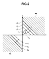
- FIG. 2 is a two-dimensional map used for judging the possibility of rollover of a vehicle according to one embodiment of the present invention.
- FIG. 3 is a schematic view for explaining how the vehicle rolls over.
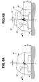
- FIGS. 4A and 4B are schematic views for explaining how vehicle roll behavior becomes changed in accordance with vehicle usage conditions.
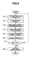
- FIG. 5 is a flowchart for detecting the possibility of rollover of the vehicle according to one embodiment of the present invention.
- vehicle rollover detection apparatus 1 for detecting the possibility of rollover of vehicle 61 in one exemplary embodiment of the present invention.
- vehicle rollover detection apparatus 1 includes rate sensor 10 to detect an angular velocity ⁇ of rotation of vehicle 61 about a vehicle forward/reverse traveling direction (hereinafter referred to as a "roll angular velocity”), vehicle speed sensor 20 to detect a traveling speed V of vehicle 61 (hereinafter just referred to as a "vehicle speed”), steering angle sensor 30 to detect a steering angle ⁇ of vehicle 61 through a steering wheel (not shown), and controller 40 to judge whether or not there is a possibility that vehicle 61 rolls over based on the roll angular velocity ⁇ and roll angle ⁇ of vehicle 61 and to control safety system 50 upon the vehicle rollover judgment.
- rate sensor 10 to detect an angular velocity ⁇ of rotation of vehicle 61 about a vehicle forward/reverse traveling direction (hereinafter referred to as a "roll angular velocity")
- vehicle speed sensor 20 to detect a traveling speed V of vehicle 61 (hereinafter just referred to as a "vehicle speed”)
- steering angle sensor 30 to detect
- Rate sensor 10, vehicle speed sensor 20, and steering angle sensor 30 are connected to controller 40 so that controller 40 receives input about the roll angular velocity ⁇ , vehicle speed V, and steering angle ⁇ via rate sensor 10, vehicle speed sensor 20,and steering angle sensor 30, respectively.
- Safety system 50 has a curtain air bag with an inflator and/or a seat belt with a pretensioner connected with controller 40, such that safety system 50 is operated under the control of an actuation signal from controller 40.
- Controller 40 is generally comprised of a CPU, a ROM, and a RAM, and stores therein a two-dimensional map correlating values of the roll angular velocity ⁇ with values of the roll angle ⁇ to define threshold S for judging the possibility of rollover of vehicle 61.
- the rollover judgment threshold S is initially represented by two reference threshold lines S 0 in the first and third quadrants of the roll angular velocity versus roll angle map so as to form two rollover ranges RA on the sides of the threshold lines S 0 farther from an origin of the map in the first and third quadrants as shown in FIG. 2.
- the reference threshold lines S 0 are set on the basis of the characteristics of vehicle 61 under normal usage conditions in terms of the number of occupants 62, the weight,and position of load 63, and the like.
- vehicle 61 undergoes a given level of lateral acceleration G and rolls at a roll angle ⁇ 0 (hereinafter referred to as a "reference roll angle") while turning around at constant steady speed V, as shown in FIG. 4A, and the center of gravity gv of vehicle 61 is positioned at a height h 0 (hereinafter referred to a "reference height”) relative to the ground.
- controller 40 includes roll angle calculating section 41, lateral acceleration calculating section 42, threshold change factor calculating section 43,and rollover judging section 44.
- Roll angle calculating section 41 is connected with rate sensor 10 to read the actual roll angular velocity ⁇ from rate sensor 10, and is programmed to calculate the actual roll angle ⁇ from the actual roll angular velocity ⁇ .
- the actual roll angle ⁇ is obtained by integrating the actual roll angular velocity ⁇ .
- roll angle calculating section 41 is connected with threshold change factor calculating section 43 to output the actual roll angle ⁇ to threshold change factor calculating section 43 and, at the same time, is connected with rollover judging section 44 to output the actual roll angle ⁇ as well as the actual roll angular velocity ⁇ to rollover judging section 44.
- high-pass filter (HPC) 10a is provided between rate sensor 10 and roll angle calculating section 41.
- Lateral acceleration calculating section 42 is connected with vehicle speed sensor 20 and steering angle sensor 30 to read the vehicle speed V and steering angle ⁇ from vehicle speed sensor 20 and steering angle sensor 30, respectively, and is programmed to calculate the lateral acceleration G actually acting on vehicle 61 from the vehicle speed V and steering angle ⁇ .
- the lateral acceleration G is determined by estimating a lateral vehicle speed V X (i.e., a component of vehicle speed V in a direction laterally perpendicular to the vehicle forward/reverse traveling direction) from the vehicle speed V and steering angle ⁇ and differentiating the lateral vehicle speed V X .
- lateral acceleration calculating section 42 may be programmed to calculate the actual lateral acceleration G only when the steering angle ⁇ is equal to or larger than a given degree, so as to avoid a calculation error that can occur in straight-ahead traveling where both of the lateral acceleration and lateral inclination angle of vehicle 61 are small and to thereby improve the accuracy of the vehicle rollover judgment.
- the lateral acceleration G is determined based on the outputs from vehicle speed sensor 20 and steering angle sensor 30 that are provided for other intended uses in the present embodiment. It is thus possible to provide vehicle rollover detection apparatus 1 at a lower cost.
- Threshold change factor calculating section 43 is connected with roll angle calculating section 41 and lateral acceleration calculating section 42 to read the actual roll angle value ⁇ and lateral acceleration G from roll angle calculating section 41 and lateral acceleration calculating section 42, respectively, and is programmed to calculate a threshold change factor ⁇ from the actual roll angle ⁇ and lateral acceleration G in order to change the rollover judgment threshold S and thereby adjust the rollover ranges RA in accordance the vehicle characteristics conforming to the actual usage conditions of vehicle 61.
- the rollover of vehicle 61 occurs at the time the rolling energy (rotational kinetic energy) of vehicle 61 becomes larger than the potential energy of vehicle 61 corresponding to a difference H between the initial height and the maximum possible height of the center of gravity gv of vehicle 61 as shown in FIG. 3.
- the rollover of vehicle 61 occurs at the time the following equation is satisfied: 1 2 m ⁇ 2 > mgH where m is the mass of vehicle 61, ⁇ is the roll angular velocity of vehicle 61, and g is the gravitational acceleration.
- threshold change factor calculating section 43 also calculates the threshold change factor ⁇ so as to bring both of the threshold lines S 0 closer to the origin of the map.
- the center of gravity gv ' of vehicle 61 becomes positioned at a height h 2 less than the reference height h 0 (h 0 > h 2 ) relative to the ground.
- the potential energy margin mgH of vehicle 61 increases with decrease in the height of the center of gravity of vehicle 61, thereby reducing the possibility of rollover of vehicle 61.
- vehicle 61 rolls at a roll angle ⁇ 2 smaller than the reference roll angle ⁇ 0 ( ⁇ 0 > ⁇ 2 ) even when undergoing the same level of lateral acceleration G as in the normal usage conditions.
- Threshold change factor calculating section 43 is also connected with rollover judging section 44 to output the threshold change factor ⁇ to rollover judging section 44.
- low-pass filter (LPC) 43a having a large time constant is provided between lateral acceleration calculating section 42 and threshold change factor calculating section 43.
- the process of calculating the threshold change factor ⁇ is not limited to the above.
- the threshold change factor ⁇ may alternatively be determined using a look-up table or a high-order approximate function in view of the nonlinearity of the characteristics of vehicle 61.
- Rollover judging section 44 is connected with threshold change factor 43 to read the threshold change factor ⁇ from threshold change factor calculating section 43, and is programmed to change the rollover judgment threshold S based on the threshold change factor ⁇ . More specifically, the rollover judgment threshold S is changed from the reference threshold lines S 0 to the first threshold lines S 1 so as to expand the rollover range RA when the first value ⁇ 1 larger than the reference value ⁇ 0 is given as threshold change factor ⁇ . This makes it possible to increase the sensitivity of vehicle rollover detection apparatus 1. When the second value ⁇ 2 smaller than the reference value ⁇ 0 is given as the threshold change factor ⁇ , the rollover judgment threshold S is changed from the reference threshold lines S 0 to the second threshold lines S 2 so as to narrow the rollover range RA.
- the amount of change of the rollover judgment threshold S (i.e. the amount of difference between the reference threshold lines S 0 and the first threshold lines S 1 or second threshold lines S 2 ) is generally preset using the threshold change factor ⁇ as a parameter during the stage of development of vehicle 61.
- rollover judging section 44 is connected with roll angle calculating section 41 to read the actual roll angular velocity ⁇ and roll angle ⁇ , and is programmed to form a plot of the actual roll angular velocity ⁇ versus the actual roll angle ⁇ on the map and determines whether the formed plot exceeds the rollover judgment threshold S and falls into the rollover range RA of the map. For example, rollover judging section 44 judges that there is no possibility that vehicle 61 rolls over when the plot of the roll angular velocity ⁇ versus the roll angle ⁇ is formed as indicated by a curve L 1 to be located outside the rollover range RA as shown in FIG. 2.
- rollover judging section 44 judges that there is a possibility that vehicle 61 rolls over.
- rollover judging section 41 Upon judging the possibility of rollover of vehicle 61, rollover judging section 41 is programmed to generate the actuation signal to actuate safety system 50 in order to protect occupant or occupants 62 in preparation of a rollover accident.
- vehicle rollover detection apparatus 1 The operations of vehicle rollover detection apparatus 1 proceed in the following steps as shown in FIG. 5.
- step S10 roll angle calculating section 41 receives input about the actual roll angular velocity ⁇ of vehicle 61 via rate sensor 10.
- step S20 roll angle calculating section 41 calculates the actual roll angle ⁇ by integrating the actual roll angular velocity ⁇ .
- step S30 lateral acceleration calculating section 42 receives input about the vehicle speed V and steering angle ⁇ via vehicle speed sensor 20 and steering angle sensor 30, respectively.
- lateral acceleration calculating section 42 calculates the actual lateral acceleration G by estimating the lateral vehicle speed V X from the vehicle speed V and steering angle ⁇ and then differentiating the lateral vehicle speed V X .
- threshold change factor calculating section 43 retrieves the actual roll angle ⁇ and lateral acceleration G from roll angle calculating section 41 and lateral acceleration calculating section 42, respectively, and calculates the threshold change factor ⁇ from the actual roll angle ⁇ and lateral acceleration G.
- step S60 rollover judging section 44 retrieves the threshold change factor ⁇ from threshold change factor calculating section 43, compares the threshold change factor ⁇ with the reference value ⁇ 0 , and changes the rollover judgment threshold S based on the comparison result.
- the rollover judgment threshold S is changed from the reference threshold lines S 0 to the first threshold lines S 1 to be located closer to the origin of the map and thereby expand the rollover ranges RA for higher rollover detection sensitivity, when the threshold change factor ⁇ is equals to the first value ⁇ 1 larger than the reference value ⁇ 0 .
- the rollover judgment threshold S is changed from the reference threshold lines S 0 to the second threshold line S 2 to be located farther to the origin of the map and thereby narrow the rollover ranges RA for lower rollover detection sensitivity. If the threshold change factor ⁇ is equal to the reference value ⁇ 0 , the threshold S is held at the reference threshold lines S 0 .
- step S70 rollover judging section 44 plots the actual roll angular velocity ⁇ versus the actual roll angle ⁇ on the map, and then, determines whether the plot of the roll angular velocity ⁇ versus the roll angle ⁇ falls within either of the rollover ranges RA of the map.
- rollover judging section 44 judges that there is a possibility that vehicle 61 rolls over, and then, outputs the actuation signal to actuate safety system 50 in step S80.
- step S70 rollover judging section 44 judges that there is no possibility that vehicle 61 rolls over. Then, vehicle rollover detection apparatus 1 repeats steps S10 to S70 in order to continuously monitor the rollover of vehicle 61.
- vehicle rollover detection apparatus 1 is structured to adjust the criterion of judging the possibility of rollover of vehicle 61 appropriately based on the roll angle ⁇ and lateral acceleration G so as to increase and decrease the sensitivity of rollover detection apparatus 1 when the vehicle characteristics have been changed in accordance with the actual usage conditions of vehicle 61 in terms of the occupant number, the load weight and position and the like,and the deterioration in elasticity of the vehicle suspensions etc. Vehicle rollover detection apparatus 1 thus becomes able to make an optimum vehicle rollover judgment on every occasion.
Landscapes
- Engineering & Computer Science (AREA)
- Mechanical Engineering (AREA)
- Control Of Driving Devices And Active Controlling Of Vehicle (AREA)
- Air Bags (AREA)
- Automotive Seat Belt Assembly (AREA)
Applications Claiming Priority (2)
| Application Number | Priority Date | Filing Date | Title |
|---|---|---|---|
| JP2003167311A JP3890477B2 (ja) | 2003-06-12 | 2003-06-12 | 車輌の横転判定方法及び車輌の横転判定装置 |
| JP2003167311 | 2003-06-12 |
Publications (3)
| Publication Number | Publication Date |
|---|---|
| EP1486382A2 true EP1486382A2 (fr) | 2004-12-15 |
| EP1486382A3 EP1486382A3 (fr) | 2005-11-16 |
| EP1486382B1 EP1486382B1 (fr) | 2008-07-09 |
Family
ID=33296862
Family Applications (1)
| Application Number | Title | Priority Date | Filing Date |
|---|---|---|---|
| EP04252883A Expired - Lifetime EP1486382B1 (fr) | 2003-06-12 | 2004-05-18 | Procédé et dispositif de détection de retournement de véhicule |
Country Status (4)
| Country | Link |
|---|---|
| US (1) | US7493204B2 (fr) |
| EP (1) | EP1486382B1 (fr) |
| JP (1) | JP3890477B2 (fr) |
| DE (1) | DE602004014851D1 (fr) |
Cited By (8)
| Publication number | Priority date | Publication date | Assignee | Title |
|---|---|---|---|---|
| WO2006107251A1 (fr) * | 2005-04-07 | 2006-10-12 | Autoliv Development Ab | Agencement de l'element de mise en tension d'une ceinture de securite |
| WO2008037598A1 (fr) * | 2006-09-27 | 2008-04-03 | Continental Automotive Gmbh | Procédé et dispositif de déclenchement d'au moins un système de protection des occupants d'un véhicule automobile, en particulier sur un parcours en pente |
| US7624833B2 (en) | 2005-04-07 | 2009-12-01 | Autoliv Development Ab | Seat-belt pretensioner arrangement |
| EP2261089A1 (fr) * | 2009-06-10 | 2010-12-15 | Robert Bosch Gmbh | Procédé et dispositif de contrôle pour la reconnaissance de collision d'un véhicule |
| EP2674332A1 (fr) * | 2012-06-11 | 2013-12-18 | Robert Bosch Gmbh | Procédé et appareil de commande pour la commande d'un dispositif de sécurité pour un véhicule dans une situation de retournement |
| RU2619639C1 (ru) * | 2016-07-07 | 2017-05-17 | Евгений Иванович ВЕРХОЛОМОВ | Фильтр ультратонкой очистки жидкостей |
| CN110626353A (zh) * | 2019-09-09 | 2019-12-31 | 武汉理工大学 | 一种基于侧倾风险指标的车辆危险状态预警方法 |
| CN110775041A (zh) * | 2019-11-19 | 2020-02-11 | 苏州智加科技有限公司 | 车辆控制方法、装置、车载终端以及计算机可读存储介质 |
Families Citing this family (25)
| Publication number | Priority date | Publication date | Assignee | Title |
|---|---|---|---|---|
| DE102004029064B3 (de) * | 2004-06-16 | 2006-03-30 | Siemens Ag | Verfahren und Vorrichtung zum Erkennen einer Überschlagssituation bei einem Kraftfahrzeug |
| DE102004040140A1 (de) * | 2004-08-19 | 2006-02-23 | Robert Bosch Gmbh | Verfahren und Vorrichtung zur Behebung einer Umkippgefahr eines Kraftfahrzeugs |
| US7522982B2 (en) | 2004-09-15 | 2009-04-21 | Ford Global Technologies, Llc | Methods and systems for detecting automobile rollover |
| US7826948B2 (en) * | 2004-10-15 | 2010-11-02 | Ford Global Technologies | Vehicle loading based vehicle dynamic and safety related characteristic adjusting system |
| JP4534742B2 (ja) * | 2004-12-14 | 2010-09-01 | 株式会社アドヴィックス | 車両用横転抑制制御装置 |
| JP4503480B2 (ja) | 2005-04-01 | 2010-07-14 | 三菱電機株式会社 | ロールオーバー判定装置 |
| US7386384B2 (en) * | 2005-04-08 | 2008-06-10 | Ford Global Technologies, Llc | System and method for predicting a vehicle rollover |
| JP2006335193A (ja) * | 2005-06-01 | 2006-12-14 | Advics:Kk | 車両のロール特性推定装置、及び該装置を用いた車両のローリング運動安定化制御装置 |
| JP2006335192A (ja) * | 2005-06-01 | 2006-12-14 | Advics:Kk | 車両のロール特性推定装置、及び該装置を用いた車両のローリング運動安定化制御装置 |
| FR2902699B1 (fr) | 2006-06-26 | 2010-10-22 | Skf Ab | Dispositif de butee de suspension et jambe de force. |
| FR2906587B1 (fr) | 2006-10-03 | 2009-07-10 | Skf Ab | Dispositif de galet tendeur. |
| US20100049398A1 (en) * | 2006-11-15 | 2010-02-25 | Radio Terminal Systems Pty Ltd. | Vehicle movement processing system |
| WO2008103659A1 (fr) * | 2007-02-19 | 2008-08-28 | Solidica, Inc. | Système de détection et de prévention de renversement de véhicule |
| FR2913081B1 (fr) | 2007-02-27 | 2009-05-15 | Skf Ab | Dispositif de poulie debrayable |
| JP4997065B2 (ja) * | 2007-10-29 | 2012-08-08 | 日立オートモティブシステムズ株式会社 | 車両制御装置 |
| US9050997B1 (en) | 2010-08-31 | 2015-06-09 | Michael R. Schramm | Rollover prevention apparatus |
| CN102632856A (zh) * | 2012-03-29 | 2012-08-15 | 奇瑞汽车股份有限公司 | 一种车辆侧倾状态指示系统及其控制方法 |
| JP5840565B2 (ja) * | 2012-05-17 | 2016-01-06 | 住友重機械工業株式会社 | ショベル |
| JP6391945B2 (ja) * | 2014-03-05 | 2018-09-19 | 国立大学法人東京海洋大学 | 横転危険警告装置 |
| KR102460857B1 (ko) * | 2018-03-27 | 2022-10-31 | 현대모비스 주식회사 | 차량의 전복 상태 판단 장치 및 방법 |
| JP7135723B2 (ja) * | 2018-10-29 | 2022-09-13 | トヨタ自動車株式会社 | 車両用シートベルトの制御装置 |
| JP7172941B2 (ja) * | 2019-10-07 | 2022-11-16 | トヨタ自動車株式会社 | 車両用乗員拘束システム |
| CN111288957B (zh) * | 2020-02-07 | 2022-09-06 | Oppo广东移动通信有限公司 | 一种倾角测量方法及终端、存储介质 |
| CN119142088B (zh) * | 2024-11-12 | 2025-05-13 | 成都赛力斯科技有限公司 | 基于车辆悬架的控制方法、装置及存储介质 |
| CN121157890B (zh) * | 2025-11-21 | 2026-02-27 | 吉林大学 | 面向s型弯道的车辆侧倾风险预测与车辆控制方法及系统 |
Family Cites Families (20)
| Publication number | Priority date | Publication date | Assignee | Title |
|---|---|---|---|---|
| JP4119020B2 (ja) * | 1998-10-28 | 2008-07-16 | 本田技研工業株式会社 | 車両制御装置 |
| US6438463B1 (en) * | 1999-09-06 | 2002-08-20 | Honda Giken Kogyo Kabushiki Kaisha | Process for determining lateral overturning of vehicle, and system for detecting inclination angle of vehicle body |
| JP3875449B2 (ja) | 2000-03-17 | 2007-01-31 | 本田技研工業株式会社 | 車両の横転判定方法 |
| US6433681B1 (en) * | 2000-12-20 | 2002-08-13 | Trw Inc. | Apparatus and method for detecting vehicle rollover having roll-rate switched threshold |
| US6600414B2 (en) * | 2000-12-20 | 2003-07-29 | Trw Inc. | Apparatus and method for detecting vehicle rollover having a discriminating safing function |
| US6542073B2 (en) * | 2000-12-20 | 2003-04-01 | Trw Inc. | System and method for sensing vehicle rollover |
| JP3518509B2 (ja) * | 2000-12-28 | 2004-04-12 | トヨタ自動車株式会社 | ロールオーバ判定装置 |
| JP3788286B2 (ja) * | 2001-01-19 | 2006-06-21 | トヨタ自動車株式会社 | 乗員保護装置の制御装置 |
| US6529811B2 (en) * | 2001-03-01 | 2003-03-04 | Automotive Systems Laboratory, Inc. | Vehicle rollover detection system |
| JP3608050B2 (ja) | 2001-07-24 | 2005-01-05 | トヨタ自動車株式会社 | ロールオーバ判別装置 |
| JP4317032B2 (ja) * | 2002-03-19 | 2009-08-19 | オートモーティブ システムズ ラボラトリー インコーポレーテッド | 車両ロールオーバ検出システム |
| JP2004042846A (ja) * | 2002-07-15 | 2004-02-12 | Denso Corp | 乗員保護装置の起動装置 |
| JP2004256025A (ja) * | 2003-02-26 | 2004-09-16 | Denso Corp | 乗員保護装置の起動装置 |
| US7653471B2 (en) * | 2003-02-26 | 2010-01-26 | Ford Global Technologies, Llc | Active driven wheel lift identification for an automotive vehicle |
| JP4063107B2 (ja) * | 2003-03-04 | 2008-03-19 | 株式会社デンソー | 乗員保護装置の起動装置 |
| US6937928B2 (en) * | 2003-03-04 | 2005-08-30 | Continental Teves, Inc. | Stability control system having loading information |
| JP4145741B2 (ja) * | 2003-07-03 | 2008-09-03 | 三菱電機株式会社 | 車両のロールオーバ判別装置および車両のロールオーバ判別方法 |
| JP4244811B2 (ja) * | 2004-01-16 | 2009-03-25 | 株式会社デンソー | 横転判定装置 |
| US7162343B2 (en) * | 2004-09-17 | 2007-01-09 | Ford Global Technologies, Llc | Intelligent vehicle rollover detection methods and systems |
| JP4534742B2 (ja) * | 2004-12-14 | 2010-09-01 | 株式会社アドヴィックス | 車両用横転抑制制御装置 |
-
2003
- 2003-06-12 JP JP2003167311A patent/JP3890477B2/ja not_active Expired - Fee Related
-
2004
- 2004-05-06 US US10/839,254 patent/US7493204B2/en not_active Expired - Fee Related
- 2004-05-18 EP EP04252883A patent/EP1486382B1/fr not_active Expired - Lifetime
- 2004-05-18 DE DE602004014851T patent/DE602004014851D1/de not_active Expired - Lifetime
Cited By (10)
| Publication number | Priority date | Publication date | Assignee | Title |
|---|---|---|---|---|
| WO2006107251A1 (fr) * | 2005-04-07 | 2006-10-12 | Autoliv Development Ab | Agencement de l'element de mise en tension d'une ceinture de securite |
| CN100548752C (zh) * | 2005-04-07 | 2009-10-14 | 奥托立夫开发公司 | 安全带预张紧装置 |
| US7624833B2 (en) | 2005-04-07 | 2009-12-01 | Autoliv Development Ab | Seat-belt pretensioner arrangement |
| US7643920B2 (en) | 2005-04-07 | 2010-01-05 | Autoliv Development Ab | Seat-belt pretensioner arrangement |
| WO2008037598A1 (fr) * | 2006-09-27 | 2008-04-03 | Continental Automotive Gmbh | Procédé et dispositif de déclenchement d'au moins un système de protection des occupants d'un véhicule automobile, en particulier sur un parcours en pente |
| EP2261089A1 (fr) * | 2009-06-10 | 2010-12-15 | Robert Bosch Gmbh | Procédé et dispositif de contrôle pour la reconnaissance de collision d'un véhicule |
| EP2674332A1 (fr) * | 2012-06-11 | 2013-12-18 | Robert Bosch Gmbh | Procédé et appareil de commande pour la commande d'un dispositif de sécurité pour un véhicule dans une situation de retournement |
| RU2619639C1 (ru) * | 2016-07-07 | 2017-05-17 | Евгений Иванович ВЕРХОЛОМОВ | Фильтр ультратонкой очистки жидкостей |
| CN110626353A (zh) * | 2019-09-09 | 2019-12-31 | 武汉理工大学 | 一种基于侧倾风险指标的车辆危险状态预警方法 |
| CN110775041A (zh) * | 2019-11-19 | 2020-02-11 | 苏州智加科技有限公司 | 车辆控制方法、装置、车载终端以及计算机可读存储介质 |
Also Published As
| Publication number | Publication date |
|---|---|
| DE602004014851D1 (de) | 2008-08-21 |
| US7493204B2 (en) | 2009-02-17 |
| US20040254710A1 (en) | 2004-12-16 |
| EP1486382A3 (fr) | 2005-11-16 |
| JP2005001522A (ja) | 2005-01-06 |
| JP3890477B2 (ja) | 2007-03-07 |
| EP1486382B1 (fr) | 2008-07-09 |
Similar Documents
| Publication | Publication Date | Title |
|---|---|---|
| EP1486382B1 (fr) | Procédé et dispositif de détection de retournement de véhicule | |
| US6282474B1 (en) | Method and apparatus for detecting rollover of an automotive vehicle | |
| US6714848B2 (en) | Adaptive rollover detection apparatus and method | |
| EP1754633B1 (fr) | Dispositif et méthode de détection du retournement d'un véhicule | |
| EP1685013B1 (fr) | Dispositif de surveillance anti-tonneau de vehicule faisant appel a l'energie cinetique et a l'acceleration laterale | |
| KR100521169B1 (ko) | 롤 오버 제어 방법 | |
| KR100355918B1 (ko) | 차체 롤링 상태 평가 장치 | |
| US8165751B2 (en) | Method for detecting rollover of an automotive vehicle based on a lateral kinetic energy rate threshold | |
| EP0944499B1 (fr) | Dispositif de securite pour vehicules | |
| EP0712740B1 (fr) | Procédé et dispositif pour calculer le rayon de braquage d'un véhicule en prenant en considération sa sollicitation de mouvement | |
| EP1552989B1 (fr) | Dispositif de détection de retournement de véhicule et procédé pour anticiper un retournement de véhicule | |
| US20050004730A1 (en) | Vehicle-rollover detecting apparatus and vehicle-rollover detecting method | |
| EP2454138B1 (fr) | Procédé de détermination de la vitesse latérale d un véhicule dans des conditions de conduite anormales | |
| EP1386807B1 (fr) | Système et procédé pour déterminer un angle de décollement de roue pour un système de contrôle antirenversement | |
| US20090299546A1 (en) | Dynamic-based method of estimating the absolute roll angle of a vehicle body | |
| EP1386808B1 (fr) | Système et procédé caractérisant l'angle entre la carrosserie de véhicule et la route pour contrôle de roulis de véhicule | |
| KR101011532B1 (ko) | 승객 보호 장치를 위한 롤링각 결정 방법 및 장치 | |
| JP2003040062A (ja) | 乗員拘束装置 | |
| JP5073804B2 (ja) | タイヤ空気圧低下検出装置及び方法、並びにタイヤの空気圧低下検出プログラム | |
| JP5024457B2 (ja) | 車両制御装置 | |
| US8116949B2 (en) | Method and device for determining an initial float angle for skid detection in rollover sensing | |
| JP2004262316A (ja) | 車両横転検出装置及びこれを用いた車両乗員保護システム | |
| JP3985694B2 (ja) | 車両横転検出装置 | |
| JP4926502B2 (ja) | 車両の安定性評価装置、及び、この安定性評価装置に基づいて運転支援を行う車両の運転支援制御装置 | |
| JP2001074449A (ja) | 車両の傾斜角度検出装置 |
Legal Events
| Date | Code | Title | Description |
|---|---|---|---|
| PUAI | Public reference made under article 153(3) epc to a published international application that has entered the european phase |
Free format text: ORIGINAL CODE: 0009012 |
|
| 17P | Request for examination filed |
Effective date: 20040602 |
|
| AK | Designated contracting states |
Kind code of ref document: A2 Designated state(s): AT BE BG CH CY CZ DE DK EE ES FI FR GB GR HU IE IT LI LU MC NL PL PT RO SE SI SK TR |
|
| AX | Request for extension of the european patent |
Extension state: AL HR LT LV MK |
|
| PUAL | Search report despatched |
Free format text: ORIGINAL CODE: 0009013 |
|
| AK | Designated contracting states |
Kind code of ref document: A3 Designated state(s): AT BE BG CH CY CZ DE DK EE ES FI FR GB GR HU IE IT LI LU MC NL PL PT RO SE SI SK TR |
|
| AX | Request for extension of the european patent |
Extension state: AL HR LT LV MK |
|
| AKX | Designation fees paid |
Designated state(s): DE FR GB |
|
| 17Q | First examination report despatched |
Effective date: 20060705 |
|
| GRAP | Despatch of communication of intention to grant a patent |
Free format text: ORIGINAL CODE: EPIDOSNIGR1 |
|
| GRAS | Grant fee paid |
Free format text: ORIGINAL CODE: EPIDOSNIGR3 |
|
| GRAA | (expected) grant |
Free format text: ORIGINAL CODE: 0009210 |
|
| AK | Designated contracting states |
Kind code of ref document: B1 Designated state(s): DE FR GB |
|
| REG | Reference to a national code |
Ref country code: GB Ref legal event code: FG4D |
|
| REF | Corresponds to: |
Ref document number: 602004014851 Country of ref document: DE Date of ref document: 20080821 Kind code of ref document: P |
|
| PLBE | No opposition filed within time limit |
Free format text: ORIGINAL CODE: 0009261 |
|
| STAA | Information on the status of an ep patent application or granted ep patent |
Free format text: STATUS: NO OPPOSITION FILED WITHIN TIME LIMIT |
|
| 26N | No opposition filed |
Effective date: 20090414 |
|
| REG | Reference to a national code |
Ref country code: FR Ref legal event code: PLFP Year of fee payment: 12 |
|
| PGFP | Annual fee paid to national office [announced via postgrant information from national office to epo] |
Ref country code: GB Payment date: 20150513 Year of fee payment: 12 Ref country code: DE Payment date: 20150512 Year of fee payment: 12 |
|
| PGFP | Annual fee paid to national office [announced via postgrant information from national office to epo] |
Ref country code: FR Payment date: 20150508 Year of fee payment: 12 |
|
| REG | Reference to a national code |
Ref country code: DE Ref legal event code: R119 Ref document number: 602004014851 Country of ref document: DE |
|
| GBPC | Gb: european patent ceased through non-payment of renewal fee |
Effective date: 20160518 |
|
| REG | Reference to a national code |
Ref country code: FR Ref legal event code: ST Effective date: 20170131 |
|
| PG25 | Lapsed in a contracting state [announced via postgrant information from national office to epo] |
Ref country code: FR Free format text: LAPSE BECAUSE OF NON-PAYMENT OF DUE FEES Effective date: 20160531 Ref country code: DE Free format text: LAPSE BECAUSE OF NON-PAYMENT OF DUE FEES Effective date: 20161201 |
|
| PG25 | Lapsed in a contracting state [announced via postgrant information from national office to epo] |
Ref country code: GB Free format text: LAPSE BECAUSE OF NON-PAYMENT OF DUE FEES Effective date: 20160518 |