EP1486413B1 - Procédé de fabrication d'un composant de bicyclette - Google Patents
Procédé de fabrication d'un composant de bicyclette Download PDFInfo
- Publication number
- EP1486413B1 EP1486413B1 EP20030425530 EP03425530A EP1486413B1 EP 1486413 B1 EP1486413 B1 EP 1486413B1 EP 20030425530 EP20030425530 EP 20030425530 EP 03425530 A EP03425530 A EP 03425530A EP 1486413 B1 EP1486413 B1 EP 1486413B1
- Authority
- EP
- European Patent Office
- Prior art keywords
- fibres
- mould
- layer
- layers
- matrix
- Prior art date
- Legal status (The legal status is an assumption and is not a legal conclusion. Google has not performed a legal analysis and makes no representation as to the accuracy of the status listed.)
- Expired - Lifetime
Links
Images



Classifications
-
- B—PERFORMING OPERATIONS; TRANSPORTING
- B29—WORKING OF PLASTICS; WORKING OF SUBSTANCES IN A PLASTIC STATE IN GENERAL
- B29C—SHAPING OR JOINING OF PLASTICS; SHAPING OF MATERIAL IN A PLASTIC STATE, NOT OTHERWISE PROVIDED FOR; AFTER-TREATMENT OF THE SHAPED PRODUCTS, e.g. REPAIRING
- B29C70/00—Shaping composites, i.e. plastics material comprising reinforcements, fillers or preformed parts, e.g. inserts
- B29C70/68—Shaping composites, i.e. plastics material comprising reinforcements, fillers or preformed parts, e.g. inserts by incorporating or moulding on preformed parts, e.g. inserts or layers, e.g. foam blocks
- B29C70/86—Incorporated in coherent impregnated reinforcing layers, e.g. by winding
-
- B—PERFORMING OPERATIONS; TRANSPORTING
- B29—WORKING OF PLASTICS; WORKING OF SUBSTANCES IN A PLASTIC STATE IN GENERAL
- B29C—SHAPING OR JOINING OF PLASTICS; SHAPING OF MATERIAL IN A PLASTIC STATE, NOT OTHERWISE PROVIDED FOR; AFTER-TREATMENT OF THE SHAPED PRODUCTS, e.g. REPAIRING
- B29C70/00—Shaping composites, i.e. plastics material comprising reinforcements, fillers or preformed parts, e.g. inserts
- B29C70/04—Shaping composites, i.e. plastics material comprising reinforcements, fillers or preformed parts, e.g. inserts comprising reinforcements only, e.g. self-reinforcing plastics
- B29C70/06—Fibrous reinforcements only
- B29C70/08—Fibrous reinforcements only comprising combinations of different forms of fibrous reinforcements incorporated in matrix material, forming one or more layers, and with or without non-reinforced layers
- B29C70/081—Combinations of fibres of continuous or substantial length and short fibres
-
- B—PERFORMING OPERATIONS; TRANSPORTING
- B29—WORKING OF PLASTICS; WORKING OF SUBSTANCES IN A PLASTIC STATE IN GENERAL
- B29C—SHAPING OR JOINING OF PLASTICS; SHAPING OF MATERIAL IN A PLASTIC STATE, NOT OTHERWISE PROVIDED FOR; AFTER-TREATMENT OF THE SHAPED PRODUCTS, e.g. REPAIRING
- B29C70/00—Shaping composites, i.e. plastics material comprising reinforcements, fillers or preformed parts, e.g. inserts
- B29C70/04—Shaping composites, i.e. plastics material comprising reinforcements, fillers or preformed parts, e.g. inserts comprising reinforcements only, e.g. self-reinforcing plastics
- B29C70/06—Fibrous reinforcements only
- B29C70/10—Fibrous reinforcements only characterised by the structure of fibrous reinforcements, e.g. hollow fibres
- B29C70/16—Fibrous reinforcements only characterised by the structure of fibrous reinforcements, e.g. hollow fibres using fibres of substantial or continuous length
-
- B—PERFORMING OPERATIONS; TRANSPORTING
- B29—WORKING OF PLASTICS; WORKING OF SUBSTANCES IN A PLASTIC STATE IN GENERAL
- B29C—SHAPING OR JOINING OF PLASTICS; SHAPING OF MATERIAL IN A PLASTIC STATE, NOT OTHERWISE PROVIDED FOR; AFTER-TREATMENT OF THE SHAPED PRODUCTS, e.g. REPAIRING
- B29C70/00—Shaping composites, i.e. plastics material comprising reinforcements, fillers or preformed parts, e.g. inserts
- B29C70/04—Shaping composites, i.e. plastics material comprising reinforcements, fillers or preformed parts, e.g. inserts comprising reinforcements only, e.g. self-reinforcing plastics
- B29C70/06—Fibrous reinforcements only
- B29C70/10—Fibrous reinforcements only characterised by the structure of fibrous reinforcements, e.g. hollow fibres
- B29C70/16—Fibrous reinforcements only characterised by the structure of fibrous reinforcements, e.g. hollow fibres using fibres of substantial or continuous length
- B29C70/20—Fibrous reinforcements only characterised by the structure of fibrous reinforcements, e.g. hollow fibres using fibres of substantial or continuous length oriented in a single direction, e.g. roofing or other parallel fibres
- B29C70/202—Fibrous reinforcements only characterised by the structure of fibrous reinforcements, e.g. hollow fibres using fibres of substantial or continuous length oriented in a single direction, e.g. roofing or other parallel fibres arranged in parallel planes or structures of fibres crossing at substantial angles, e.g. cross-moulding compound [XMC]
-
- B—PERFORMING OPERATIONS; TRANSPORTING
- B29—WORKING OF PLASTICS; WORKING OF SUBSTANCES IN A PLASTIC STATE IN GENERAL
- B29C—SHAPING OR JOINING OF PLASTICS; SHAPING OF MATERIAL IN A PLASTIC STATE, NOT OTHERWISE PROVIDED FOR; AFTER-TREATMENT OF THE SHAPED PRODUCTS, e.g. REPAIRING
- B29C70/00—Shaping composites, i.e. plastics material comprising reinforcements, fillers or preformed parts, e.g. inserts
- B29C70/04—Shaping composites, i.e. plastics material comprising reinforcements, fillers or preformed parts, e.g. inserts comprising reinforcements only, e.g. self-reinforcing plastics
- B29C70/06—Fibrous reinforcements only
- B29C70/10—Fibrous reinforcements only characterised by the structure of fibrous reinforcements, e.g. hollow fibres
- B29C70/16—Fibrous reinforcements only characterised by the structure of fibrous reinforcements, e.g. hollow fibres using fibres of substantial or continuous length
- B29C70/22—Fibrous reinforcements only characterised by the structure of fibrous reinforcements, e.g. hollow fibres using fibres of substantial or continuous length oriented in at least two directions forming a two-dimensional [2D] structure
-
- B—PERFORMING OPERATIONS; TRANSPORTING
- B29—WORKING OF PLASTICS; WORKING OF SUBSTANCES IN A PLASTIC STATE IN GENERAL
- B29C—SHAPING OR JOINING OF PLASTICS; SHAPING OF MATERIAL IN A PLASTIC STATE, NOT OTHERWISE PROVIDED FOR; AFTER-TREATMENT OF THE SHAPED PRODUCTS, e.g. REPAIRING
- B29C70/00—Shaping composites, i.e. plastics material comprising reinforcements, fillers or preformed parts, e.g. inserts
- B29C70/04—Shaping composites, i.e. plastics material comprising reinforcements, fillers or preformed parts, e.g. inserts comprising reinforcements only, e.g. self-reinforcing plastics
- B29C70/28—Shaping operations therefor
- B29C70/40—Shaping or impregnating by compression not applied
- B29C70/42—Shaping or impregnating by compression not applied for producing articles of definite length, i.e. discrete articles
- B29C70/46—Shaping or impregnating by compression not applied for producing articles of definite length, i.e. discrete articles using matched moulds, e.g. for deforming sheet moulding compounds [SMC] or prepregs
-
- B—PERFORMING OPERATIONS; TRANSPORTING
- B62—LAND VEHICLES FOR TRAVELLING OTHERWISE THAN ON RAILS
- B62K—CYCLES; CYCLE FRAMES; CYCLE STEERING DEVICES; RIDER-OPERATED TERMINAL CONTROLS SPECIALLY ADAPTED FOR CYCLES; CYCLE AXLE SUSPENSIONS; CYCLE SIDECARS, FORECARS, OR THE LIKE
- B62K19/00—Cycle frames
- B62K19/02—Cycle frames characterised by material or cross-section of frame members
- B62K19/16—Cycle frames characterised by material or cross-section of frame members the material being wholly or mainly of plastics
-
- B—PERFORMING OPERATIONS; TRANSPORTING
- B62—LAND VEHICLES FOR TRAVELLING OTHERWISE THAN ON RAILS
- B62M—RIDER PROPULSION OF WHEELED VEHICLES OR SLEDGES; POWERED PROPULSION OF SLEDGES OR SINGLE-TRACK CYCLES; TRANSMISSIONS SPECIALLY ADAPTED FOR SUCH VEHICLES
- B62M3/00—Construction of cranks operated by hand or foot
-
- B—PERFORMING OPERATIONS; TRANSPORTING
- B29—WORKING OF PLASTICS; WORKING OF SUBSTANCES IN A PLASTIC STATE IN GENERAL
- B29L—INDEXING SCHEME ASSOCIATED WITH SUBCLASS B29C, RELATING TO PARTICULAR ARTICLES
- B29L2031/00—Other particular articles
- B29L2031/06—Rods, e.g. connecting rods, rails, stakes
-
- B—PERFORMING OPERATIONS; TRANSPORTING
- B29—WORKING OF PLASTICS; WORKING OF SUBSTANCES IN A PLASTIC STATE IN GENERAL
- B29L—INDEXING SCHEME ASSOCIATED WITH SUBCLASS B29C, RELATING TO PARTICULAR ARTICLES
- B29L2031/00—Other particular articles
- B29L2031/30—Vehicles, e.g. ships or aircraft, or body parts thereof
- B29L2031/3091—Bicycles
-
- Y—GENERAL TAGGING OF NEW TECHNOLOGICAL DEVELOPMENTS; GENERAL TAGGING OF CROSS-SECTIONAL TECHNOLOGIES SPANNING OVER SEVERAL SECTIONS OF THE IPC; TECHNICAL SUBJECTS COVERED BY FORMER USPC CROSS-REFERENCE ART COLLECTIONS [XRACs] AND DIGESTS
- Y10—TECHNICAL SUBJECTS COVERED BY FORMER USPC
- Y10T—TECHNICAL SUBJECTS COVERED BY FORMER US CLASSIFICATION
- Y10T428/00—Stock material or miscellaneous articles
- Y10T428/24—Structurally defined web or sheet [e.g., overall dimension, etc.]
- Y10T428/24132—Structurally defined web or sheet [e.g., overall dimension, etc.] including grain, strips, or filamentary elements in different layers or components parallel
-
- Y—GENERAL TAGGING OF NEW TECHNOLOGICAL DEVELOPMENTS; GENERAL TAGGING OF CROSS-SECTIONAL TECHNOLOGIES SPANNING OVER SEVERAL SECTIONS OF THE IPC; TECHNICAL SUBJECTS COVERED BY FORMER USPC CROSS-REFERENCE ART COLLECTIONS [XRACs] AND DIGESTS
- Y10—TECHNICAL SUBJECTS COVERED BY FORMER USPC
- Y10T—TECHNICAL SUBJECTS COVERED BY FORMER US CLASSIFICATION
- Y10T428/00—Stock material or miscellaneous articles
- Y10T428/249921—Web or sheet containing structurally defined element or component
- Y10T428/249924—Noninterengaged fiber-containing paper-free web or sheet which is not of specified porosity
- Y10T428/249933—Fiber embedded in or on the surface of a natural or synthetic rubber matrix
- Y10T428/249939—Two or more layers
-
- Y—GENERAL TAGGING OF NEW TECHNOLOGICAL DEVELOPMENTS; GENERAL TAGGING OF CROSS-SECTIONAL TECHNOLOGIES SPANNING OVER SEVERAL SECTIONS OF THE IPC; TECHNICAL SUBJECTS COVERED BY FORMER USPC CROSS-REFERENCE ART COLLECTIONS [XRACs] AND DIGESTS
- Y10—TECHNICAL SUBJECTS COVERED BY FORMER USPC
- Y10T—TECHNICAL SUBJECTS COVERED BY FORMER US CLASSIFICATION
- Y10T442/00—Fabric [woven, knitted, or nonwoven textile or cloth, etc.]
- Y10T442/60—Nonwoven fabric [i.e., nonwoven strand or fiber material]
-
- Y—GENERAL TAGGING OF NEW TECHNOLOGICAL DEVELOPMENTS; GENERAL TAGGING OF CROSS-SECTIONAL TECHNOLOGIES SPANNING OVER SEVERAL SECTIONS OF THE IPC; TECHNICAL SUBJECTS COVERED BY FORMER USPC CROSS-REFERENCE ART COLLECTIONS [XRACs] AND DIGESTS
- Y10—TECHNICAL SUBJECTS COVERED BY FORMER USPC
- Y10T—TECHNICAL SUBJECTS COVERED BY FORMER US CLASSIFICATION
- Y10T74/00—Machine element or mechanism
- Y10T74/21—Elements
- Y10T74/2164—Cranks and pedals
Definitions
- the present invention relates to a method for manufacturing a bicycle component.
- the component being referred to is a pedal crank, but what said can be extended to bicycle components which are different but which have characteristics similar to those of a pedal crank, like, for example, the seat tube.
- the composite material used in such a case is preferably of the type described in US 4 339 490 and consists of sheets formed of a resin matrix in which oblong or other shaped small pieces of structural fibres are incorporated, of a size between 1 and 100 mm and orientated randomly into the sheet.
- the use of such a type of composite material for moulding provides for a good compromise between obtaining good strength characteristics, typical of the' structural fibres, and the need to keep a sufficient fluidity during moulding.
- the size of the small pieces indeed, allows the composite material to flow sufficiently uniformly inside the mould, creating a pedal crank body with characteristics of good homogeneity.
- a first drawback occurs during the moulding of the pedal crank, specifically in the end zones, where the metal inserts for the connection of the pedal crank to the bottom bracket and to the pedal are arranged.
- the moulding technique used indeed, provides for arranging a predetermined amount of composite material in the central zone of the mould and, during the moulding step, making such a composite material flow until all of the mould is filled, even the end zones where the metal inserts are arranged.
- the composite material goes around the metal inserts following two distinct flows which join together close to the end of the pedal crank, completely encasing the inserts.
- this causes a zone of discontinuity in the joint points of the two flows.
- the end zones of the pedal crank have a greater percentage of resin with respect to the percentage in the rest of the pedal crank and, therefore, also lower strength with respect to the rest of the pedal crank.
- US 5,435,869 discloses a composite crank arm and method for manufacturing such a crank arm.
- the crank arm comprises a core member, first and second support rings, first and second reinforcement inserts, a planar wall and chopped resin-fiber filler.
- the first and second support rings, the first reinforcement insert and the core member comprise resin-impregnated unidirectional strands of high-strength fiber filament roving.
- the resin-fiber filler comprises chopped fibreglass strands impregnated with epoxy resin.
- the method of manufacturing the crank arm comprises placing the first ring in the bottom of a hollow, heated mold, placing the insert onto mandrels within the mold so that they reside within the first ring, placing into the mold the resin-impregnated fiber filler, winding a strand of resin-impregnated fiber around a special plunger to form the core member, positioning the second ring around the core member at one of its edges and placing the core member into the mold to become circumscribed by the first ring at its other edge and to surround the inserts.
- the crank arm is completed by applying pressure to the plunger to cause the resin-fiber filler to fill the remaining void spaces within the mold and thereby bond together all of the components.
- the invention relates to a method for manufacturing a bicycle component as recited in claim 1.
- the bicycle component comprises an elongated body consisting of structural fibres incorporated in a matrix of polymeric material and having, in an end part thereof, a seat for mechanical coupling with an element of the bicycle.
- a seat for mechanical coupling with an element of the bicycle.
- the continuous layer of structural fibres gives high mechanical strength to the end zone of the pedal crank. In fact, it avoids the formation in such an end zone of discontinuities of structural fibres and a reduction in the percentage thereof with respect to resin.
- the' continuous layer of structural fibres is made of unidirectional fibres and extends for part of the height of the component.
- the component has two seats arranged at the ends thereof and in which respective metal inserts are inserted according to the typical bicycle pedal crank configuration and the continuous layer of structural fibres surrounds the two seats, substantially forming a closed loop.
- the invention consists of a method for manufacturing a bicycle component comprising an elongated body consisting of structural fibres incorporated in a matrix of polymeric material and having, in an end part thereof, a seat for mechanical coupling with an element of the bicycle, said method being characterised in that it comprises the following steps:
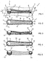
- the component of the invention is a pedal crank wholly indicated in figs. 1 and 2 with 1. It essentially consists of an elongated body 2 formed of a composite material 18, comprising small pieces of structural fibres incorporated in a matrix of polymeric material, the small pieces being arranged randomly, as it can be seen more clearly in fig. 2 .
- the pedal crank 1 has, at its end parts 3 and 4, respective seats 5 and 6 for mechanical coupling with the bottom bracket and with the pedal of the bicycle.
- the seats 5 and 6 incorporate cylindrical metal inserts 7 and 8 in which holes, not shown, are formed for connection to the bottom bracket and to the pedal, respectively.
- the seats 5 and 6 can consist of a hole of a suitable shape adapted to allow the direct connection of the pedal crank to the bottom bracket and to the pedal or else the subsequent insertion of metal inserts.
- middle plane ⁇ of the pedal crank 1 we mean a substantially flat surface which intersects the pedal crank 1 longitudinally and divides it substantially in half along its height H. Given the typical shape of the pedal crank 1, such a surface is slightly curved when one moves from one end 11 to the other 12 of the pedal crank 1.
- the continuous layers of structural fibres 13 and 14, which surround the end zones 9 and 10 of the seats 5 and 6, are realised in a single closed loop 15 of unidirectional fibres which extends longitudinally along the body 2 of the pedal crank 1.
- such a configuration could be different, like for example a series of unidirectional structural fibres surrounding the two seats 5 and 6 according to a typical "8-shaped" configuration.
- the continuous layers of 'structural fibres 13 and 14 are provided only in a part of the thicknesses S1 and S2 of the end zones 9 and 10 and can, at most, also be reduced to a single layer. Moreover, such layers 13 and 14 are provided only for a part of the height H of the pedal crank 1 and are confined in height by means of an annular retainer element 16, coaxial to the insert 7.
- the arrangement of a limited number of layers 13 and 14 of fibres in the pedal crank 1 implies that they are substantially covered with the composite material 18 with which the body 2 of the pedal crank 1 is made, as it can be seen more clearly in fig. 2 .
- the continuous layers of structural fibres can take different shapes and sizes.
- such layers can be made of interwoven structural fibres according to at least two incident directions to make a fabric.
- such a fabric comprises a majority of fibres orientated according to a direction parallel to the middle plane of the pedal crank 1.
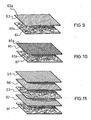
- the pedal crank 1, and specifically its elongated body 2 is formed with a semi-finished product, indicated with 60 in fig. 6 , consisting of three layers.
- One layer 61 formed of small pieces of structural fibre 61a incorporated in a matrix of polymeric material and arranged randomly inside the layer 61 and two layers 62 and 63 formed of continuous structural fibres 62a and 63a incorporated in a matrix of polymeric material and orientated according to directions which are complementary to each other, in particular -45° and +45°.
- the layers 61, 62 and 63 overlap one another and give the semi-finished product 60 characteristics of structural strength through the unidirectional fibres 62a and 63a and good characteristics of fluidity through the sheeted structure 61a, this last characteristic being exploited in the moulding step of the pedal crank 1.
- the arrangement and number of the layers, as well as the directions of the structural fibres, can be chosen according to the particular properties of structural strength of the component wished to be obtained.
- the layer 61 is arranged between the two layers 62 and 63.
- the embodiment of fig. 8 differs from that of fig. 6 in that the unidirectional fibres 72a and 73a incorporated in the matrix of polymeric material of the respective layers 72 and 73 define complementary directions respectively orientated at +90° and 0°.
- the semi-finished product has a layer of small pieces of structural fibres 61a incorporated in a matrix of polymeric material overlapping a single layer 63 formed of continuous structural fibres 63a orientated according to the +45° direction.
- the semi-finished product has a layer of small pieces of structural fibres 61a and a layer 81 in which the continuous structural fibres 81a are arranged according to two incident directions forming a fabric configuration.
- the semi-finished product 60 used for manufacturing the body 2 of the pedal crank 1, according to any of the illustrated embodiments and all other possible configurations, can also be rolled around a rolling axis before its use in the moulding step, as it shall be seen hereafter. This allows the characteristics of unidirectional strength of the structural fibres to be distributed in space.
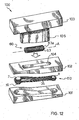
- the method provides for the use of a mould 100 formed by three parts, consisting of two half-shells 101 and 102 and a plunger 103.
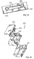
- the upper half-shell 102 as it can be seen more clearly in the bottom view thereof of fig. 13 , has a through-opening 104 which allows the passage and the sliding of a presser element 105 of the plunger 103.
- a first step of the method provides for the formation of the intermediate product 110 consisting of the inserts 7 and 8 on which the continuous layers of unidirectional structural fibres are wound in a closed loop configuration 35.
- Such an intermediate product 110 can be realised, for example, by winding a long fibre around the inserts 7, 8 with a number of layers sufficient to obtain the desired thickness and height.
- the arrangement of the fibres around the insert 7 is defined through the retainer element 16 which confines them in an upper portion of the insert 7.
- the intermediate product 110 thus obtained is placed inside the lower half-shell 101 above which the upper half-shell 102 is closed so that its shapings 102a and 102b are in contact with the heads of the metal inserts 7 and 8.
- the semi-finished product 60 previously wound around the rolling axis A is inserted in the through opening 104.
- the winding of the semi-finished product 60 is realised so that its outer surface consists of the layer 63 formed of unidirectional fibres 63a.
- the semi-finished product 60 is pre-heated to ease the subsequent moulding.
- the wound semi-finished product 60 is then in the zone defined between the inserts 7 and 8 and the inner part of the loop 35.
- the plunger 103 is lowered and the presser 105 slides inside the opening 104 of the upper half-shell 102 determining a thrusting action of the semi-finished product 60 inside the mould 100.
- the semi-finished product 60 uniformly fills the recess defined by the two half-shells 101 and 102, thanks to its fluidity.
- the closed loop configuration 35 of the unidirectional fibres allows them to keep their continuous configuration even during moulding, since the pressure forces applied by the composite material which constitutes the semi-finished product 60 are uniformly distributed along the loop 35.
- the mould 100 is heated, according to known techniques, and the material inside of it polymerises thus realising the desired pedal crank structure. Finally, the mould 100 is opened and the pedal crank is removed.
- any of the semi-finished products described above can be used, possibly even in non-wound configuration. If one wishes to manufacture the pedal crank according to the shape shown in fig. 5 , it is then advisable for the intermediate product, in this case consisting of the inserts on which the unidirectional fibres are individually wound, to undergo a prepolymerisation treatment, so that the subsequent moulding does not modify the shape of the wound fibres.
- a variant of the mould shown in fig. 12 is shown which is used for manufacturing a branched pedal crank, commonly known as right pedal crank.
- a method differs from the previous one in that the semi-finished product, when inserted in the mould 200, covers the top of the metal insert intended for coupling with the bottom bracket. In this case, the access to such a metal insert can take place by the subsequent removal of material through machining. Or else, instead of the metal insert a support can be used for the winding of the unidirectional fibres which remains incorporated in the pedal crank and then a seat can be formed, through machining, for direct coupling with the bottom bracket or the insertion of a metal insert. It is also clear that the mould 200 can be modified so as to obtain a right pedal crank in which also the insert intended for coupling with the bottom bracket is immediately accessible.
- Figs. 15 and 16 show the progression of the continuous layers of structural fibres 413a, 413b, 413c, 413d for manufacturing a branched pedal crank, commonly referred to as a right pedal crank.
- the continuous layers of structural fibres 413a, 413b, 413c, 413d partially surround the seats 405a, 405b, 405c, 405d of the end parts 403a, 403b, 403c, 403d of the spokes for an arc of circumference of about 180°.
- Such layers are each arranged in such a way as to form respective loops 415a, 415b, 415c, 415d which close on the central zone 414 where the pedal crank has a suitable seat 406 for the connection to the bottom bracket.
- the structural fibres thus arranged define an intermediate product 400 which is star-shaped. As shown in fig. 15 , such an intermediate product 400 is advantageously made through continuous winding, along suitable paths, of continuous layers of unidirectional fibre.
- the intermediate product 400 can be made directly inside the mould, for example inside the mould shown in fig. 14 , or else it can be made separately using a mask which mirrors the shape of the spokes.
- the manufacturing of the intermediate product 400 separately allows a prior preheating of the fibres to be realised and allows them to be given a pre-shaping before the positioning in loco into the mould.
- the intermediate product 400 is arranged inside the mould 200 on a plane overlapping the one in which the closed loop of structural fibres 15 (represented in fig. 2 ) is arranged, said fibres being arranged along the elongated body 2 of the pedal crank.'
- the configuration thus obtained allows a right pedal crank to be manufactured having simultaneously the zones intended for coupling with the pedal and with the bottom bracket and the ends of the spokes with high structural and mechanical continuity.
- each seat 405a, 405b, 405c, 405d can be completely surrounded by structural fibres 413a, 413b, 413c, 413d by using a closed loop configuration of the type shown in fig. 5 .
- the same result can be obtained through the manufacturing of a pre-formed semi-finished product 500, as shown in figure 18 , where the continuous layers of structural fibres associated with the spokes and with the main body are on the same plane and substantially constitute a single element according to a comet-shape.
- the intermediate product 500 can be manufactured directly inside the mould or else can be manufactured separately using a mask which mirrors the shape of the pedal crank.
Landscapes
- Engineering & Computer Science (AREA)
- Mechanical Engineering (AREA)
- Chemical & Material Sciences (AREA)
- Composite Materials (AREA)
- Textile Engineering (AREA)
- Combustion & Propulsion (AREA)
- Transportation (AREA)
- Moulding By Coating Moulds (AREA)
- Ropes Or Cables (AREA)
- Laminated Bodies (AREA)
- Shafts, Cranks, Connecting Bars, And Related Bearings (AREA)
Claims (15)
- Procédé de fabrication d'un composant de bicyclette (1; 20) comprenant un corps allongé (2) constitué de fibres structurelles incorporées dans une matrice de matériau polymère (18, 38) et comportant, à une partie d'extrémité de celui-ci (3, 4 ; 403a, 403b, 403c, 403d), un siège (5, 6 ; 45, 46 ; 405a, 405b, 405c, 405d, 406) destiné à un accouplement mécanique avec un élément de la bicyclette, où le procédé comprend les étapes suivantes :- l'agencement, au niveau d'une première moitié (101 ; 201) d'un moule (100; 200), d'une couche continue de fibres dans une configuration de façon à entourer au moins partiellement ledit siège (5, 6 ; 45, 46 ; 405a, 405b, 405c, 405d, 406) ;- la fermeture d'une deuxième moitié (102 ; 202) du moule (100 ; 200) au-dessus de ladite première moitié (101 ; 201),- l'insertion, à partir d'une ouverture (104 ; 204) dans ladite deuxième moitié (102 ; 202) du moule (100 ; 200), d'un matériau composite (18 ; 38) comprenant de petites parties de fibres structurelles incorporées dans une matrice d'un matériau polymère et agencées de façon aléatoire à l'intérieur de la matrice,- l'insertion, dans ladite ouverture (104 ; 204) au niveau de ladite moitié (102 ; 202) du moule (100 ; 200), d'un poinçon (103) et la soumission dudit matériau composite à une pression pour permettre à l'évidement défini par le moule d'être rempli,- l'augmentation de la température du moule (100 ; 200) jusqu'à une valeur qui permet la réticulation du matériau polymère de ladite matrice,- la séparation des deux parties (101, 102 ; 201, 202) du moule (100 ; 200) et le retrait dudit composant (1 ; 20).
- Procédé selon la revendication 1, caractérisé en ce qu'il comprend une autre étape de formation dudit matériau composite par chevauchement au moins d'une première couche (62, 63 ; 72, 73 ; 81 ; 92, 94, 95) formée de fibres structurelles continues (62a, 63a; 72a, 73a; 81a) incorporées dans une matrice du matériau polymère et au moins d'une deuxième couche (61 ; 91, 93) fournée de petites parties de fibres structurelles (61a) incorporées dans une matrice du matériau polymère et disposées de façon aléatoire à l'intérieur de la couche,
- Procédé selon la revendication 2, caractérisé en ce qu'il comprend une autre étape de laminage desdites couches (61, 62, 63 ; 61, 72, 73 ; 61, 81 ; 91, 92, 93, 94, 95) avant leur insertion à l'intérieur du moule.
- Procédé selon la revendication 3, caractérisé en ce que ladite étape de laminage est réalisée de telle sorte que ladite première couche se situe sur l'extérieur.
- Procédé selon la revendication 1, caractérisé en ce que la disposition de ladite couche continue de fibres à l'intérieur de la première moitié (101 ; 200) du moule (100 ; 200) est réalisée par l'enroulage desdites fibres autour de deux pièces rapportées.
- Procédé selon la revendication 5, caractérisé en ce que ledit enroulage réalise une seule boucle (15 ; 35) autour desdites pièces rapportées.
- Procédé selon la revendication 5, caractérisé en ce que ledit enroulage réalise une boucle respective (53, 54) pour chaque pièce apportée.
- Procédé selon la revendication 4, caractérisé en ce qu'une polymérisation préventive desdites fibres avant leur insertion à l'intérieur du moule (100 ; 200) est effectuée.
- Procédé selon la revendication 2, caractérisé en ce que lesdites fibres structurelles continues (62a, 63a ; 72a, 73a) de ladite première couche (62, 63 ; 72, 73 ; 92, 94, 95) sont des fibres unidirectionnelles.
- Procédé selon la revendication 2, caractérisé en ce que lesdites fibres structurelles continues (81a) sont disposées dans ladite première couche (81) selon deux ou plusieurs directions incidentes afin de former une configuration de tissu.
- Procédé selon la revendication 2, caractérisé en ce que ladite étape de formation dudit matériau composite comprend en outre le chevauchement d'une troisième couche (63, 62 ; 73, 72) de fibres structurelles continues (63a, 62a ; 73a, 72a) formées de fibres unidirectionnelles disposées selon une direction complémentaire à la direction desdites fibres unidirectionnelles (62a, 63a ; 72a, 73a) de ladite première couche (62, 63 ; 72, 73).
- Procédé selon la revendication 11, caractérisé en ce que lesdites directions desdites fibres unidirectionnelles (62a, 63a) desdites première et troisième couches (62, 63) sont + 45° et - 45° respectivement.
- Procédé selon la revendication 11, caractérisé en ce que lesdites première, deuxième et troisième couches (62, 61, 63) sont agencées les unes à côté des autres où ladite deuxième couche (61) ne se situe pas entre les deux autres (62, 63).
- Procédé selon la revendication 11, caractérisé en ce que lesdites première, deuxième et troisième couches (61, 62, 63 ; 61, 72, 73 ; 61, 81 ; 91, 92, 93, 94, 95) de fibres structurelles sont laminées le long d'un axe de laminage (A) de sorte que dans une configuration laminée, ladite première ou deuxième couche (62, 63 ; 72, 73 ; 81 ; 92, 94, 95) se situe sur l'extérieur.
- Procédé selon la revendication 2, caractérisé en ce que ladite étape de formation dudit matériau composite comprend le chevauchement d'un nombre quelconque des couches, selon les revendications 9 à 12.
Priority Applications (11)
| Application Number | Priority Date | Filing Date | Title |
|---|---|---|---|
| EP20030425530 EP1486413B1 (fr) | 2003-06-11 | 2003-08-01 | Procédé de fabrication d'un composant de bicyclette |
| EP20090009915 EP2130756B1 (fr) | 2003-06-11 | 2003-08-01 | Composant de bicyclette et procédé de fabrication d'un tel composant |
| EP20090009916 EP2110302A1 (fr) | 2003-06-11 | 2003-08-01 | Composant de bicyclette |
| TW93116194A TWI326661B (en) | 2003-06-11 | 2004-06-04 | Bicycle component and method for manufacturing such a component |
| US10/861,206 US8024993B2 (en) | 2003-06-11 | 2004-06-04 | Bicycle component and method for manufacturing such a component |
| TW98146465A TWI391288B (zh) | 2003-06-11 | 2004-06-04 | 腳踏車組件及其製備方法 |
| JP2004173152A JP4836413B2 (ja) | 2003-06-11 | 2004-06-10 | 自転車構成部品およびその製造方法 |
| CN2009101322073A CN101565080B (zh) | 2003-06-11 | 2004-06-11 | 自行车构件和用于制造该构件的方法 |
| CN2004100493679A CN1572650B (zh) | 2003-06-11 | 2004-06-11 | 自行车构件和用于制造该构件的方法 |
| US11/860,220 US20080054715A1 (en) | 2001-02-13 | 2007-09-24 | Bicycle wheel hub |
| US13/245,351 US10105916B2 (en) | 2003-06-11 | 2011-09-26 | Bicycle component and method for manufacturing such a component |
Applications Claiming Priority (3)
| Application Number | Priority Date | Filing Date | Title |
|---|---|---|---|
| EP03425378 | 2003-06-11 | ||
| EP03425378 | 2003-06-11 | ||
| EP20030425530 EP1486413B1 (fr) | 2003-06-11 | 2003-08-01 | Procédé de fabrication d'un composant de bicyclette |
Related Child Applications (4)
| Application Number | Title | Priority Date | Filing Date |
|---|---|---|---|
| EP20090009916 Division EP2110302A1 (fr) | 2003-06-11 | 2003-08-01 | Composant de bicyclette |
| EP20090009915 Division EP2130756B1 (fr) | 2003-06-11 | 2003-08-01 | Composant de bicyclette et procédé de fabrication d'un tel composant |
| EP09009915.1 Division-Into | 2009-07-31 | ||
| EP09009916.9 Division-Into | 2009-07-31 |
Publications (3)
| Publication Number | Publication Date |
|---|---|
| EP1486413A2 EP1486413A2 (fr) | 2004-12-15 |
| EP1486413A3 EP1486413A3 (fr) | 2004-12-29 |
| EP1486413B1 true EP1486413B1 (fr) | 2010-04-28 |
Family
ID=33300992
Family Applications (3)
| Application Number | Title | Priority Date | Filing Date |
|---|---|---|---|
| EP20090009915 Expired - Lifetime EP2130756B1 (fr) | 2003-06-11 | 2003-08-01 | Composant de bicyclette et procédé de fabrication d'un tel composant |
| EP20030425530 Expired - Lifetime EP1486413B1 (fr) | 2001-02-13 | 2003-08-01 | Procédé de fabrication d'un composant de bicyclette |
| EP20090009916 Ceased EP2110302A1 (fr) | 2003-06-11 | 2003-08-01 | Composant de bicyclette |
Family Applications Before (1)
| Application Number | Title | Priority Date | Filing Date |
|---|---|---|---|
| EP20090009915 Expired - Lifetime EP2130756B1 (fr) | 2003-06-11 | 2003-08-01 | Composant de bicyclette et procédé de fabrication d'un tel composant |
Family Applications After (1)
| Application Number | Title | Priority Date | Filing Date |
|---|---|---|---|
| EP20090009916 Ceased EP2110302A1 (fr) | 2003-06-11 | 2003-08-01 | Composant de bicyclette |
Country Status (5)
| Country | Link |
|---|---|
| US (2) | US8024993B2 (fr) |
| EP (3) | EP2130756B1 (fr) |
| JP (1) | JP4836413B2 (fr) |
| CN (1) | CN1572650B (fr) |
| TW (2) | TWI391288B (fr) |
Cited By (5)
| Publication number | Priority date | Publication date | Assignee | Title |
|---|---|---|---|---|
| US11142280B2 (en) | 2016-03-24 | 2021-10-12 | The Hive Global, Inc. | Bicycle crank with spindle attachment structure |
| US11351815B2 (en) | 2017-08-21 | 2022-06-07 | The Hive Global, Inc. | Bicycle cassette with clamping connection |
| US11485449B2 (en) | 2015-09-01 | 2022-11-01 | The Hive Global, Inc. | Bicycle cassette with locking connection |
| US11932351B2 (en) | 2020-07-17 | 2024-03-19 | The Hive Global, Inc. | Conical bicycle cassette sprocket structure |
| US12030586B2 (en) | 2021-07-12 | 2024-07-09 | The Hive Global, Inc. | Seal for bicycle crank with differential chainring motion |
Families Citing this family (51)
| Publication number | Priority date | Publication date | Assignee | Title |
|---|---|---|---|---|
| EP1486412B1 (fr) | 2003-06-10 | 2014-05-07 | Campagnolo S.R.L. | Pédalier de bicyclette |
| EP2130756B1 (fr) | 2003-06-11 | 2012-10-03 | CAMPAGNOLO S.r.l. | Composant de bicyclette et procédé de fabrication d'un tel composant |
| US20060012650A1 (en) * | 2004-04-12 | 2006-01-19 | Seiko Epson Corporation | Liquid-supplying member, liquid-injection apparatus, mounting method, fluid-carrying tube, and manufacturing method of fluid-carrying tube |
| EP1749736A1 (fr) | 2005-08-03 | 2007-02-07 | Campagnolo S.R.L. | Partie de bicyclette de matériau composite avec inserts et manufacture |
| EP1818251A1 (fr) * | 2006-02-14 | 2007-08-15 | CAMPAGNOLO S.r.l. | Pédalier de bicyclette, produit intermédiaire et méthode pour fabriquer un tel pédalier |
| ATE523419T1 (de) | 2006-02-14 | 2011-09-15 | Campagnolo Srl | Fahrradtretkurbel und herstellungsmethode für eine derartige tretkurbel |
| DE102006058377B4 (de) * | 2006-12-08 | 2010-09-16 | Airbus Deutschland Gmbh | Stange zur strukturellen Verstärkung einer Rumpfstruktur eines Flugzeugs |
| DE102008033621A1 (de) * | 2008-07-17 | 2010-01-21 | Volkswagen Ag | Kunststoffbauteil für Fahrzeuge, insbesondere Kraftfahrzeuge, und Verfahren zur Herstellung desselben |
| WO2012115599A2 (fr) * | 2011-02-18 | 2012-08-30 | Mustafa Celik | Procédé de fabrication d'éléments précontraints et obtention d'éléments structuraux supérieurs et inférieurs en composite ultra-résistant |
| ES2692653T3 (es) | 2012-08-21 | 2018-12-04 | Avery Dennison Corporation | Sistemas y métodos para fabricar películas, fibras, esferas y otros artículos porosos |
| ITMI20122229A1 (it) * | 2012-12-21 | 2014-06-22 | Campagnolo Srl | Componente di bicicletta comprendente un corpo in alluminio ed un corpo in materiale composito, e metodo di fabbricazione di tale componente |
| JP2014133446A (ja) * | 2013-01-09 | 2014-07-24 | Nippon Light Metal Co Ltd | 車両用高強度サスペンション部品およびその製造方法 |
| DE102014217215A1 (de) * | 2013-09-17 | 2015-03-19 | F&G Engineering Gmbh | Verfahren zum Wickeln von Faserverbundbauteilen |
| DE102014103701B3 (de) | 2014-03-18 | 2015-05-21 | Holger Faupel | Kurbelarm für ein Fahrrad-Tretkurbelsystem und Herstellungsverfahren dafür |
| US9504550B2 (en) | 2014-06-26 | 2016-11-29 | Vertera, Inc. | Porous devices and processes for producing same |
| US9498922B2 (en) | 2014-06-26 | 2016-11-22 | Vertera, Inc. | Apparatus and process for producing porous devices |
| US10184510B2 (en) * | 2015-05-09 | 2019-01-22 | James Walter Linck | Method of making a carbon composite piston engine crankshaft |
| USD815281S1 (en) | 2015-06-23 | 2018-04-10 | Vertera, Inc. | Cervical interbody fusion device |
| FR3044119B1 (fr) * | 2015-11-19 | 2017-12-29 | Carbody | Procede de fabrication en materiau composite, d'un dispositif de pedale pour un vehicule |
| GB201611862D0 (en) * | 2016-07-07 | 2016-08-24 | Williams Grand Prix Eng Ltd | A structural member |
| US11091217B2 (en) * | 2017-01-26 | 2021-08-17 | Giant Manufacturing Co., Ltd. | Joint structure of a composite bicycle frame and manufacturing method thereof |
| JP6708582B2 (ja) * | 2017-04-10 | 2020-06-10 | トヨタ自動車株式会社 | 車両のサスペンションアーム |
| FR3067279B1 (fr) * | 2017-06-13 | 2021-02-19 | Conseil & Technique | Procede de realisation d'une piece en materiau composite, et piece composite obtenue |
| DE102017113421A1 (de) * | 2017-06-19 | 2018-12-20 | Thyssenkrupp Ag | Verfahren zum Herstellen eines Faserverbundbauteils |
| CN107415572A (zh) * | 2017-06-19 | 2017-12-01 | 厦门连科工业有限公司 | 一种新型辐条结构及其装配方法 |
| DE102017213564A1 (de) * | 2017-08-04 | 2019-02-07 | Zf Friedrichshafen Ag | Dreipunktlenker und Herstellungsverfahren für einen Dreipunktlenker |
| DE102017128691B4 (de) * | 2017-12-04 | 2025-03-06 | Dr. Ing. H.C. F. Porsche Aktiengesellschaft | Verbindungsstrebe |
| DE102017222579A1 (de) * | 2017-12-13 | 2019-06-13 | Schäfer MWN GmbH | Verfahren zum Herstellen eines Bauelements und Bauelement |
| FR3075408B1 (fr) * | 2017-12-15 | 2020-01-10 | Carbody | Dispositif de pedale de frein |
| IT201800005302A1 (it) | 2018-05-11 | 2019-11-11 | Pedivella di bicicletta dal lato trasmissione, dotata di rilevatore di sforzi/deformazioni per un misuratore di coppia o di potenza, nonche' metodi correlati | |
| IT201800005297A1 (it) | 2018-05-11 | 2019-11-11 | Pedivella di bicicletta e relativa guarnitura | |
| CA3042547A1 (fr) | 2018-05-11 | 2019-11-11 | Campagnolo S.R.L. | Manivelle de bicyclette comportant un systeme electrique/electronique |
| IT201800005294A1 (it) * | 2018-05-11 | 2019-11-11 | Componente di bicicletta in materiale composito e relativo processo di fabbricazione | |
| IT201800005299A1 (it) | 2018-05-11 | 2019-11-11 | Componente di bicicletta dotato di sensore di sforzi/deformazioni compensato in temperatura | |
| DE102018126998A1 (de) * | 2018-10-29 | 2020-04-30 | Boge Elastmetall Gmbh | Verfahren zur Herstellung eines Lenkers oder Lenkerkörpers aus endlosfaserverstärktem Kunststoff |
| DE102019206435A1 (de) * | 2019-05-06 | 2020-11-12 | Schäfer MWN GmbH | Mehrpunktlenker für ein Fahrwerk eines Fahrzeugs |
| DE102019206436A1 (de) * | 2019-05-06 | 2020-11-12 | Schäfer MWN GmbH | Mehrpunktlenker für ein Fahrwerk eines Fahrzeugs |
| US12117040B2 (en) | 2019-06-23 | 2024-10-15 | Albany Engineered Composites, Inc. | Rod end made of thermoplastic fiber-reinforced plastic |
| DE102019004341A1 (de) * | 2019-06-23 | 2020-12-24 | Albany Engineered Composites, Inc. | Stangenkopf aus thermoplastischem Faser-Kunststoff-Verbund (FKV) |
| GB2587209A (en) * | 2019-09-18 | 2021-03-24 | Lentus Composites Ltd | Composite material panels |
| IL295082A (en) * | 2020-03-13 | 2022-09-01 | Galactic Co Llc | Control cables and composite stabilizer cables for aircraft applications and methods of their manufacture |
| TWI741649B (zh) * | 2020-06-12 | 2021-10-01 | 世同金屬股份有限公司 | 複合曲柄及其製造方法 |
| CN113043527B (zh) * | 2021-02-09 | 2022-05-27 | 博戈橡胶塑料(株洲)有限公司 | 一种轻量化复合材料推力杆制作方法 |
| CN113021939B (zh) * | 2021-02-09 | 2022-04-22 | 博戈橡胶塑料(株洲)有限公司 | 基于连续纤维与普通纤维的轻量化部件制作方法及制品 |
| WO2022204158A1 (fr) | 2021-03-26 | 2022-09-29 | The Hive Global, Inc. | Tige de selle de bicyclette télescopique à hauteur réglable et insertion de cadre fixe |
| IT202100025118A1 (it) * | 2021-09-30 | 2023-03-30 | Piaggio & C Spa | Assieme per motocicletta, motocicletta e relativo metodo di fabbricazione dell’assieme |
| TWI901904B (zh) * | 2021-10-12 | 2025-10-21 | 美商速聯有限責任公司 | 自行車曲柄臂 |
| DE202022103016U1 (de) | 2022-05-29 | 2023-08-31 | Igus Gmbh | Tretkurbel, insbesondere Fahrradtretkurbel, mit Kurbelarmköper aus Kunststoff |
| CN115123438A (zh) * | 2022-06-27 | 2022-09-30 | 厦门市鑫和翔工贸有限公司 | 一种曲柄、曲柄的制造方法及曲柄注塑用模具 |
| DE102022129801A1 (de) | 2022-11-10 | 2024-05-16 | MIRANDA & IRMÃO, LDª | Kurbelarm und Kurbelarmanordnung für ein Fahrrad |
| IT202300019509A1 (it) * | 2023-09-22 | 2025-03-22 | Italica S R L | Procedimento e stampo per la produzione di oggetti in materiale composito |
Citations (1)
| Publication number | Priority date | Publication date | Assignee | Title |
|---|---|---|---|---|
| FR2636386A1 (fr) * | 1988-09-13 | 1990-03-16 | Peyrard | Piece allongee a resistance mecanique elevee, et son procede de fabrication |
Family Cites Families (65)
| Publication number | Priority date | Publication date | Assignee | Title |
|---|---|---|---|---|
| US3080893A (en) * | 1956-06-29 | 1963-03-12 | Minnesota Mining & Mfg | Reinforced rigid plastic pipe |
| GB1574825A (en) | 1976-03-31 | 1980-09-10 | Rubery Owen Fasteners Ltd | Screw threaded members and their manufacture |
| FR2416829A1 (fr) | 1978-02-10 | 1979-09-07 | Gauthier Robert | Manivelle allegee et rigide a longueur variable |
| JPS5642533A (en) | 1979-09-12 | 1981-04-20 | Mitsubishi Rayon Co | Fishing reel and production thereof |
| DE2951111C2 (de) | 1979-12-19 | 1983-10-13 | Messerschmitt-Bölkow-Blohm GmbH, 8000 München | Pleuelstange für Kraftmaschinen |
| JPS57111694A (en) | 1980-12-27 | 1982-07-12 | Omron Tateisi Electronics Co | Device for treating card |
| FR2546473B1 (fr) * | 1983-05-24 | 1987-12-11 | Verre Tisse Sa | Materiau tubulaire a base d'une resine renforcee par une matiere textile et cadre de bicyclette ou vehicule similaire realise a partir d'un tel materiau |
| JPS6022323A (ja) | 1983-07-18 | 1985-02-04 | Rohm Co Ltd | 絶縁層ドライエツチの終点検出方法 |
| JPS60234762A (ja) * | 1984-05-03 | 1985-11-21 | Toyoda Autom Loom Works Ltd | 強化繊維成形体の製造方法とその装置 |
| JPS6166636A (ja) | 1984-09-11 | 1986-04-05 | Mitsubishi Heavy Ind Ltd | 繊維強化プラスチツク成形品及びその製造方法 |
| JPS61135801A (ja) | 1984-12-06 | 1986-06-23 | Toray Ind Inc | 車輪 |
| JPS61137634A (ja) | 1984-12-07 | 1986-06-25 | Sugino Techno:Kk | 自転車用クランクの製造方法 |
| JPH0674072B2 (ja) * | 1986-05-12 | 1994-09-21 | ジェイ トリンブル,ブレント | 複合自転車フレームおよびその製造方法 |
| DE3763809D1 (de) | 1986-10-31 | 1990-08-23 | Look Sa | Kurbel fuer tretlager eines fahrrads. |
| FR2612549B1 (fr) * | 1987-03-20 | 1989-06-30 | Cahors App Elec | Armement isolant pour poteau de support de lignes electriques et son procede de fabrication |
| US4900048A (en) * | 1987-10-02 | 1990-02-13 | Gleb Derujinsky | Integral seamless composite bicycle frame |
| US4856801A (en) | 1987-12-16 | 1989-08-15 | Cycle Composites, Inc. | Integral rear wheel suspension for composite material bicycle frame |
| JPH04339635A (ja) | 1991-02-08 | 1992-11-26 | Sekisui Chem Co Ltd | 繊維強化合成樹脂複合体及びその成形方法 |
| JP2567828B2 (ja) * | 1991-04-03 | 1996-12-25 | 日東紡績株式会社 | 成形用シート材料及び安全靴先芯 |
| JPH04347006A (ja) | 1991-05-24 | 1992-12-02 | Sumitomo Metal Ind Ltd | 繊維強化プラスチック製駆動軸 |
| US5215322A (en) | 1991-12-10 | 1993-06-01 | Enders Mark L | Dual and single seat composite bicycle frames and fabrication methods therefore |
| US5624519A (en) * | 1992-05-29 | 1997-04-29 | Trek Bicycle, Corp. | Method making a composite bicycle frame using composite lugs |
| US5271784A (en) * | 1992-12-18 | 1993-12-21 | Industrial Technology Research Institute | Method for manufacturing composite bicycle frames |
| JPH06321167A (ja) | 1993-05-14 | 1994-11-22 | Mitsubishi Rayon Co Ltd | 自転車用クランク |
| US5435869A (en) * | 1993-08-27 | 1995-07-25 | Christensen; Roland | Method for manufacturing a composite crank arm |
| US5632940A (en) * | 1994-03-29 | 1997-05-27 | Whatley; Bradford L. | Method of making an integrally stiffened article |
| FR2722753B1 (fr) * | 1994-07-25 | 1996-10-11 | Corima | 1tige de selle pour cadre de cycle |
| DE29600548U1 (de) | 1996-01-13 | 1996-02-29 | Alfred Thun & Co GmbH, 58256 Ennepetal | Tretkurbel für ein Fahrrad |
| DE19601125C2 (de) | 1996-01-13 | 1999-01-28 | Thun Alfred & Co Gmbh | Tretkurbel für ein Fahrrad |
| CN2278644Y (zh) | 1996-10-11 | 1998-04-15 | 王志宏 | 自行车曲柄结构 |
| US5904072A (en) | 1996-12-20 | 1999-05-18 | Shimano Inc. | Bicycle crank arm |
| CN1062647C (zh) | 1997-01-02 | 2001-02-28 | 林玉琴 | 曲柄的制造方法 |
| US5851459A (en) * | 1997-03-31 | 1998-12-22 | Chen; Jason | Method for manufacturing cranks for bicycles |
| US6443033B1 (en) | 1997-04-11 | 2002-09-03 | Timothy Eugene Brummer | Two-piece bicycle crankset |
| US5941135A (en) | 1997-06-18 | 1999-08-24 | Schlanger; Raphael | Bicycle crankshaft assembly |
| US6324940B1 (en) * | 1997-08-13 | 2001-12-04 | Maclean-Fogg Company | Composite link |
| FR2770802B1 (fr) * | 1997-11-13 | 2000-02-11 | Duqueine | Procede de moulage d'une piece composite, structure composite employee dans ce procede et manivelle obtenue selon ce procede |
| JPH11166552A (ja) | 1997-12-08 | 1999-06-22 | Toho Rayon Co Ltd | Frp製シャフトと継手との接合構造および接合方法 |
| US6265333B1 (en) * | 1998-06-02 | 2001-07-24 | Board Of Regents, University Of Nebraska-Lincoln | Delamination resistant composites prepared by small diameter fiber reinforcement at ply interfaces |
| US6268047B1 (en) * | 1999-01-22 | 2001-07-31 | Ppg Industries Ohio, Inc. | Glass fiber mats, laminates reinforced with the same and methods for making the same |
| US7070376B1 (en) | 1999-12-14 | 2006-07-04 | Simpson Strong-Tie Company, Inc. | Self-drilling, self-anchoring fastener for concrete |
| US6305243B1 (en) * | 2000-02-04 | 2001-10-23 | Douglas Chiang | Bicycle crank arm |
| CN2425848Y (zh) * | 2000-05-12 | 2001-04-04 | 林珍妮 | 自行车曲柄 |
| TW461866B (en) * | 2000-06-12 | 2001-11-01 | Advanced Int Multitech Co Ltd | Manufacture method of polymeric composite bicycle hollow crank |
| JP2003072666A (ja) * | 2001-06-27 | 2003-03-12 | Campagnolo Spa | 自転車用クランク、及び当該クランクの製造方法 |
| ITTO20010617A1 (it) * | 2001-06-27 | 2002-12-27 | Campagnolo Srl | Pedivella per bicicletta e procedimento per la sua fabbricazione. |
| ITTO20010621A1 (it) * | 2001-06-27 | 2002-12-27 | Campagnolo Srl | Pedivella per bicicletta e procedimento per la sua fabbricazione. |
| ITTO20010782A1 (it) * | 2001-08-03 | 2003-02-03 | Campagnolo Srl | Procedimento per la produzione di una pedivella per bicicletta. |
| CN2509074Y (zh) | 2001-08-13 | 2002-09-04 | 明安国际企业股份有限公司 | 高分子复合材料的自行车空心曲柄 |
| US20030061900A1 (en) | 2001-09-28 | 2003-04-03 | Smith Garrett Andrew | Bicycle crank pedal insert |
| US8071491B2 (en) * | 2001-11-07 | 2011-12-06 | FledForm Technologies, LLC | Process, composition and coating of laminate material |
| EP1350714A1 (fr) | 2002-03-19 | 2003-10-08 | Campagnolo Srl | Bras de manivelle d'une bicyclette et procédé de fabrication |
| US6924021B1 (en) * | 2002-07-03 | 2005-08-02 | Trek Bicycle Corporation | Complex-shaped carbon fiber structural member and its method of manufacture |
| US6564675B1 (en) * | 2002-07-23 | 2003-05-20 | Cheng-Xun Jiang | Crank arm for bicycles |
| EP1419961A1 (fr) | 2002-11-15 | 2004-05-19 | IPA N.V.-Composites | Pédalier creux pour bicyclette |
| US7503239B2 (en) | 2003-01-30 | 2009-03-17 | Shimano Inc. | Bicycle crank arm assembly |
| US20040177717A1 (en) | 2003-03-13 | 2004-09-16 | Cheng-Hsun Chiang | Bicycle crank |
| EP1486412B1 (fr) | 2003-06-10 | 2014-05-07 | Campagnolo S.R.L. | Pédalier de bicyclette |
| EP2130756B1 (fr) | 2003-06-11 | 2012-10-03 | CAMPAGNOLO S.r.l. | Composant de bicyclette et procédé de fabrication d'un tel composant |
| EP1506882B1 (fr) * | 2003-08-11 | 2008-07-09 | Campagnolo Srl | Jante composite de bicyclette et procédé de sa fabrication |
| US7309668B2 (en) * | 2003-12-03 | 2007-12-18 | Elk Premium Building Products, Inc. | Multiple layer directionally oriented nonwoven fiber material and methods of manufacturing same |
| JP2006007799A (ja) | 2004-06-22 | 2006-01-12 | Shimano Inc | 自転車用スプロケット |
| ATE523419T1 (de) | 2006-02-14 | 2011-09-15 | Campagnolo Srl | Fahrradtretkurbel und herstellungsmethode für eine derartige tretkurbel |
| EP1818251A1 (fr) | 2006-02-14 | 2007-08-15 | CAMPAGNOLO S.r.l. | Pédalier de bicyclette, produit intermédiaire et méthode pour fabriquer un tel pédalier |
| EP1840022B1 (fr) | 2006-03-29 | 2010-03-03 | CAMPAGNOLO S.r.l. | Assemblage de manivelle de bicyclette et les éléments liés |
-
2003
- 2003-08-01 EP EP20090009915 patent/EP2130756B1/fr not_active Expired - Lifetime
- 2003-08-01 EP EP20030425530 patent/EP1486413B1/fr not_active Expired - Lifetime
- 2003-08-01 EP EP20090009916 patent/EP2110302A1/fr not_active Ceased
-
2004
- 2004-06-04 TW TW98146465A patent/TWI391288B/zh not_active IP Right Cessation
- 2004-06-04 TW TW93116194A patent/TWI326661B/zh not_active IP Right Cessation
- 2004-06-04 US US10/861,206 patent/US8024993B2/en not_active Expired - Fee Related
- 2004-06-10 JP JP2004173152A patent/JP4836413B2/ja not_active Expired - Fee Related
- 2004-06-11 CN CN2004100493679A patent/CN1572650B/zh not_active Expired - Fee Related
-
2011
- 2011-09-26 US US13/245,351 patent/US10105916B2/en not_active Expired - Fee Related
Patent Citations (1)
| Publication number | Priority date | Publication date | Assignee | Title |
|---|---|---|---|---|
| FR2636386A1 (fr) * | 1988-09-13 | 1990-03-16 | Peyrard | Piece allongee a resistance mecanique elevee, et son procede de fabrication |
Cited By (5)
| Publication number | Priority date | Publication date | Assignee | Title |
|---|---|---|---|---|
| US11485449B2 (en) | 2015-09-01 | 2022-11-01 | The Hive Global, Inc. | Bicycle cassette with locking connection |
| US11142280B2 (en) | 2016-03-24 | 2021-10-12 | The Hive Global, Inc. | Bicycle crank with spindle attachment structure |
| US11351815B2 (en) | 2017-08-21 | 2022-06-07 | The Hive Global, Inc. | Bicycle cassette with clamping connection |
| US11932351B2 (en) | 2020-07-17 | 2024-03-19 | The Hive Global, Inc. | Conical bicycle cassette sprocket structure |
| US12030586B2 (en) | 2021-07-12 | 2024-07-09 | The Hive Global, Inc. | Seal for bicycle crank with differential chainring motion |
Also Published As
| Publication number | Publication date |
|---|---|
| EP1486413A2 (fr) | 2004-12-15 |
| TWI391288B (zh) | 2013-04-01 |
| CN1572650A (zh) | 2005-02-02 |
| TWI326661B (en) | 2010-07-01 |
| US8024993B2 (en) | 2011-09-27 |
| TW200502130A (en) | 2005-01-16 |
| TW201016540A (en) | 2010-05-01 |
| US10105916B2 (en) | 2018-10-23 |
| EP2110302A1 (fr) | 2009-10-21 |
| EP2130756B1 (fr) | 2012-10-03 |
| CN1572650B (zh) | 2010-04-28 |
| JP4836413B2 (ja) | 2011-12-14 |
| JP2005001662A (ja) | 2005-01-06 |
| EP2130756A1 (fr) | 2009-12-09 |
| US20050012298A1 (en) | 2005-01-20 |
| US20120064284A1 (en) | 2012-03-15 |
| EP1486413A3 (fr) | 2004-12-29 |
Similar Documents
| Publication | Publication Date | Title |
|---|---|---|
| EP1486413B1 (fr) | Procédé de fabrication d'un composant de bicyclette | |
| US4828285A (en) | Bicycle fork or similar article based on a resin reinforced by a textile structure and process for manufacturing same | |
| EP1281609B1 (fr) | Procédé de production d'un levier de manivelle pour une bicyclette et levier de manivelle pour une bicyclette | |
| US7000499B2 (en) | Bicycle crank and method for manufacturing said crank | |
| TWI389817B (zh) | 自行車之曲柄臂,及用於製造該曲柄臂的中間產物及方法 | |
| US7013753B2 (en) | Bicycle crank and method for manufacturing said crank | |
| WO1990010570A1 (fr) | Cadre de bicyclette en materiau sans talons et son procede de fabrication | |
| JP2007223586A (ja) | 自転車のクランク・アーム、その中間製品および該クランク・アームの製造方法 | |
| KR20170140335A (ko) | 예를 들면 차륜 서스펜션용 링크 암 및 그 제조 방법 | |
| JP2011522723A (ja) | 有機マトリックス複合材から作られる構造部品を製造する方法、および得られる部品 | |
| US5928736A (en) | Composite structure having integrated aperture and method for its preparation | |
| EP0134617B1 (fr) | Ressort en matière renforcée de fibres pour véhicule automobile | |
| JP2009052612A (ja) | 繊維強化樹脂製歯車 | |
| US20190351627A1 (en) | Method for manufacturing multilayer fiber reinforced resin composite and molded product using the same | |
| CN101565080B (zh) | 自行车构件和用于制造该构件的方法 | |
| JPH07562A (ja) | ラケットフレーム及びその製造方法 | |
| KR102391001B1 (ko) | 복합재 코일 스프링 및 그 제조방법 |
Legal Events
| Date | Code | Title | Description |
|---|---|---|---|
| PUAI | Public reference made under article 153(3) epc to a published international application that has entered the european phase |
Free format text: ORIGINAL CODE: 0009012 |
|
| PUAL | Search report despatched |
Free format text: ORIGINAL CODE: 0009013 |
|
| AK | Designated contracting states |
Kind code of ref document: A2 Designated state(s): AT BE BG CH CY CZ DE DK EE ES FI FR GB GR HU IE IT LI LU MC NL PT RO SE SI SK TR |
|
| AX | Request for extension of the european patent |
Extension state: AL LT LV MK |
|
| AK | Designated contracting states |
Kind code of ref document: A3 Designated state(s): AT BE BG CH CY CZ DE DK EE ES FI FR GB GR HU IE IT LI LU MC NL PT RO SE SI SK TR |
|
| AX | Request for extension of the european patent |
Extension state: AL LT LV MK |
|
| 17P | Request for examination filed |
Effective date: 20050616 |
|
| AKX | Designation fees paid |
Designated state(s): AT BE BG CH CY CZ DE DK EE ES FI FR GB GR HU IE IT LI LU MC NL PT RO SE SI SK TR |
|
| 17Q | First examination report despatched |
Effective date: 20051201 |
|
| 17Q | First examination report despatched |
Effective date: 20051201 |
|
| RTI1 | Title (correction) |
Free format text: METHOD FOR MANUFACTURING A BICYCLE COMPONENT |
|
| GRAP | Despatch of communication of intention to grant a patent |
Free format text: ORIGINAL CODE: EPIDOSNIGR1 |
|
| GRAS | Grant fee paid |
Free format text: ORIGINAL CODE: EPIDOSNIGR3 |
|
| GRAA | (expected) grant |
Free format text: ORIGINAL CODE: 0009210 |
|
| AK | Designated contracting states |
Kind code of ref document: B1 Designated state(s): AT BE BG CH CY CZ DE DK EE ES FI FR GB GR HU IE IT LI LU MC NL PT RO SE SI SK TR |
|
| REG | Reference to a national code |
Ref country code: GB Ref legal event code: FG4D |
|
| REG | Reference to a national code |
Ref country code: CH Ref legal event code: EP |
|
| REG | Reference to a national code |
Ref country code: IE Ref legal event code: FG4D |
|
| REF | Corresponds to: |
Ref document number: 60332333 Country of ref document: DE Date of ref document: 20100610 Kind code of ref document: P |
|
| REG | Reference to a national code |
Ref country code: RO Ref legal event code: EPE |
|
| REG | Reference to a national code |
Ref country code: NL Ref legal event code: VDEP Effective date: 20100428 |
|
| PG25 | Lapsed in a contracting state [announced via postgrant information from national office to epo] |
Ref country code: NL Free format text: LAPSE BECAUSE OF FAILURE TO SUBMIT A TRANSLATION OF THE DESCRIPTION OR TO PAY THE FEE WITHIN THE PRESCRIBED TIME-LIMIT Effective date: 20100428 Ref country code: ES Free format text: LAPSE BECAUSE OF FAILURE TO SUBMIT A TRANSLATION OF THE DESCRIPTION OR TO PAY THE FEE WITHIN THE PRESCRIBED TIME-LIMIT Effective date: 20100808 Ref country code: SE Free format text: LAPSE BECAUSE OF FAILURE TO SUBMIT A TRANSLATION OF THE DESCRIPTION OR TO PAY THE FEE WITHIN THE PRESCRIBED TIME-LIMIT Effective date: 20100428 |
|
| PG25 | Lapsed in a contracting state [announced via postgrant information from national office to epo] |
Ref country code: FI Free format text: LAPSE BECAUSE OF FAILURE TO SUBMIT A TRANSLATION OF THE DESCRIPTION OR TO PAY THE FEE WITHIN THE PRESCRIBED TIME-LIMIT Effective date: 20100428 Ref country code: AT Free format text: LAPSE BECAUSE OF FAILURE TO SUBMIT A TRANSLATION OF THE DESCRIPTION OR TO PAY THE FEE WITHIN THE PRESCRIBED TIME-LIMIT Effective date: 20100428 Ref country code: SI Free format text: LAPSE BECAUSE OF FAILURE TO SUBMIT A TRANSLATION OF THE DESCRIPTION OR TO PAY THE FEE WITHIN THE PRESCRIBED TIME-LIMIT Effective date: 20100428 |
|
| PG25 | Lapsed in a contracting state [announced via postgrant information from national office to epo] |
Ref country code: CY Free format text: LAPSE BECAUSE OF FAILURE TO SUBMIT A TRANSLATION OF THE DESCRIPTION OR TO PAY THE FEE WITHIN THE PRESCRIBED TIME-LIMIT Effective date: 20100428 Ref country code: GR Free format text: LAPSE BECAUSE OF FAILURE TO SUBMIT A TRANSLATION OF THE DESCRIPTION OR TO PAY THE FEE WITHIN THE PRESCRIBED TIME-LIMIT Effective date: 20100729 |
|
| PG25 | Lapsed in a contracting state [announced via postgrant information from national office to epo] |
Ref country code: EE Free format text: LAPSE BECAUSE OF FAILURE TO SUBMIT A TRANSLATION OF THE DESCRIPTION OR TO PAY THE FEE WITHIN THE PRESCRIBED TIME-LIMIT Effective date: 20100428 Ref country code: DK Free format text: LAPSE BECAUSE OF FAILURE TO SUBMIT A TRANSLATION OF THE DESCRIPTION OR TO PAY THE FEE WITHIN THE PRESCRIBED TIME-LIMIT Effective date: 20100428 Ref country code: PT Free format text: LAPSE BECAUSE OF FAILURE TO SUBMIT A TRANSLATION OF THE DESCRIPTION OR TO PAY THE FEE WITHIN THE PRESCRIBED TIME-LIMIT Effective date: 20100830 |
|
| PG25 | Lapsed in a contracting state [announced via postgrant information from national office to epo] |
Ref country code: BE Free format text: LAPSE BECAUSE OF FAILURE TO SUBMIT A TRANSLATION OF THE DESCRIPTION OR TO PAY THE FEE WITHIN THE PRESCRIBED TIME-LIMIT Effective date: 20100428 Ref country code: SK Free format text: LAPSE BECAUSE OF FAILURE TO SUBMIT A TRANSLATION OF THE DESCRIPTION OR TO PAY THE FEE WITHIN THE PRESCRIBED TIME-LIMIT Effective date: 20100428 Ref country code: CZ Free format text: LAPSE BECAUSE OF FAILURE TO SUBMIT A TRANSLATION OF THE DESCRIPTION OR TO PAY THE FEE WITHIN THE PRESCRIBED TIME-LIMIT Effective date: 20100428 |
|
| PLBE | No opposition filed within time limit |
Free format text: ORIGINAL CODE: 0009261 |
|
| STAA | Information on the status of an ep patent application or granted ep patent |
Free format text: STATUS: NO OPPOSITION FILED WITHIN TIME LIMIT |
|
| PG25 | Lapsed in a contracting state [announced via postgrant information from national office to epo] |
Ref country code: MC Free format text: LAPSE BECAUSE OF NON-PAYMENT OF DUE FEES Effective date: 20100831 |
|
| REG | Reference to a national code |
Ref country code: CH Ref legal event code: PL |
|
| 26N | No opposition filed |
Effective date: 20110131 |
|
| GBPC | Gb: european patent ceased through non-payment of renewal fee |
Effective date: 20100801 |
|
| PG25 | Lapsed in a contracting state [announced via postgrant information from national office to epo] |
Ref country code: LI Free format text: LAPSE BECAUSE OF NON-PAYMENT OF DUE FEES Effective date: 20100831 Ref country code: CH Free format text: LAPSE BECAUSE OF NON-PAYMENT OF DUE FEES Effective date: 20100831 |
|
| PG25 | Lapsed in a contracting state [announced via postgrant information from national office to epo] |
Ref country code: IE Free format text: LAPSE BECAUSE OF NON-PAYMENT OF DUE FEES Effective date: 20100801 |
|
| PG25 | Lapsed in a contracting state [announced via postgrant information from national office to epo] |
Ref country code: GB Free format text: LAPSE BECAUSE OF NON-PAYMENT OF DUE FEES Effective date: 20100801 |
|
| PG25 | Lapsed in a contracting state [announced via postgrant information from national office to epo] |
Ref country code: BG Free format text: LAPSE BECAUSE OF FAILURE TO SUBMIT A TRANSLATION OF THE DESCRIPTION OR TO PAY THE FEE WITHIN THE PRESCRIBED TIME-LIMIT Effective date: 20100428 Ref country code: HU Free format text: LAPSE BECAUSE OF FAILURE TO SUBMIT A TRANSLATION OF THE DESCRIPTION OR TO PAY THE FEE WITHIN THE PRESCRIBED TIME-LIMIT Effective date: 20101029 Ref country code: LU Free format text: LAPSE BECAUSE OF NON-PAYMENT OF DUE FEES Effective date: 20100801 |
|
| PG25 | Lapsed in a contracting state [announced via postgrant information from national office to epo] |
Ref country code: TR Free format text: LAPSE BECAUSE OF FAILURE TO SUBMIT A TRANSLATION OF THE DESCRIPTION OR TO PAY THE FEE WITHIN THE PRESCRIBED TIME-LIMIT Effective date: 20100428 |
|
| PG25 | Lapsed in a contracting state [announced via postgrant information from national office to epo] |
Ref country code: BG Free format text: LAPSE BECAUSE OF FAILURE TO SUBMIT A TRANSLATION OF THE DESCRIPTION OR TO PAY THE FEE WITHIN THE PRESCRIBED TIME-LIMIT Effective date: 20100728 |
|
| REG | Reference to a national code |
Ref country code: FR Ref legal event code: PLFP Year of fee payment: 14 |
|
| REG | Reference to a national code |
Ref country code: FR Ref legal event code: PLFP Year of fee payment: 15 |
|
| REG | Reference to a national code |
Ref country code: FR Ref legal event code: PLFP Year of fee payment: 16 |
|
| PGFP | Annual fee paid to national office [announced via postgrant information from national office to epo] |
Ref country code: DE Payment date: 20180829 Year of fee payment: 16 Ref country code: IT Payment date: 20180822 Year of fee payment: 16 Ref country code: FR Payment date: 20180827 Year of fee payment: 16 Ref country code: RO Payment date: 20180723 Year of fee payment: 16 |
|
| REG | Reference to a national code |
Ref country code: DE Ref legal event code: R119 Ref document number: 60332333 Country of ref document: DE |
|
| PG25 | Lapsed in a contracting state [announced via postgrant information from national office to epo] |
Ref country code: RO Free format text: LAPSE BECAUSE OF NON-PAYMENT OF DUE FEES Effective date: 20190801 |
|
| PG25 | Lapsed in a contracting state [announced via postgrant information from national office to epo] |
Ref country code: FR Free format text: LAPSE BECAUSE OF NON-PAYMENT OF DUE FEES Effective date: 20190831 Ref country code: DE Free format text: LAPSE BECAUSE OF NON-PAYMENT OF DUE FEES Effective date: 20200303 |
|
| PG25 | Lapsed in a contracting state [announced via postgrant information from national office to epo] |
Ref country code: IT Free format text: LAPSE BECAUSE OF NON-PAYMENT OF DUE FEES Effective date: 20190801 |