EP1486589A1 - Membranelektrodenanordnungen und diese enthaldende Vorrichtung zur Elektrotauchlackierung - Google Patents
Membranelektrodenanordnungen und diese enthaldende Vorrichtung zur Elektrotauchlackierung Download PDFInfo
- Publication number
- EP1486589A1 EP1486589A1 EP04252981A EP04252981A EP1486589A1 EP 1486589 A1 EP1486589 A1 EP 1486589A1 EP 04252981 A EP04252981 A EP 04252981A EP 04252981 A EP04252981 A EP 04252981A EP 1486589 A1 EP1486589 A1 EP 1486589A1
- Authority
- EP
- European Patent Office
- Prior art keywords
- membrane
- electrode
- electrode assembly
- membrane electrode
- tubular
- Prior art date
- Legal status (The legal status is an assumption and is not a legal conclusion. Google has not performed a legal analysis and makes no representation as to the accuracy of the status listed.)
- Withdrawn
Links
- 239000012528 membrane Substances 0.000 title claims abstract description 205
- 230000000712 assembly Effects 0.000 title abstract description 7
- 238000000429 assembly Methods 0.000 title abstract description 7
- 239000003973 paint Substances 0.000 claims abstract description 37
- 239000007788 liquid Substances 0.000 claims abstract description 35
- 238000004070 electrodeposition Methods 0.000 claims abstract description 34
- 239000012530 fluid Substances 0.000 claims description 29
- 239000003792 electrolyte Substances 0.000 claims description 25
- 125000006850 spacer group Chemical group 0.000 claims description 11
- 150000002500 ions Chemical class 0.000 claims description 10
- 239000003014 ion exchange membrane Substances 0.000 claims description 8
- 238000003466 welding Methods 0.000 claims description 7
- 239000007767 bonding agent Substances 0.000 claims description 6
- 239000012811 non-conductive material Substances 0.000 claims description 6
- 239000002184 metal Substances 0.000 claims description 5
- 239000000126 substance Substances 0.000 claims description 5
- 239000004744 fabric Substances 0.000 claims description 4
- 239000004033 plastic Substances 0.000 claims description 4
- 229920003023 plastic Polymers 0.000 claims description 4
- 238000004891 communication Methods 0.000 claims description 3
- 239000012799 electrically-conductive coating Substances 0.000 claims description 2
- 150000001450 anions Chemical class 0.000 claims 2
- 150000001768 cations Chemical class 0.000 claims 2
- 230000007797 corrosion Effects 0.000 claims 2
- 238000005260 corrosion Methods 0.000 claims 2
- 229910000831 Steel Inorganic materials 0.000 claims 1
- 239000002131 composite material Substances 0.000 claims 1
- 239000011152 fibreglass Substances 0.000 claims 1
- 239000010959 steel Substances 0.000 claims 1
- 238000010348 incorporation Methods 0.000 abstract 1
- 238000012423 maintenance Methods 0.000 abstract 1
- 230000000087 stabilizing effect Effects 0.000 abstract 1
- 238000000034 method Methods 0.000 description 7
- 239000000463 material Substances 0.000 description 5
- 239000004593 Epoxy Substances 0.000 description 3
- 230000006835 compression Effects 0.000 description 3
- 238000007906 compression Methods 0.000 description 3
- 230000008569 process Effects 0.000 description 3
- 125000000129 anionic group Chemical group 0.000 description 2
- 125000002091 cationic group Chemical group 0.000 description 2
- 239000011248 coating agent Substances 0.000 description 2
- 238000000576 coating method Methods 0.000 description 2
- 239000004020 conductor Substances 0.000 description 2
- 238000012986 modification Methods 0.000 description 2
- 230000004048 modification Effects 0.000 description 2
- 229920000642 polymer Polymers 0.000 description 2
- 239000004800 polyvinyl chloride Substances 0.000 description 2
- 230000008439 repair process Effects 0.000 description 2
- XLYOFNOQVPJJNP-UHFFFAOYSA-N water Chemical compound O XLYOFNOQVPJJNP-UHFFFAOYSA-N 0.000 description 2
- 238000009825 accumulation Methods 0.000 description 1
- 239000002253 acid Substances 0.000 description 1
- 239000000853 adhesive Substances 0.000 description 1
- 230000001070 adhesive effect Effects 0.000 description 1
- 230000004075 alteration Effects 0.000 description 1
- 150000001412 amines Chemical class 0.000 description 1
- 230000015556 catabolic process Effects 0.000 description 1
- 238000010276 construction Methods 0.000 description 1
- 238000006731 degradation reaction Methods 0.000 description 1
- 239000008367 deionised water Substances 0.000 description 1
- 229910021641 deionized water Inorganic materials 0.000 description 1
- 230000001419 dependent effect Effects 0.000 description 1
- 238000011010 flushing procedure Methods 0.000 description 1
- 239000007789 gas Substances 0.000 description 1
- 238000005342 ion exchange Methods 0.000 description 1
- 230000007935 neutral effect Effects 0.000 description 1
- 238000010422 painting Methods 0.000 description 1
- 230000035515 penetration Effects 0.000 description 1
- 229920000915 polyvinyl chloride Polymers 0.000 description 1
- 230000001737 promoting effect Effects 0.000 description 1
- 230000004044 response Effects 0.000 description 1
- 229910001220 stainless steel Inorganic materials 0.000 description 1
- 239000010935 stainless steel Substances 0.000 description 1
Images



Classifications
-
- B—PERFORMING OPERATIONS; TRANSPORTING
- B01—PHYSICAL OR CHEMICAL PROCESSES OR APPARATUS IN GENERAL
- B01D—SEPARATION
- B01D61/00—Processes of separation using semi-permeable membranes, e.g. dialysis, osmosis or ultrafiltration; Apparatus, accessories or auxiliary operations specially adapted therefor
- B01D61/42—Electrodialysis; Electro-osmosis ; Electro-ultrafiltration; Membrane capacitive deionization
- B01D61/44—Ion-selective electrodialysis
- B01D61/52—Accessories; Auxiliary operation
-
- B—PERFORMING OPERATIONS; TRANSPORTING
- B01—PHYSICAL OR CHEMICAL PROCESSES OR APPARATUS IN GENERAL
- B01D—SEPARATION
- B01D61/00—Processes of separation using semi-permeable membranes, e.g. dialysis, osmosis or ultrafiltration; Apparatus, accessories or auxiliary operations specially adapted therefor
- B01D61/42—Electrodialysis; Electro-osmosis ; Electro-ultrafiltration; Membrane capacitive deionization
- B01D61/44—Ion-selective electrodialysis
- B01D61/46—Apparatus therefor
- B01D61/461—Apparatus therefor comprising only a single cell, only one anion or cation exchange membrane or one pair of anion and cation membranes
-
- C—CHEMISTRY; METALLURGY
- C25—ELECTROLYTIC OR ELECTROPHORETIC PROCESSES; APPARATUS THEREFOR
- C25D—PROCESSES FOR THE ELECTROLYTIC OR ELECTROPHORETIC PRODUCTION OF COATINGS; ELECTROFORMING; APPARATUS THEREFOR
- C25D13/00—Electrophoretic coating characterised by the process
- C25D13/22—Servicing or operating apparatus or multistep processes
-
- C—CHEMISTRY; METALLURGY
- C25—ELECTROLYTIC OR ELECTROPHORETIC PROCESSES; APPARATUS THEREFOR
- C25D—PROCESSES FOR THE ELECTROLYTIC OR ELECTROPHORETIC PRODUCTION OF COATINGS; ELECTROFORMING; APPARATUS THEREFOR
- C25D17/00—Constructional parts, or assemblies thereof, of cells for electrolytic coating
- C25D17/10—Electrodes, e.g. composition, counter electrode
- C25D17/12—Shape or form
Definitions
- the present invention relates to membrane electrode cells and systems used in electrodeposition coating. More particularly, in certain embodiments, the present invention relates to advantageous membrane electrode cell assemblies having electrode enclosures wherein the membrane seal of the enclosure is provided by a compression-independent, bonded arrangement.
- electrodeposition coating is broadly classified into two categories.
- Anionic electrodeposition uses anionic paints; cationic electrodeposition uses cationic 'paints. Both of these processes are in current commercial use.
- Membrane electrode cells are commonly used in electrodeposition systems. Such cells act as opposing electrodes in the electrodeposition process, with the object being painted serving as the counter-electrode. Membrane electrode cells also serve in many systems to remove ions from the paint bath to maintain proper paint bath chemistry.
- the membrane electrode cell can have many shapes, and often is shaped as a flat rectangle, arcuate or semi-circle, tube or cylinder. Electrodeposition processes employing such membrane electrode cells are disclosed for example in U.S. Pat. Nos. 4,851,102, 4,711,709 and 4,834,861.
- the membrane used in a membrane electrode cell can be either ion-exchange or neutral.
- the membrane is arranged in such a fashion as to separate the electrocoating paint bath from the electrode.
- An electrolyte fluid flows between the inside of the membrane and the outside of the electrode.
- This electrolyte fluid which is often comprised mostly of deionized water and a small amount of acid or amine (depending on the type of electrocoating employed), is responsible for flushing the ions that pass through the membrane into the membrane electrode cell from the paint bath.
- the conductivity of this electrolyte fluid usually is maintained in the range of 500 to 2,000 microSiemens/cm (microMho/cm).
- one aspect of the present invention provides a system for electrodeposition of paint on a counter-electrode.
- the inventive system includes an electrodeposition chamber containing an electroconductive liquid medium including paint. At least one membrane electrode assembly is in the chamber in contact with the liquid medium.
- the electrode assembly includes an electrode and an enclosure separating the electrode from the liquid medium.
- the enclosure has a first structural member and a membrane bonded to the first structural member to provide a seal therebetween.
- a counter-electrode upon which paint is to be electrodeposited is in the chamber in contact with the liquid medium. Passage of electrical current between the counter-electrode and the electrode in the membrane electrode assembly through the liquid medium causes electrodeposition of the paint on the counter-electrode.
- the electrode within the membrane electrode assembly is a flat or arcuate-shaped electrode, and the membrane can be bonded to the first structural member by welding, chemical bonding agents, polymers, and the like.
- the present invention provides a membrane electrode assembly for use in a paint electrodeposition chamber containing a liquid medium.
- the assembly includes an electrode, and an enclosure for separating the electrode from the liquid medium.
- the enclosure includes a first structural member, and a membrane bonded to the first structural member to provide a seal therebetween.
- the electrode is a flat or arcuate shaped electrode, and the membrane is bonded to a multiple-sided periphery of the structural member.
- the present invention provides a membrane electrode assembly for use in a paint electrodeposition chamber, wherein the assembly includes an electrode, and an enclosure for separating the electrode from a liquid medium within the chamber.
- the enclosure includes a non-electrically-conductive coating covering a first surface portion of the electrode.
- the enclosure further includes a membrane for separating a second surface portion of the electrode from the liquid medium.
- the invention provides a membrane electrode assembly for use in a paint electrodeposition chamber, wherein the chamber has an electrode mount adjacent to the top of the chamber.
- the membrane electrode assembly of the invention includes an electrode and an enclosure for separating the electrode from the liquid medium in the chamber.
- the enclosure also includes a membrane, and a frame holding the membrane, the frame having a top end and a bottom end.
- An attachment member is located adjacent the top of the frame, for attaching the membrane electrode assembly to the electrode mount.
- the membrane electrode assembly includes a bumper element for contacting a wall of the electrodeposition chamber, the bumper element attached to the frame and spaced from the top end of the frame.
- the attachment member, frame and bumper element are arranged to force the bumper element against the wall when the attachment member is attached to the electrode mount.
- the present invention provides a membrane electrode assembly for use in a paint electrodeposition chamber containing a liquid medium.
- the membrane electrode assembly includes a tubular electrode, and a tubular enclosure including a membrane for separating the electrode from the liquid medium.
- the tubular electrode received within said tubular enclosure wherein liquid can be trapped within the interior of the tubular electrode.
- a valve is provided in fluid communication with the interior of the tubular electrode and adapted to selectively permit fluid flow from the interior of the tubular electrode into the tubular enclosure. Electrodeposition systems and methods using such assemblies also form a part of the present invention.
- the present invention provides membrane electrode assemblies, electodeposition systems, and related methods for electrodepositing paint on a counter-electrode.
- membrane electrode assemblies of the invention will include an electrode, and an enclosure for separating the electrode from liquid medium in the electrodeposition chamber.
- the enclosure will typically include at least one membrane, such as a selectively permeable membrane, e.g. an ion-exchange membrane.
- the enclosure will include at least one other element, typically a frame member, and a seal between the membrane and the frame member to complete the enclosure. In accordance with the preferred embodiments of the invention, this seal is provided by a bonding of the membrane to the frame member. This bonding may be achieved, for example, by welding, chemical bonding agents, and the like.
- Such bonded seals are in general compression-independent, meaning that they do not require compression of the membrane against the frame member in order to achieve a seal, as is the case in many current systems in which a flange is tightened over the membrane in order to seal it against a frame member.
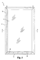
- Membrane electrode assembly 11 includes an internal electrode 12, and an enclosure enclosing the electrode. Assembly 11 further includes a membrane 13, and at least one additional structural element in the enclosure. In the illustrated assembly 11, the enclosure also includes four strip elements 14 arranged around the membrane 13 and electrode 12. Strip elements 14 in general wrap around the membrane 13 and the electrode 12, and a bonding agent can be employed at the contact locations in order to provide a seal.
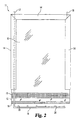
- FIG. 2 shows a partial cut-away of the assembly 11 at various locations in order to reveal layers within.
- Membrane 13 provides the outermost layer, and is separated from electrode 12 by a separating layer 15 formed of a suitable non-conductive material such as a plastic mesh. Separating layer 15 insures that membrane 13 does not contact electrode 12 which may result in undesired degradation of membrane 13.
- insulative layer 16 Located behind electrode 12 is insulative layer 16 made from a non-electrically-conductive material. Insulative layer 16 may, for example, be provided by a non-conductive substance painted or applied to the rear surface of the electrode 12. Layer 16 may also be provided by any other suitable non-conductive layer or material that can be used to electrically isolate electrode 12.
- Strip elements 14 encompass and wrap around membrane 13, separating layer 15, electrode 12, and insulating layer 16. In this fashion, electrode 12 is provided within an enclosure separated from the paint or other liquid medium in the electrodeposition bath by membrane 13.
- membrane electrode assembly 11 is also provided with a system for circulating fluid across the inner surface 13a of the membrane 13 in order to prevent undesirable accumulation of materials at the surface 13a.
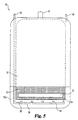
- Figure 3 provides a cross-sectional view taken along line 3-3 of Figure 1 and viewed in the direction of the arrows.
- Assembly 11 includes a fluid inlet tube 17 and a fluid outlet tube 18 for circulating fluid within the enclosure of the membrane electrode assembly 11.
- fluid inlet tube 17 circulates fluid to the bottom of the assembly 11, and has an outlet manifold 19 with multiple outlets 20 for causing the fluid to pass upwardly in the assembly 11.
- Outlets 20 are positioned to cause fluid flow between the membrane 13 and the separating layer 15. In this fashion, fluid is circulated against the inner surface 13a of the membrane 13 to facilitate removal of any materials becoming deposited thereon.
- Membrane electrode cell 30 includes an electrode 31 preferably made of a suitable metal, enclosed by a membrane 32, preferably an ion exchange membrane.
- Electrode 30 includes a first membrane layer 32 and a porous spacer element 33 residing immediately adjacent membrane layer 32 and separating layer 32 from the electrode 31.
- Electrode cell 30 also includes a second spacer element 34 which separates electrode 31 from another layer 32A of membrane material similar to that in membrane layer 32.
- Membrane layers 32 and 32A are sealed together about their peripheries, for example by heat welding or the like.
- Electrode cell 30 also includes an electrolyte circulation system including an inlet tube 35 which extends from the top of the cell to a location adjacent the bottom, and an electrolyte exit tube 36.
- Inlet tube 35 is connected to a laterally-extending baffle tube 38 which in turn has several fluid delivery tubes 39 extending therefrom and opening into the interior of the cell.
- electrolyte passed through inlet tube 35 and baffle tube 38 exits from the various outlet tubes 39 and creates an upward flow of electrolyte within the cell 30, ultimately exiting via outlet tube 36.
- Electrode cell 30 also includes a hanging bracket 37 from which the cell 30 can be suspended in a paint bath.
- the electrode cell 30 is completely sealed apart from the inlet and outlet openings 35 and 36.
- the upper end of the electrode cell 30 may be left unsealed, and the electrode cell 30 suspended in the paint bath such that any unsealed portions are above the level of the bath.
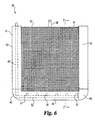
- membrane electrode cell 40 is similar in design to membrane electrode cell 11 illustrated in Figures 1-3.
- membrane electrode cell 40 includes a frame 41 constructed from tubular elements, for example, polymer tubing, including polyvinylchloride (PVC) tubing.
- Frame 41 as depicted includes two vertically extending tubular elements 42 and 43 and a horizontally extending element 44 all interconnected by curved or elbow sections 45 and 46. It will be understood that frame 41 could also be made of fewer pieces or a single piece of tubing configured to an appropriate shape.
- electrode cell frame 41, outermost membrane guard 47, and hanging bracket 48 are also shown in phantom.
- the electrolyte distribution system including an inlet tube 49, a lateral tube 50 providing a manifold, and several outlet tubes 51.
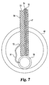
- FIG. 7 shown is a partial cut-away cross-sectional view taken along line 7-7 of Figure 6 and viewed in the direction of the arrows.
- Shown is lateral tube 44 of cell frame 41.
- the lateral electrolyte distribution tube 50 with electrolyte outlet tube 51 extending therefrom.
- Electrolyte tube 51 extends through an aperture 52 provided through the electrode 53.
- a spacer element 54 separating an ion exchange membrane 55 from the electrode 53.
- a nonconductive or otherwise insulating layer 56 is provided on the back side of electrode 53 to insulate the same from the paint bath.
- the electrode 53 along with the spacer 54, membrane 55 and guard 47 all penetrate a location in the tube 44.
- tubular frame 41 serves to support these structures.
- the penetration of the tube 44 and in other locations of the frame 41 is sealed fluid tight.
- the cell 40 is suspended into the paint bath using bracket 48, with the upper edge 57 of the electrode 53 and associated guard, membrane and spacer remaining above the surface of the paint bath. Electrolyte is circulated through tube 49 thus exiting outlets 51 and flowing through apertures 52 in the anode thereby reaching the front surface of the anode and circulating upwardly in the cell in between the anode 53 and the membrane 55.
- membrane electrode cell 40 provides a convenient, inexpensive electrode for use in paint baths and other similar applications.
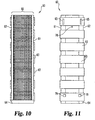
- Membrane electrode cell 60 generally includes a pair of elongate rails 61 and 62 interconnected to one another by a plurality of cross-brace members 63.
- the rails 61 and 62 terminate in a bottom end cap 64.
- a pair of support brackets 65 are attached to uppermost cross-brace member 63 and are used to suspend the membrane electrode cell 60 from a rail or other supporting device located adjacent to the edge of a paint bath.
- Cell 60 also includes an electrode and associated support, spacer, membrane and guard elements all having an arcuate shape, preferably in the shape of a section of a circle, such as a semi-circle.
- FIG 12 shown is an enlarged cross-sectional view taken along line 12-12 of Figure 9 and viewed in the direction of the arrows. Shown are the rails 61 and 62 which each have inner groves 67 and outer groves 68. Received within inner grove 67 are the ends of a support panel 69 extending the length of the cell 60 and having a generally arcuate cross-section. Ends of support panel 69 can be secured into grooves 67 with any suitable welding, bonding or other attachment technique. Immediately adjacent to support panel 69 is an electrode 70, such as an anode, which is received upon support member 69 but not received within grooves 67.
- an electrode 70 such as an anode
- electrode 70 in the completed cell 60 can be removed from the cell 60 and replaced, repaired, etc., if desired.
- membrane spacer 71 and ion exchange membrane 72 are also shown in Figure 12, with the membrane spacer 71 protecting against contact of the membrane 72 and the electrode 70.
- membrane guard 73 which protects membrane 72 against damage resulting from contact with articles during shipment or use.
- Cap 64 is generally arcuate in shape and includes a plurality of arcuate channels therein.
- a first channel 74 receives a combination of the spacer 71, membrane 72 and guard 73. These layers can be bonded within channel 74 using a suitable epoxy or other bonding agent.
- Cap 64 also includes generally arcuate channel 75 for receiving support panel 69 which likewise is bonded within channel 75.
- Cap 64 further includes a channel 76 which is configured to deliver fluid in between the anode 70 and the membrane 72, such as an electrolyte fluid.
- FIG. 14 With reference now to Figure 14 as well, provided is a side view of the section taken along line 14-14 of Figure 13 and viewed in the direction of the arrows. Fluid is provided to channel 76 via bore 77.
- channel 76 extends more deeply into the cap 64 than channels 67 and 68, and bore 77 is located at a level below channels 67 and 68 so as not to intersect them and terminate into the lowermost portion of channel 76.
- electrolyte liquid can be delivered through bore 77 and exit into channel 76, thereafter traveling upwardly in the cell in between anode 70 and membrane 72, traversing its way through the membrane guard 71 which is configured so as to allow its passage.
- membrane cell 60 is immersed in the paint bath, and a potential difference is applied between the electrode (anode) 70 and the counter-electrode article to be coated.
- the upper end of cell 60 can be left open and kept at a level above the level of the paint bath. Alternatively, the upper end of the cell 60 could be closed and means provided for the escape of any gases generated during operation.
- cell 60 can also be equipped with an outlet opening 78 such that electrolyte flowing through cell 60 exits from the outlet opening and can be routed conventionally to a treatment or disposal tank or the like.
- membrane electrode cell 80 may generally have components as described in U.S. Patent No. 5,591,316 issued January 7, 1997, which is hereby incorporated by reference in its entirety.
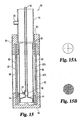
- Membrane electrode cell 80 generally includes a membrane shell including a neck 81 having attached thereto an electrolyte exit tube 82. Neck 81 is glued into collar 83. It will be understood in this regard that neck 81 and collar 83 may also be provided as a single, integral piece.
- Cell 80 also includes a cap 84 at the bottom end of the cell 80, and a membrane guard 85 fashioned in such a manner that its inside diameter fits snugly over collar 83 and cap 84, with guard 85 attached to collar and cap by epoxy or other suitable adhesives, or by welding, for example.
- the membrane shell also includes a membrane 86, e.g. an ion-exchange membrane, encased within cloth layers 87A and 87B, and an inner porous guard tube 88 adjacent thereto. Membrane 86 and its adjacent cloth layers 87A and 87B, and inner porous tube 88 are affixed within grooves defined in collar 83 and cap 84 using epoxy or any other suitable means.
- Membrane electrode cell 80 also includes a tubular electrode 89 disposed within the membrane shell. Electrode 89 will serve as an anode, or cathode, depending upon the type of electradeposition painting to be undertaken, as would be understood by those skilled in the art. Electrode 89 will typically be made of metal or another suitable conductive material. A preferred material is stainless steel. An electrolyte inlet tube 90 extends into the membrane shell and through the interior of the tubular electrode 89, ultimately terminating in an internal electrode cap 91. In use, electrolyte fluid is passed through tube 90 and exits the bottom of cap 91 thereafter flowing upwardly in the membrane shell between the outer surface of electrode 89 and the inner surface of membrane 86 and its accompanying cloth layers.
- a valve 94 is provided in fluid association with the electrolyte supply tube 90, and adapted to allow fluid flow into supply tube 90, and to resist fluid flow out of electrolyte tube 90.
- this may be provided by the inclusion of a three-way or "T" connector 92 situated within the electrolyte supply tube 90, having affixed within its horizontally-extending leg a section of PVC or other tubing 93.
- One-way valve 94 is trapped at the shoulder of the connection of tube 93 and "T" connector 92.
- Figures 15A and 15B illustrate one suitable one-way valve for use in the invention.
- valve 94 including a flexible membrane 95 having a slit pattern 96 cut therein.
- FIG 15B shown is a rear view of the valve depicted in Figure 15A, revealing backing screen 97 associated with one side of the valve 94.
- Such valves are conventional in the art and these and other suitable one-way or check valves of a variety of designs, including for example flap valves or ball-cage valves, will be suitable for use in the present invention.
- valve 94 facilitates this operation by allowing fluid trapped within the interior of electrode 89 to drain into the membrane shell as electrode 89 is being lifted out of the membrane shell, with valve 94 opening in response to increased liquid pressure generated at the exterior of the valve. This avoids the need of lifting large amounts of water when removing electrode 89 from the cell 80.
- This feature is especially advantageous in electrode cells 80 having electrodes 89 having relatively large internal diameters, for example greater than about 4 inches, and typically in the range of about 4 or 5 inches up to about 8 inches ID.
- valve 94 could be incorporated in other positions allowing fluid communication between the interior of the electrode 89 and the membrane shell.
- valve 94 could be positioned in internal cap 91.
Landscapes
- Engineering & Computer Science (AREA)
- Chemical & Material Sciences (AREA)
- Water Supply & Treatment (AREA)
- Chemical Kinetics & Catalysis (AREA)
- Health & Medical Sciences (AREA)
- Urology & Nephrology (AREA)
- Electrochemistry (AREA)
- Materials Engineering (AREA)
- Metallurgy (AREA)
- Organic Chemistry (AREA)
- Separation Using Semi-Permeable Membranes (AREA)
- Water Treatment By Electricity Or Magnetism (AREA)
Applications Claiming Priority (2)
| Application Number | Priority Date | Filing Date | Title |
|---|---|---|---|
| US443303 | 1989-11-29 | ||
| US10/443,303 US7422673B2 (en) | 2003-05-22 | 2003-05-22 | Membrane electrode assemblies and electropaint systems incorporating same |
Publications (1)
| Publication Number | Publication Date |
|---|---|
| EP1486589A1 true EP1486589A1 (de) | 2004-12-15 |
Family
ID=33299578
Family Applications (1)
| Application Number | Title | Priority Date | Filing Date |
|---|---|---|---|
| EP04252981A Withdrawn EP1486589A1 (de) | 2003-05-22 | 2004-05-21 | Membranelektrodenanordnungen und diese enthaldende Vorrichtung zur Elektrotauchlackierung |
Country Status (2)
| Country | Link |
|---|---|
| US (3) | US7422673B2 (de) |
| EP (1) | EP1486589A1 (de) |
Families Citing this family (6)
| Publication number | Priority date | Publication date | Assignee | Title |
|---|---|---|---|---|
| US7422673B2 (en) * | 2003-05-22 | 2008-09-09 | Ufs Corporation | Membrane electrode assemblies and electropaint systems incorporating same |
| US7244342B2 (en) * | 2004-06-28 | 2007-07-17 | Brian Wood | Membrane electrode system for electro coating |
| US20070235324A1 (en) * | 2006-04-07 | 2007-10-11 | Timothy Clark Walker | Membrane electrode assembly incorporating unified encapsulation and electrocoat paint systems incorporating the same |
| JP4873695B2 (ja) * | 2006-04-14 | 2012-02-08 | ダイソー株式会社 | 電着塗装用膜付き中空電極 |
| CN107604418A (zh) * | 2017-09-30 | 2018-01-19 | 合肥凯华环保科技有限公司 | 一种新型管式电泳阳极膜 |
| CN111731026A (zh) * | 2019-08-27 | 2020-10-02 | 南京林业大学 | 一种美术类图画装裱工艺 |
Citations (6)
| Publication number | Priority date | Publication date | Assignee | Title |
|---|---|---|---|---|
| US3419488A (en) * | 1964-04-08 | 1968-12-31 | Ici Ltd | Electro-deposition of paint using an ion exchange membrane |
| EP0392705A1 (de) * | 1989-04-10 | 1990-10-17 | Poly Techs Inc. | Elektrotauchlackieranlage |
| EP0415577A2 (de) * | 1989-08-09 | 1991-03-06 | Poly Techs Inc. | Elektrotauchlackieranlage |
| US5213671A (en) * | 1991-04-01 | 1993-05-25 | Ufs Corporation | Membrane guard for a membrane electrode cell |
| WO2000026445A2 (en) * | 1998-10-30 | 2000-05-11 | Pti Advanced Filtration Inc. | Enhanced membrane electrode devices useful for electrodeposition coating |
| WO2002016675A2 (en) * | 2000-08-24 | 2002-02-28 | Pti Advanced Filtration, Inc. | Enhanced electro-deposition device and method |
Family Cites Families (20)
| Publication number | Priority date | Publication date | Assignee | Title |
|---|---|---|---|---|
| US3620955A (en) * | 1969-05-16 | 1971-11-16 | Carrier Engineering Co Ltd | Cathode cell |
| US3945900A (en) | 1972-05-02 | 1976-03-23 | Dorr-Oliver Incorporated | Electro ultrafiltration process and apparatus |
| FR2240765B1 (de) | 1973-08-16 | 1978-01-27 | Nickel Le | |
| US4075069A (en) | 1975-04-10 | 1978-02-21 | Mitsui Mining & Smelting Co., Ltd. | Processes for preventing the generation of a mist of electrolyte and for recovering generated gases in electrowinning metal recovery, and electrodes for use in said processes |
| CA1092056A (en) | 1977-10-11 | 1980-12-23 | Victor A. Ettel | Electrowinning cell with bagged anode |
| US4212337A (en) | 1978-03-31 | 1980-07-15 | Union Carbide Corporation | Closure fastening device |
| US4363345A (en) | 1980-06-02 | 1982-12-14 | Union Carbide Corporation | Reclosable container |
| US4515674A (en) | 1981-08-07 | 1985-05-07 | Toyota Jidosha Kabushiki Kaisha | Electrode for cationic electrodeposition coating |
| JPS6033915B2 (ja) | 1982-11-16 | 1985-08-06 | 株式会社ポリテツクス | 電着塗装装置 |
| JPS59193299A (ja) | 1983-04-15 | 1984-11-01 | Toyota Motor Corp | カチオン電着塗装装置 |
| US4663016A (en) | 1984-04-30 | 1987-05-05 | Toyota Jidosha Kabushiki Kaisha | Apparatus for electrodeposition coating |
| US4879013A (en) | 1986-03-03 | 1989-11-07 | Ppg Industries, Inc. | Method of cationic electrodeposition using dissolution resistant anodes |
| JP2623092B2 (ja) * | 1987-07-25 | 1997-06-25 | 株式会社 ポリテックス | 電着塗装用隔膜電極装置 |
| US5049253A (en) * | 1988-12-16 | 1991-09-17 | Tokuyama Soda Kabushiki Kaisha | Electrode apparatus for dialysis |
| US4933051A (en) | 1989-07-24 | 1990-06-12 | Omi International Corporation | Cyanide-free copper plating process |
| US5507929A (en) | 1994-07-21 | 1996-04-16 | Koch Membrane Systems, Inc. | Submergible electrode apparatus for dialysis |
| US5759371A (en) | 1996-07-09 | 1998-06-02 | Ufs Corporation | Electrocoat painting overload protection circuit and method |
| JP2000144495A (ja) * | 1998-11-12 | 2000-05-26 | Poritekkusu:Kk | 電着塗装装置 |
| US6713291B2 (en) * | 1999-01-28 | 2004-03-30 | Alan D. King | Electrodes coated with treating agent and uses thereof |
| US7422673B2 (en) * | 2003-05-22 | 2008-09-09 | Ufs Corporation | Membrane electrode assemblies and electropaint systems incorporating same |
-
2003
- 2003-05-22 US US10/443,303 patent/US7422673B2/en not_active Expired - Fee Related
-
2004
- 2004-05-21 EP EP04252981A patent/EP1486589A1/de not_active Withdrawn
-
2006
- 2006-10-31 US US11/590,180 patent/US7897021B2/en not_active Expired - Fee Related
-
2008
- 2008-09-08 US US12/206,272 patent/US8083919B2/en not_active Expired - Fee Related
Patent Citations (8)
| Publication number | Priority date | Publication date | Assignee | Title |
|---|---|---|---|---|
| US3419488A (en) * | 1964-04-08 | 1968-12-31 | Ici Ltd | Electro-deposition of paint using an ion exchange membrane |
| EP0392705A1 (de) * | 1989-04-10 | 1990-10-17 | Poly Techs Inc. | Elektrotauchlackieranlage |
| EP0415577A2 (de) * | 1989-08-09 | 1991-03-06 | Poly Techs Inc. | Elektrotauchlackieranlage |
| US5213671A (en) * | 1991-04-01 | 1993-05-25 | Ufs Corporation | Membrane guard for a membrane electrode cell |
| US5468361A (en) * | 1991-04-01 | 1995-11-21 | Ufs Corporation | Membrane guard for a membrane electrode cell |
| US5591316A (en) * | 1991-04-01 | 1997-01-07 | Ufs Corporation | Electrocoat painting method using guarded tubular membrane electrode cells |
| WO2000026445A2 (en) * | 1998-10-30 | 2000-05-11 | Pti Advanced Filtration Inc. | Enhanced membrane electrode devices useful for electrodeposition coating |
| WO2002016675A2 (en) * | 2000-08-24 | 2002-02-28 | Pti Advanced Filtration, Inc. | Enhanced electro-deposition device and method |
Also Published As
| Publication number | Publication date |
|---|---|
| US20090000945A1 (en) | 2009-01-01 |
| US20040231992A1 (en) | 2004-11-25 |
| US8083919B2 (en) | 2011-12-27 |
| US20070039825A1 (en) | 2007-02-22 |
| US7897021B2 (en) | 2011-03-01 |
| US7422673B2 (en) | 2008-09-09 |
Similar Documents
| Publication | Publication Date | Title |
|---|---|---|
| US8083919B2 (en) | Membrane electrode assemblies and electropaint systems incorporating same | |
| JP4230569B2 (ja) | 中空糸膜モジュール | |
| EP0153928A1 (de) | In-linie filter. | |
| JP2623092B2 (ja) | 電着塗装用隔膜電極装置 | |
| US20040112752A1 (en) | EDI device with resin seepage-proof inserts | |
| US5591316A (en) | Electrocoat painting method using guarded tubular membrane electrode cells | |
| EP1133589B1 (de) | Verbesserte membran-elektrodeneinheiten für elektrotauchlackierung | |
| JPH08158084A (ja) | 電解槽 | |
| US5507929A (en) | Submergible electrode apparatus for dialysis | |
| EP0833963A1 (de) | Membranelement für eine elektrolytische filterpresse | |
| CA2214917A1 (en) | Process for control of electrodeposition utilizing cathodic and anodic flushable electrodes | |
| JP2816029B2 (ja) | 複極式フィルタープレス型電解槽 | |
| CN217646193U (zh) | 一种卷式扩散渗析组件 | |
| CN219168139U (zh) | 一种电渗析电极隔室 | |
| JPH0725212Y2 (ja) | 浸漬型膜モジュール | |
| CN220985984U (zh) | 一种防水机柜 | |
| CN215626975U (zh) | 一种电渗析的滤芯桶结构及电渗析滤芯 | |
| JPH08371Y2 (ja) | 電着塗装用の隔膜電極 | |
| CN212039876U (zh) | 一种新型电泳涂装超滤设备 | |
| CN218026407U (zh) | 一种用于电泳超滤设备停电防冒槽子的装置 | |
| EP1377361A1 (de) | Rohrförmige membranelektrode für den einsatz in elektrodialyse und elektrobeschichtung | |
| JPS6130806B2 (de) | ||
| JP3319939B2 (ja) | アルカリイオン水生成器 | |
| JP2527168Y2 (ja) | 電着塗装用の隔膜電極構造 | |
| US20070235324A1 (en) | Membrane electrode assembly incorporating unified encapsulation and electrocoat paint systems incorporating the same |
Legal Events
| Date | Code | Title | Description |
|---|---|---|---|
| PUAI | Public reference made under article 153(3) epc to a published international application that has entered the european phase |
Free format text: ORIGINAL CODE: 0009012 |
|
| AK | Designated contracting states |
Kind code of ref document: A1 Designated state(s): AT BE BG CH CY CZ DE DK EE ES FI FR GB GR HU IE IT LI LU MC NL PL PT RO SE SI SK TR |
|
| AX | Request for extension of the european patent |
Extension state: AL HR LT LV MK |
|
| 17P | Request for examination filed |
Effective date: 20050615 |
|
| AKX | Designation fees paid |
Designated state(s): AT BE BG CH CY CZ DE DK EE ES FI FR GB GR HU IE IT LI LU MC NL PL PT RO SE SI SK TR |
|
| STAA | Information on the status of an ep patent application or granted ep patent |
Free format text: STATUS: THE APPLICATION IS DEEMED TO BE WITHDRAWN |
|
| 18D | Application deemed to be withdrawn |
Effective date: 20101013 |