EP1486598A2 - Tissu métallique et méthode de fabrication - Google Patents
Tissu métallique et méthode de fabrication Download PDFInfo
- Publication number
- EP1486598A2 EP1486598A2 EP04011532A EP04011532A EP1486598A2 EP 1486598 A2 EP1486598 A2 EP 1486598A2 EP 04011532 A EP04011532 A EP 04011532A EP 04011532 A EP04011532 A EP 04011532A EP 1486598 A2 EP1486598 A2 EP 1486598A2
- Authority
- EP
- European Patent Office
- Prior art keywords
- metal mesh
- light guide
- coupling
- light
- fabric
- Prior art date
- Legal status (The legal status is an assumption and is not a legal conclusion. Google has not performed a legal analysis and makes no representation as to the accuracy of the status listed.)
- Withdrawn
Links
Images

Classifications
-
- D—TEXTILES; PAPER
- D03—WEAVING
- D03D—WOVEN FABRICS; METHODS OF WEAVING; LOOMS
- D03D15/00—Woven fabrics characterised by the material, structure or properties of the fibres, filaments, yarns, threads or other warp or weft elements used
- D03D15/60—Woven fabrics characterised by the material, structure or properties of the fibres, filaments, yarns, threads or other warp or weft elements used characterised by the warp or weft elements other than yarns or threads
- D03D15/67—Metal wires
-
- D—TEXTILES; PAPER
- D03—WEAVING
- D03D—WOVEN FABRICS; METHODS OF WEAVING; LOOMS
- D03D15/00—Woven fabrics characterised by the material, structure or properties of the fibres, filaments, yarns, threads or other warp or weft elements used
- D03D15/50—Woven fabrics characterised by the material, structure or properties of the fibres, filaments, yarns, threads or other warp or weft elements used characterised by the properties of the yarns or threads
- D03D15/547—Woven fabrics characterised by the material, structure or properties of the fibres, filaments, yarns, threads or other warp or weft elements used characterised by the properties of the yarns or threads with optical functions other than colour, e.g. comprising light-emitting fibres
-
- D—TEXTILES; PAPER
- D10—INDEXING SCHEME ASSOCIATED WITH SUBLASSES OF SECTION D, RELATING TO TEXTILES
- D10B—INDEXING SCHEME ASSOCIATED WITH SUBLASSES OF SECTION D, RELATING TO TEXTILES
- D10B2101/00—Inorganic fibres
- D10B2101/20—Metallic fibres
Definitions
- the invention relates to a metal mesh and a method for producing Metal fabric.
- Metal mesh is used for a variety of tasks. Amongst other things they are used on buildings, for example as facade curtains, as a room divider and / or as the immediate outer skin of a building.
- a relatively dense metal mesh is required or sought for aesthetic reasons.
- a relative high density of the fabric may be required if this is in the static Structure is integrated and therefore must bear loads.
- Fabric as permanent burglar-proof devices in front of windows, can also be used on private houses.
- the invention has for its object to such a metal mesh To provide that it has the effect of darkening inherent in metal mesh decreases or even completely at a given tissue density balances.
- the fabric area is defined by the warp and Weft threads of the metal mesh.
- the fabric surface be a level.
- the arrangement of a light guide body makes an active light connection made between the two sides of the fabric surface. So is on light captured on one side and at least partially directed to the other side and can be emitted there in a targeted or untargeted manner.
- the one through the Shadowing caused by light absorption of the metal fabric elements The darkening effect can at least be reduced and especially suitable arrangement of the light guide body, in particular a plurality of light guide bodies and / or particularly suitable illumination of one side of the fabric even almost completely compensated by the bundled light transmission become.
- the mathematical area with the thickness is the main area of the fabric Understood zero, which can be thought in the middle of the tissue.
- Usually generic metal meshes are distinctly two-dimensional and have a relatively small thickness.
- the metal mesh has on its Lichtleit emotions a light coupling area and a light coupling area on, wherein at least one of the coupling areas from the fabric surface protrudes outwards.
- Any area is a light coupling area understood on the surface of the light-guiding body, on which light can penetrate into the body from outside the light guide body. Analogous any area of the surface should be understood as a light decoupling area, at what light, which is guided inside the body, this under Refraction or linear to the outside.
- the coupling area can even come from the surface of the metal mesh protrude, with a suitable design of the coupling area this at least a hemispherical area in direct Line of sight has, without warp and / or weft threads the view, so any light line, block. This can also be done at large angles of incidence of light captured and bundled to the other side be transmitted.
- both coupling areas protrude from the fabric surface on opposite sides.
- a particularly large-angle effective space is available.
- the coupling areas even protrude beyond the fabric surface, can, with a suitable design, light from an entire room side of the metal mesh to the entire other side of the metal mesh become. In the end, this only depends on the light guide paths inside of the light guide body.
- At least one Coupling area a coupling surface offset angularly to the fabric surface having.
- the coupling surface offset at an angle can cover the entire coupling area make up this side of the light guide body.
- a coupling area has several coupling surfaces. These can even be arranged at different angles to the tissue surface. hereby this results in a particularly uniform or at least multifaceted light coupling or light decoupling.
- the coupling area has several coupling surfaces, these can be advantageously at least partially adjoin one another. In one such a case does not lie between two coupling surfaces of a coupling area necessarily dead areas. Therefore, all of the light that passes between the outer boundaries of the two adjacent coupling surfaces hits, also coupled or uncoupled. Scattered radiation and Light absorption on the light guide body is minimized in this way.
- the coupling areas can be paired for particularly effective light conduction communicating coupling and decoupling surfaces with one have essentially the same angular position to the tissue plane in pairs.
- the communicating with each other Coupling surfaces are roughly parallel, so that light, which over the coupling surface is coupled into the light guide, approximately parallel to its original beam direction on the decoupling surface again is coupled out, provided there are no further refractions inside the light guide body or reflections take place.
- Especially with a large number of pairs communicating coupling and decoupling surfaces on one Light guide body can therefore be guaranteed that light which in the area of the light guide body meets the metal mesh, this approximately penetrates as if there were no obstacle in the beam path. The This means that the natural direction of light can be retained. In the beam path there is only an offset inside the light guide body, the offset approximately to the thickness of the tissue to the light beam other side.
- the light guide body at least with respect to the tissue plane is constructed and / or arranged essentially symmetrically.
- the orientation of the tissue becomes largely irrelevant, there is not a side that has to serve to couple the light, and one that must be used to extract the light.
- the fabric can be installed anywhere.
- an im Essentially axisymmetric light guide body with its axis of symmetry be arranged in the fabric surface so that on both sides of the fabric protrude approximately equal parts of the light guide body.
- the fabric looks optically neutral without light, with a special one Light exposure but colored, it is proposed that the light guide is colorless but prismatic.
- a light-guiding body of the proposed type is already in use kind in a metal mesh that brings the mentioned advantages.
- a metal mesh with a variety of light guide bodies of the type described, which preferably regularly to each other are arranged in the tissue. This not only improves conductivity, but also the visual effect of the fabric with or without Light.
- These are particularly suitable for capturing, guiding and emitting light Dimensions crystal structures. These can be colored, but especially also be colorless plastic or glass, which among other things an inexpensive Manufacturing enables.
- Such light guide bodies can also be used depending on their attractiveness subject to being stolen by passers-by.
- a conglomerate made of metal mesh and artificial crystals in a joint exhibition of the three companies GKD AG, Düren, Nagel-Hammers, Wesseling, both DE, and D. Swarovski & Co., Wattens, AT.
- the artificial crystals with small clamps on one side of a metal mesh on the weft bars attached. In this way, an optical effect is created, in which Viewing light from 124 halogen spotlights resolved in spectral colors of 20 watts each is demonstrated.
- the halogen spotlights are controlled by a computer changes over time; however, the viewer stands on it Side of the fabric as the light sources, since only the reflective properties of the metal mesh in connection with the reflective properties of the crystals are used. On the back of the crystal-metal mesh conglomerate there is a very strong darkening in the exhibition.
- a metal mesh light guide body in particular crystals, structurally integrated are.
- the crystals can be on a wire or a other carrier threaded and in several places with the shot or in particular be connected to the chain of the metal mesh.
- the crystals can be on a wire or a other carrier threaded and in several places with the shot or in particular be connected to the chain of the metal mesh.
- the crystals can be on a wire or a other carrier threaded and in several places with the shot or in particular be connected to the chain of the metal mesh.
- the carrier wire of the crystals or one Clamp that connects the carrier wire to the metal mesh.
- Such a fabric is then particularly secured against theft, if a separation of the light guide body from the carrier is a solution of the Carrier of the tissue.
- the carrier wire essentially placed perpendicular to the warp threads as deep as possible in the fabric surface and is fastened there, especially at intersections of grouped, opposite warp threads.
- a combined metal-fiber optic fabric can be used Factory completed and transported in this form to the installation site become. Larger areas, for example connected fabrics in the size of entire facade fronts, can be easily also stack.
- the present invention opens up new fields of use for metal mesh.
- metal mesh can also be lettering, company identification or the like permanently and securely integrated in a metal mesh.
- the fabric can also be used where there are light-guiding properties are explicitly required, for example with lampshades.
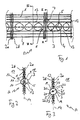
- the metal mesh A in Figures 1 to 3 initially consists of weft wires 1 and warp wires 2a, 2b, which together in a known manner are interwoven.
- glass crystals 3 are integrated in the fabric A.
- the glass crystals 3 are each provided with a threading channel 5 and serially threaded onto a carrier wire 4.
- the carrier wire 4 is thereby integrated into the fabric that it takes up the course 11 of a removed weft wire. As a result, he stabilizes the warp wires 2a, 2b and is simultaneously in the Fixed height.
- Such integration into the tissue is structurally optimal and at the same time enables an absolutely symmetrical arrangement the glass crystals 3 with respect to a tissue plane 14. Disadvantageously but the glass crystals 3 are transported to their target position before they are threaded. So a high level of precision is required with that when threading the carrier wire 4 cleanly pass through the threading channels 5 can.
- glass crystals 3 are in a free space in the metal mesh B inserted by removing two weft wires 1. There If there is an even number of weft wires, the neighboring ones are located Weft wires 13 on different sides 17, 18 of the warp wires 2. In this respect there is only a slight risk that the weft wires 1 along the tissue plane 14 could slip between the warp wires 2. Rather would they wedge between the warp wires 2.
- the carrier wires 4 are deep in the tissue B inserted structural connection points 6 and there by a Side of fabric B with warp wires 2 after weaving the fabric B connected.
- this can be advantageous because the assembly of the metal mesh and the threaded glass crystals so much cheaper and faster can go.
Landscapes
- Engineering & Computer Science (AREA)
- Textile Engineering (AREA)
- Woven Fabrics (AREA)
Applications Claiming Priority (4)
| Application Number | Priority Date | Filing Date | Title |
|---|---|---|---|
| DE10326655 | 2003-06-11 | ||
| DE10326655 | 2003-06-11 | ||
| DE10343664A DE10343664A1 (de) | 2003-06-11 | 2003-09-18 | Metallgewebe und Verfahren zum Herstellen eines Metallgewebes |
| DE10343664 | 2003-09-18 |
Publications (2)
| Publication Number | Publication Date |
|---|---|
| EP1486598A2 true EP1486598A2 (fr) | 2004-12-15 |
| EP1486598A3 EP1486598A3 (fr) | 2005-09-14 |
Family
ID=33300852
Family Applications (1)
| Application Number | Title | Priority Date | Filing Date |
|---|---|---|---|
| EP04011532A Withdrawn EP1486598A3 (fr) | 2003-06-11 | 2004-05-14 | Tissu métallique et méthode de fabrication |
Country Status (6)
| Country | Link |
|---|---|
| US (1) | US7072567B2 (fr) |
| EP (1) | EP1486598A3 (fr) |
| JP (1) | JP2005002551A (fr) |
| CN (1) | CN1572936A (fr) |
| CA (1) | CA2470613A1 (fr) |
| RU (1) | RU2004117753A (fr) |
Cited By (3)
| Publication number | Priority date | Publication date | Assignee | Title |
|---|---|---|---|---|
| WO2007054064A1 (fr) * | 2005-11-08 | 2007-05-18 | Gkd - Gebr. Kufferath Ag | Tissu a fils de trame |
| EP1887279A2 (fr) | 2006-08-11 | 2008-02-13 | Haver & Boecker oHG | Tissu illuminé et méthode de fabrication associée |
| CN101356307B (zh) * | 2005-11-08 | 2013-06-12 | Gkd-吉伯.库费拉思股份公司 | 具有纬线的织物及其应用与用于安装建筑物悬挂物的方法 |
Families Citing this family (7)
| Publication number | Priority date | Publication date | Assignee | Title |
|---|---|---|---|---|
| US8126814B2 (en) * | 2004-11-18 | 2012-02-28 | Cisco Technology, Inc. | Method and system for installing software and hardware feature licenses on devices |
| US8021020B2 (en) | 2007-07-16 | 2011-09-20 | Cambridge International Inc. | Lighted architectural mesh |
| US20100017735A1 (en) * | 2008-07-15 | 2010-01-21 | Unisys Corporation | Decentralized hardware partitioning within a multiprocessing computing system |
| US8374858B2 (en) * | 2010-03-09 | 2013-02-12 | Dts, Inc. | Scalable lossless audio codec and authoring tool |
| US9091834B2 (en) * | 2013-02-01 | 2015-07-28 | Halliburton Energy Services, Inc. | Fiber splice housing with temperature compensation |
| US11371843B2 (en) * | 2020-07-02 | 2022-06-28 | Anello Photonics, Inc. | Integration of photonics optical gyroscopes with micro-electro-mechanical sensors |
| CN113985544A (zh) * | 2021-09-29 | 2022-01-28 | 杭州富通通信技术股份有限公司 | 一种层绞光缆用金属编织物 |
Family Cites Families (7)
| Publication number | Priority date | Publication date | Assignee | Title |
|---|---|---|---|---|
| DE344697C (fr) | ||||
| US4234907A (en) * | 1979-01-29 | 1980-11-18 | Maurice Daniel | Light emitting fabric |
| DE3525838A1 (de) | 1985-07-02 | 1987-01-22 | Joachim Zappe | Verfahren zum erzielen von leuchteffekten an werkstoffen und daraus gefertigten gegenstaenden |
| JPH0739240B2 (ja) * | 1992-05-06 | 1995-05-01 | 雅子 山上 | 発光装飾織物 |
| DE10012614A1 (de) | 2000-03-15 | 2001-09-27 | Maass Ruth | Leuchtfahne und Fahnenanordnung |
| DE10127299A1 (de) * | 2001-06-06 | 2002-12-12 | Kufferath Geb Gkd | Flächengefüge aus miteinander in regelmäßiger Anordnung in Verbindung stehenden Materialsträngen und Leuchtelement mit einem derartigen Flächengefüge |
| US6793360B2 (en) * | 2002-09-09 | 2004-09-21 | Cambridge, Inc. | Lighted architectural mesh |
-
2004
- 2004-05-14 EP EP04011532A patent/EP1486598A3/fr not_active Withdrawn
- 2004-06-10 US US10/868,444 patent/US7072567B2/en not_active Expired - Fee Related
- 2004-06-10 JP JP2004173024A patent/JP2005002551A/ja active Pending
- 2004-06-10 CA CA002470613A patent/CA2470613A1/fr not_active Abandoned
- 2004-06-11 RU RU2004117753/12A patent/RU2004117753A/ru not_active Application Discontinuation
- 2004-06-11 CN CNA2004100766110A patent/CN1572936A/zh active Pending
Cited By (6)
| Publication number | Priority date | Publication date | Assignee | Title |
|---|---|---|---|---|
| WO2007054064A1 (fr) * | 2005-11-08 | 2007-05-18 | Gkd - Gebr. Kufferath Ag | Tissu a fils de trame |
| EP2116640A1 (fr) * | 2005-11-08 | 2009-11-11 | Mediamesh GBR | Tissu à fils de trames métalliques |
| US8056586B2 (en) | 2005-11-08 | 2011-11-15 | Gkd-Gebr. Kufferath Ag | Woven fabric comprising weft wires |
| CN101356307B (zh) * | 2005-11-08 | 2013-06-12 | Gkd-吉伯.库费拉思股份公司 | 具有纬线的织物及其应用与用于安装建筑物悬挂物的方法 |
| US8726479B2 (en) | 2005-11-08 | 2014-05-20 | GKD—Gebr. Kufferath AG | Woven fabric comprising weft wires |
| EP1887279A2 (fr) | 2006-08-11 | 2008-02-13 | Haver & Boecker oHG | Tissu illuminé et méthode de fabrication associée |
Also Published As
| Publication number | Publication date |
|---|---|
| CA2470613A1 (fr) | 2004-12-11 |
| US7072567B2 (en) | 2006-07-04 |
| JP2005002551A (ja) | 2005-01-06 |
| RU2004117753A (ru) | 2005-11-20 |
| US20050002636A1 (en) | 2005-01-06 |
| CN1572936A (zh) | 2005-02-02 |
| EP1486598A3 (fr) | 2005-09-14 |
Similar Documents
| Publication | Publication Date | Title |
|---|---|---|
| WO2004007887A1 (fr) | Element de fenetre | |
| EP0531982B1 (fr) | Plaque en matière plastique transparente ayant un caractère de protection des oiseaux et son utilisation | |
| WO2024041958A1 (fr) | Agencement de profilés pour la mise en place de stands d'exposition ou d'accessoires de magasin | |
| DE102006037878A1 (de) | Leuchtgewebe und Verfahren zur dessen Herstellung | |
| DE3628540C2 (de) | Zeiger für ein Anzeigeinstrument | |
| DE202008004711U1 (de) | Lichtgitterkaskadierung | |
| US7072567B2 (en) | Metal fabric and method for manufacturing a metal fabric | |
| DE2232114C3 (fr) | ||
| EP0229121A1 (fr) | Procede d'obtention d'effets luminescents sur des matieres textiles | |
| DE10343664A1 (de) | Metallgewebe und Verfahren zum Herstellen eines Metallgewebes | |
| DE3346699A1 (de) | Bewegungsmelder | |
| EP2426240B1 (fr) | Treillage métallique | |
| DE29706568U1 (de) | Beleuchtungsvorrichtung | |
| DE19853931B4 (de) | Lichtumlenkelement zur Tageslichtnutzung | |
| EP0646479A2 (fr) | Panneau décoratif | |
| DE202006019418U1 (de) | Leuchtende Glaswand | |
| DE602004011493T2 (de) | Verfahren zur herstellung elektrischer schilder und elektrisches schild | |
| DE4446435A1 (de) | Vitrine mit einer Beleuchtungseinrichtung | |
| EP1239111B1 (fr) | Tissu pour dispositifs de protection solaire | |
| DE2947719C2 (de) | Retroreflektorplatte | |
| EP3767164B1 (fr) | Dispositif anti-éblouissement | |
| DE8915821U1 (de) | Wand- oder Deckenleuchte | |
| EP1843082B1 (fr) | Plafonnier, en particulier pour utilisation dans un couloir | |
| DE102014113631B3 (de) | Tageslichtsystem | |
| DE102017202931B4 (de) | Profil zum Erstellen von Aufbauten und Aufbau mit wenigstens zwei Profilen |
Legal Events
| Date | Code | Title | Description |
|---|---|---|---|
| PUAI | Public reference made under article 153(3) epc to a published international application that has entered the european phase |
Free format text: ORIGINAL CODE: 0009012 |
|
| AK | Designated contracting states |
Kind code of ref document: A2 Designated state(s): AT BE BG CH CY CZ DE DK EE ES FI FR GB GR HU IE IT LI LU MC NL PL PT RO SE SI SK TR |
|
| AX | Request for extension of the european patent |
Extension state: AL HR LT LV MK |
|
| PUAL | Search report despatched |
Free format text: ORIGINAL CODE: 0009013 |
|
| AK | Designated contracting states |
Kind code of ref document: A3 Designated state(s): AT BE BG CH CY CZ DE DK EE ES FI FR GB GR HU IE IT LI LU MC NL PL PT RO SE SI SK TR |
|
| AX | Request for extension of the european patent |
Extension state: AL HR LT LV MK |
|
| RIC1 | Information provided on ipc code assigned before grant |
Ipc: 7G 02B 6/00 B Ipc: 7D 03D 15/00 A |
|
| AKX | Designation fees paid | ||
| STAA | Information on the status of an ep patent application or granted ep patent |
Free format text: STATUS: THE APPLICATION IS DEEMED TO BE WITHDRAWN |
|
| 18D | Application deemed to be withdrawn |
Effective date: 20060315 |
|
| REG | Reference to a national code |
Ref country code: DE Ref legal event code: 8566 |