EP1488024B1 - Procede et dispositif permettant de former des revetements en ceramique sur des metaux et des alliages - Google Patents
Procede et dispositif permettant de former des revetements en ceramique sur des metaux et des alliages Download PDFInfo
- Publication number
- EP1488024B1 EP1488024B1 EP02765036.5A EP02765036A EP1488024B1 EP 1488024 B1 EP1488024 B1 EP 1488024B1 EP 02765036 A EP02765036 A EP 02765036A EP 1488024 B1 EP1488024 B1 EP 1488024B1
- Authority
- EP
- European Patent Office
- Prior art keywords
- electrolyte
- current
- process according
- frequency
- acoustic
- Prior art date
- Legal status (The legal status is an assumption and is not a legal conclusion. Google has not performed a legal analysis and makes no representation as to the accuracy of the status listed.)
- Expired - Lifetime
Links
Images

Classifications
-
- C—CHEMISTRY; METALLURGY
- C25—ELECTROLYTIC OR ELECTROPHORETIC PROCESSES; APPARATUS THEREFOR
- C25D—PROCESSES FOR THE ELECTROLYTIC OR ELECTROPHORETIC PRODUCTION OF COATINGS; ELECTROFORMING; APPARATUS THEREFOR
- C25D5/00—Electroplating characterised by the process; Pretreatment or after-treatment of workpieces
- C25D5/60—Electroplating characterised by the structure or texture of the layers
- C25D5/615—Microstructure of the layers, e.g. mixed structure
- C25D5/617—Crystalline layers
-
- C—CHEMISTRY; METALLURGY
- C25—ELECTROLYTIC OR ELECTROPHORETIC PROCESSES; APPARATUS THEREFOR
- C25D—PROCESSES FOR THE ELECTROLYTIC OR ELECTROPHORETIC PRODUCTION OF COATINGS; ELECTROFORMING; APPARATUS THEREFOR
- C25D5/00—Electroplating characterised by the process; Pretreatment or after-treatment of workpieces
- C25D5/18—Electroplating using modulated, pulsed or reversing current
-
- C—CHEMISTRY; METALLURGY
- C25—ELECTROLYTIC OR ELECTROPHORETIC PROCESSES; APPARATUS THEREFOR
- C25D—PROCESSES FOR THE ELECTROLYTIC OR ELECTROPHORETIC PRODUCTION OF COATINGS; ELECTROFORMING; APPARATUS THEREFOR
- C25D11/00—Electrolytic coating by surface reaction, i.e. forming conversion layers
- C25D11/005—Apparatus specially adapted for electrolytic conversion coating
-
- C—CHEMISTRY; METALLURGY
- C25—ELECTROLYTIC OR ELECTROPHORETIC PROCESSES; APPARATUS THEREFOR
- C25D—PROCESSES FOR THE ELECTROLYTIC OR ELECTROPHORETIC PRODUCTION OF COATINGS; ELECTROFORMING; APPARATUS THEREFOR
- C25D11/00—Electrolytic coating by surface reaction, i.e. forming conversion layers
- C25D11/02—Anodisation
- C25D11/024—Anodisation under pulsed or modulated current or potential
-
- C—CHEMISTRY; METALLURGY
- C25—ELECTROLYTIC OR ELECTROPHORETIC PROCESSES; APPARATUS THEREFOR
- C25D—PROCESSES FOR THE ELECTROLYTIC OR ELECTROPHORETIC PRODUCTION OF COATINGS; ELECTROFORMING; APPARATUS THEREFOR
- C25D11/00—Electrolytic coating by surface reaction, i.e. forming conversion layers
- C25D11/02—Anodisation
- C25D11/026—Anodisation with spark discharge
-
- C—CHEMISTRY; METALLURGY
- C25—ELECTROLYTIC OR ELECTROPHORETIC PROCESSES; APPARATUS THEREFOR
- C25D—PROCESSES FOR THE ELECTROLYTIC OR ELECTROPHORETIC PRODUCTION OF COATINGS; ELECTROFORMING; APPARATUS THEREFOR
- C25D5/00—Electroplating characterised by the process; Pretreatment or after-treatment of workpieces
- C25D5/20—Electroplating using ultrasonic waves
-
- C—CHEMISTRY; METALLURGY
- C25—ELECTROLYTIC OR ELECTROPHORETIC PROCESSES; APPARATUS THEREFOR
- C25D—PROCESSES FOR THE ELECTROLYTIC OR ELECTROPHORETIC PRODUCTION OF COATINGS; ELECTROFORMING; APPARATUS THEREFOR
- C25D5/00—Electroplating characterised by the process; Pretreatment or after-treatment of workpieces
- C25D5/60—Electroplating characterised by the structure or texture of the layers
- C25D5/605—Surface topography of the layers, e.g. rough, dendritic or nodular layers
- C25D5/611—Smooth layers
-
- C—CHEMISTRY; METALLURGY
- C25—ELECTROLYTIC OR ELECTROPHORETIC PROCESSES; APPARATUS THEREFOR
- C25D—PROCESSES FOR THE ELECTROLYTIC OR ELECTROPHORETIC PRODUCTION OF COATINGS; ELECTROFORMING; APPARATUS THEREFOR
- C25D5/00—Electroplating characterised by the process; Pretreatment or after-treatment of workpieces
- C25D5/627—Electroplating characterised by the visual appearance of the layers, e.g. colour, brightness or mat appearance
Definitions
- the invention relates to the field of applying protective coatings, and in particular to plasma-electrolytic oxidation coating of articles made of metals and alloys. This process makes it possible rapidly and efficiently to form wear-resistant, corrosion-resistant, heat-resistant, dielectric uniformly-coloured ceramic coatings on the surfaces of these articles.
- the coatings are characterised by a high degree of uniformity of thickness, low surface roughness and the virtual absence of an external porous layer, the removal of which usually involves considerable expense in conventional coating processes.
- the process for producing the coatings and the device for implementing the process, described in this application can be used in engineering, the aircraft and motor vehicle industries, the petrochemical and textiles industries, electronics, medicine and the production of household goods.
- a process for producing a ceramic coating using industrial-frequency 50-60Hz current is known from WO 99/31303 .
- the process enables hard coatings of thickness up to 200 ⁇ m, well-bonded to the substrate, to be formed on the surface of articles made from aluminium alloys.
- the main problem with this process is the formation of a considerable external porous layer of low microhardness and with numerous micro- and macro-defects (pores, micro-cracks, flaky patches).
- the thickness of the defective layer amounts to 25-55% of the total thickness of the ceramic coating, depending on the chemical composition of the alloy being processed and on the electrolysis regimes.
- Expensive precision equipment is used to remove the porous layer. If the article is of complex shape, with surfaces that are difficult for abrasive and diamond tools to reach, the problem of removing the defective layer becomes difficult to solve. This limits the range of application of the process.
- a process for forming ceramic coatings where the current has a modified sine wave form is known from US 5,616,229 .
- This form of current reduces heat stresses in forming the ceramic layer and enables coatings of thickness up to 300 ⁇ m to be applied.
- industrial frequency current is used in this process, which leads to the formation of a relatively thick external porous layer with high surface roughness and relatively high energy costs.
- RU 2077612 for oxidising valve metals and alloys in a pulsed anode-cathode regime, in which positive and negative pulses of a special complex form alternate.
- the duration of the pulses and of the pause between a positive pulse and a negative one is 100-130 ⁇ sec, and the succession frequency is 50Hz.
- the current reaches its maximum (up to 800A/dm 2 ), after which it remains constant for 25-50 ⁇ sec.
- the shorter pulses and far greater pulse powers enable the discharge ignition time to be reduced considerably, and the main reasons for the formation of the defective outer layers are eliminated.
- the pairs of powerful pulses alternate with unjustifiably long pauses, which leads to a low coating formation rate.
- the closest prior art to the proposed invention is the process described in RU 2070942 for oxidation using alternating positive and negative pulses of voltage, amplitude 100-500V and duration 1-10 ⁇ sec, during which, at each of the anode half-periods, high-voltage positive pulses, amplitude 600-1000V and duration 0.1-1 ⁇ sec, are also applied.
- the pulses When the pulses are applied, the total current at that moment rises, which creates favourable conditions for discharges.
- the problem with this process is the use of very short high-voltage positive pulses, which does not make it possible to create discharges of sufficient power. This leads to low productivity of the process, and it is also extremely difficult to implement the proposed process technically for industrial purposes.
- WO 01/81658 discloses a method for obtaining a ceramic coating at the surface of a metal, having semiconductor properties, such as aluminium, titanium, magnesium, hafnium, zirconium and their alloys, by physico-chemical reaction transforming the treated metal.
- Said method consists in immersing the metallic piece to be coated in an electrolytic solution consisting of an aqueous solution of alkali metal hydroxide, such as potassium or sodium, and an alkali metal oxyacid salt, the metallic piece forming one of the electrodes, and in applying to the electrodes a signal generally triangular in shape, that is having at least a front slope and a rear slope, with variable shape factor during the process, generating a current controlled in intensity, its shape and its ratio between positive intensity and negative intensity.
- an electrolytic solution consisting of an aqueous solution of alkali metal hydroxide, such as potassium or sodium, and an alkali metal oxyacid salt
- Ceramic coatings formed by the process of the first aspect of the present invention may, without any post-processing, have an external porous layer comprising not more than 14% of a total coating thickness.
- Ceramic coatings formed by the process of the first aspect of the present invention may, without any post-processing, have a surface with a low roughness (Ra) of 0.6 to 2.1 ⁇ m.
- the bipolar current pulses may be alternating pulses, or may be supplied as packets of pulses, for example comprising two of one polarity followed by another of opposed polarity.
- Embodiments of the present invention seek to improve the useful properties of ceramic coatings such as resistance to wear, corrosion and heat, and dielectric strength, by improving the physico-mechanical characteristics of the coatings. Embodiments of the invention also solve the technical problem of producing hard microcrystalline ceramic coatings with good adhesion to a substrate.
- Embodiments of the invention also seek to improve the technical sophistication of the process of forming ceramic coatings by significantly reducing the time it takes to apply the coating itself, and the time spent in the finishing treatment thereof. Not only is the productivity of the oxidation process raised, but specific power costs are also significantly reduced.
- Embodiments of the invention additionally provide for the targeted formation of coatings with set properties by introducing refractory inorganic compounds into the electrolyte.
- Embodiments of the invention may also raise the stability of the electrolyte and increase its useful life.
- Embodiments of the apparatus of the present invention seek to provide improved reliability, versatility and ease of building into automated production lines.
- an article to be coated is connected to an electrode and placed in an electrolytic bath which has another electrode and which is filled with an alkaline electrolyte.
- the electrodes are supplied with pulsed current so as to form a coating of a required thickness in a plasma-electrolytic oxidation regime.
- Pulsed current is created in the bath with a pulse succession frequency of 500Hz or more, preferably 1000 to 10,000Hz, with a preferred pulse duration of 20 to 1,000 ⁇ sec.
- Each current pulse advantageously has a steep front, so that the maximum amplitude is reached in not more than 10% of the total pulse duration, and the current then falls sharply, after which it gradually decreases to 50% or less of the maximum.
- the current density is preferably 3 to 200 A/dm 2 , even more preferably 10 to 60A/dm 2 .
- the acoustic vibrations may be generated in the electrolyte by an aerohydrodynamic generator, the generator creating acoustic vibrations in the bath in a sonic frequency range that overlaps with a current pulse frequency range.
- Ultra-disperse powders of oxides, borides, carbides, nitrides, silicides and sulphides of metals of particle size not more than 0.5 ⁇ m may be added to the electrolyte, and a stable hydrosol may be formed with the aid of the acoustic vibrations.
- the relatively brief current pulses reduce the discharge spark time, which makes it possible to carry out oxidation at higher current densities of 3 to 200A/dm 2 .
- the properties of the plasma discharges themselves in high-frequency pulse regimes differ from those of the discharges obtained for oxidation at conventional industrial frequency (50 or 60Hz).
- An increase in the brightness and decrease in the size of the sparks can be observed visually. Instead of sparks moving over the surface being oxidised, numerous sparks are seen to be discharging simultaneously over the entire surface.
- the preferred form of the current pulses ( Figure 1 ) facilitates the uniform initiation and maintenance of plasma discharges over the entire surface of the article.
- the plasma discharge processes do not require a constant high current value to be maintained.
- the steep front of the pulse and its rapid build-up to a maximum make possible a radical reduction in discharge initiation time.
- the current reduced to 50% or less of the maximum, enables the discharge process to be maintained efficiently.
- the steep front of the positive and negative pulses makes it possible rapidly to charge and discharge the capacitive load created both by the electrode system (bath-electrolyte-article), and by the double electric layer on the surface of the article being oxidised (electrolyte-oxide-metal).
- EP 1 042 178 for anodising non-ferrous alloys, in which vibratory agitation of the electrolyte is carried out by a vibro-motor and rotating blades, the electrodes being vibrated and rocked and a supply of compressed air being fed through a porous ceramic tube with pore size 10-400 ⁇ m.
- This enables the anodising process to be conducted at a relatively high current density of 10 to 15A/dm 2 , considerably reducing the anodising time.
- this process is not efficient enough for plasma oxidation, since the rate at which relatively large air bubbles form in the electrolyte, and the frequency of the vibrations in the electrolyte, are low.
- the agitation of the electrolyte and the supply and removal of reagents in the electrode regions take place at the macro level. Furthermore, the technical implementation of this process is difficult from the design point of view.
- WO 96/38603 describes a process for spark oxidation with ultrasonic vibrations acting on the electrolyte. These vibrations facilitate the intensive renewal of the electrolyte in the discharge zone.
- ultrasonic vibrations in a liquid cause degassing and the coalescence of gas bubbles, which float to the surface. Up to 60% of the dissolved gas is separated out from the liquid in the first minute.
- the high power of the ultrasonic vibrations leads to cavitational surface erosion and destroys the ceramic surface, increasing the number of micro-cracks and pores due to hydraulic shocks as the cavitation bubbles burst.
- embodiments of the present invention relate to the formation of ceramic coatings in an alkaline electrolyte in a field of acoustic vibrations within a sonic (i.e. not ultrasonic) frequency range, the intensity of the vibrations preferably not exceeding 1W/cm 2 .
- the acoustic vibrations may be generated by at least one aerohydrodynamic generator, which is an instrument that converts kinetic energy of a jet of liquid and air into acoustic vibration energy.
- aerohydrodynamic generator which is an instrument that converts kinetic energy of a jet of liquid and air into acoustic vibration energy.
- Such generators are distinguished by their simplicity, reliability and economy, and comprise a fluid inlet and a resonance chamber. Acoustic vibrations are induced in the resonance chamber of the generator as the electrolyte passes through it from the fluid inlet, followed by discharge of the electrolyte, as a result of which air from atmosphere is drawn into the generator via a special channel, mixed with the electrolyte and dispersed.
- the efficient removal of the heat created by the plasma discharges eliminates local overheating and ensures the formation of a good-quality ceramic coating of uniform thickness.
- the input of new portions of electrolyte with higher oxygen content intensifies the plasma-chemical reactions in the discharge zone and speeds up the coating formation process.
- the aqueous alkaline electrolytes used for plasma oxidation consist of colloid solutions, i.e. hydrosols. Like any colloid solutions, the electrolytes are liable to coagulation, flocculation and sedimentation. When the electrolyte has reached a certain level of coagulation, flocculation and sedimentation, it becomes ineffective and the quality of the coating deteriorates sharply. Thus, the effectiveness of the electrolyte may be determined by controlling the number and size of the colloid particles.
- Embodiments of the present invention enable the electrolyte to remain stable and efficient for a long time, due to the continuous breaking up of large particles that may form therein.
- the rate of displacement of the colloid particles increases and the number of active collisions of particles with each other, with the walls of the bath and with the surface of the article being oxidised rises, leading to dispersal of the particles.
- ultra-disperse insoluble powders preferably with particle size not more than 0.5 ⁇ m, in some embodiments not more than 0.3 ⁇ m, and a preferred concentration of 0.1 to 5 grams per litre, may be added to the electrolyte.
- This invention proposes the use of nanopowders, preferably with particle size up to 0.5 ⁇ m, in some embodiments up to 0.3 ⁇ m, a developed specific surface (not less than 10m 2 per gram) and which are distinguished by their high-energy state.
- the electrolyte, with the powders introduced into it with the aid of the acoustic vibrations, is brought to a state of a high-disperse stable hydrosol.
- the ultra-dispersed particles themselves are more resistant to coagulation and sedimentation.
- the use of acoustic vibrations causes further dispersion of the particles in the electrolyte and distributes them uniformly within the volume of the electrolyte.
- the acoustic effect intensifies the mixing of the particles and imparts to them an additional quantity of energy. Due to the additional charge carried by the microparticles (they are charged by the ions of the electrolyte), a plasma-chemical reaction is activated in the discharge zone. The ultra-disperse particles entering the plasma discharge zone are partly sublimated and partly completely melted in with the growing oxide layer, forming a dense ceramic coating. The process of forming the coating is also accelerated and may reach 2-10 ⁇ m per minute, depending on the material of the substrate.
- the coatings produced are characterised by high structural stability and uniformity of thickness.
- oxides Al 2 O 3 , ZrO 2 , CeO 2 , CrO 3 , MgO, SiO 2 , TiO 2 , Fe 2 O 3 , Y 2 O 3 , and also mixtures thereof, compound oxides and spinels
- borides ZrB 2 , TiB 2 , CrB 2 , LaB 2
- nitrides Si 3 N 4 , TiN, AlN, BN
- carbides B 4 C, SlC, Cr 3 C 2 , TlC, ZrC, TaC, VC, WC
- sulphides MoS 2 , WS 2 , ZnS, CoS
- silicides WSi 2 , MoSi 2
- others oxides (Al 2 O 3 , ZrO 2 , CeO 2 , CrO 3 , MgO, SiO 2 , TiO 2 , Fe 2 O 3 , Y 2 O 3 , and also mixtures thereof, compound oxides and spinels)
- borides
- nanopowders makes it possible to achieve high quality coatings at relatively low concentrations of 0.1 to 5 grams per litre, preferably 0.5-3g/l. No noticeable effect is produced by the use of higher concentrations or of powders with particle size greater than 0.5 ⁇ m.
- One feature of this invention is a considerable acceleration of the formation of a good quality ceramic coating if the oxidation process is combined with the use of high-frequency electrical pulses and the generation in the electrolyte of acoustic vibrations in the sonic frequency range.
- the acoustic vibration range must overlap with the current pulse frequency range. This increase in the rate of formation of the coating takes place without a significant increase in electricity consumption.
- the device of the present invention for forming ceramic coatings on metals and alloys includes a supply source and an electrolytic bath ( Figure 2 ).
- the supply source produces and supplies to the electrodes electrical pulses of alternating polarity. Positive and negative pulses of current can be sent alternately, one after the other or in alternating packs of pulses.
- the order and frequency of succession of the pulses, their duration and the current and voltage amplitudes may be regulated by a microprocessor, which controls the electrolysis process.
- the electrolytic bath in turn may consist of the bath itself, made for example of stainless steel and serving as one electrode, a second electrode to which the article being oxide-coated is connected, a cooling system for the electrolyte and a system for generating acoustic vibrations.
- the bath may be filled with an alkaline electrolyte of pH 8.5 to 13.5.
- the electrolyte cooling system may consist of a pump to pump the electrolyte, a coarse cleaning filter to trap particles of size more than 10 ⁇ m, and a cooler.
- the temperature of the electrolyte is preferably kept within the limits 15 to 55°C during oxidation.
- the system for generating acoustic vibrations in the electrolyte may consist of an aerohydrodynamic generator (or several of them) fitted in the bath, a pressure gauge and valves regulating the intensity of a supply of the electrolyte and air to the generator.
- the parameters of the acoustic field in the electrolyte are regulated by altering the pressure of the flow of the electrolyte at the input of the aerohydrodynamic generator.
- the generator requires virtually no additional energy and is operated by the pressure of the jet of electrolyte driven by the pump, which may provide pressure from three to seven bars.
- a considerable advantage of the process of embodiments of the present invention is the fact that it makes it possible to produce dense microcrystalline ceramic coatings of thickness up to 150 ⁇ m, preferably from 2 to 150 ⁇ m, and microhardness 500 to 2100HV on metals in a relatively short time (from a few minutes to one hour).
- the coatings have low roughness, Ra 0.6 to 2.1 ⁇ m, and a very thin external porous layer, comprising not more than 14% of the total thickness of the coating. This eliminates, or significantly reduces, the need for subsequent laborious finishing of the surface ( Figure 3 ).
- the coatings are characterised by high uniformity of thickness, even on articles of complex shape.
- the highly dispersed polycrystalline ceramic coatings consist of melted globules, up to several microns in size, firmly bonded to each other.
- This structure produces high physico-mechanical properties in the coatings, such as resistance to wear and corrosion, and dielectric strength.
- the addition to the electrolyte of solid nanopowders of a specific chemical composition provides for targeted changes in the structure, microhardness, strength and colour of the coatings, optimising the properties of the coatings for specific application conditions.
- Embodiments of the present invention enable a ceramic coating to be formed at a rate of 2 to 10 ⁇ m/min, which considerably exceeds the rate of formation of hard ceramic coatings by known prior art processes.
- Figure 1 shows a preferred form of the time dependence of the form of the current pulses (positive and negative) passing in the circuit between the supply source and the electrolytic bath.
- Each current pulse has a steep front, so that the maximum amplitude is reached in not more than 10% of the total pulse duration, and the current then falls sharply, after which it gradually decreases to 50% or less of the maximum.
- the device consists of two parts: an electrolytic bath (1) and a supply source (12), connected to each other by electrical busbars (15, 16).
- the electrolytic bath (1) in turn, consists of a bath (2) of stainless steel, containing an alkaline electrolyte (3) and at least one article (4) immersed in the electrolyte.
- the bath is supplied with a transfer pump (5) and a filter (6) for coarse cleaning of the electrolyte.
- An aerohydrodynamic generator (7) is fitted in the lower part of the bath (2).
- a valve (8) is provided to regulate the pressure of the electrolyte (3), and thus the frequency of the acoustic vibrations.
- a regulating valve (8) and a pressure gauge (9) are fitted at an input to the generator (7).
- a valve (10) is provided to regulate the flow rate of the air going to the generator (7).
- the electrolyte circulating system includes a heat exchanger or cooler (11) to maintain the required temperature of the electrolyte (3) in the course of oxidation.
- the supply source (12) consists of a three-phase pulse generator (13) fitted with a microprocessor (14) controlling the electrical parameters of the oxidation process.
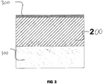
- Figure 3 shows a cross section of a ceramic coating formed on a metal substrate (100).
- the ceramic coating consists of a hard functional layer (200) and a thin (less than 14% of the total coating thickness) external porous layer (300).
- the surface of the ceramic coating has low roughness (Ra 0.6 to 2.1 ⁇ m).
- the invention is clarified by examples of the implementation of the process.
- the specimens to be coated were in the form of a disc 40mm in diameter and 6mm thick.
- the specimens were degreased before oxidation. After oxidation, the specimens were washed in de-ionised water and dried at 100°C for 20 minutes.
- the electrical parameters of the process were registered by an oscilloscope.
- the quality parameters of the coating were measured from transverse micro-sections.
- a specimen of aluminium alloy 2014 was oxidised for 35 minutes in phosphate-silicate electrolyte, pH 11, at temperature 40°C. Bipolar alternating electrical pulses of frequency 2500Hz were supplied to the bath. The current density was 35A/dm 2 , and the final voltage (amplitude) was: anode 900V, cathode 400V. Acoustic vibrations were generated in the bath by an aerohydrodynamic generator. The pressure of the electrolyte at the input into the generator was 4.5 bars. A dense coating of a dark grey colour, overall thickness 130 ⁇ 3 ⁇ m, including an external porous layer 14 ⁇ m thick, was obtained. The roughness of the oxide-coated surface was Ra 2.1 ⁇ m, its microhardness was 1900HV, and the porosity of the hard functional layer (not the external porous layer) was 4%.
- a specimen of magnesium alloy AZ91 was oxidised for two minutes in a phosphate-aluminate electrolyte to which 2g/l of ultra-disperse Al 2 O 3 powder with particle size 0.2 ⁇ m was added.
- the temperature of the electrolyte was 25°C, pH 12.5.
- Bipolar alternating electrical pulses of frequency 10,000Hz were supplied to the bath in turn.
- the current density was 10A/dm 2 and the final voltage (amplitude) was: anode 520V, cathode 240V.
- Acoustic vibrations were generated in the bath using an aerohydrodynamic generator.
- the pressure of the electrolyte at the input to the generator was 4.8 bars.
- the coating obtained was dense, of a white colour, overall thickness 20 ⁇ 1 ⁇ m, including an external porous layer of thickness 2 ⁇ m.
- the roughness of the oxidised surface was Ra 0.8 ⁇ m
- the microhardness of the coating was 600HV
- the porosity of the functional layer was 6%.
- a specimen of titanium alloy Ti Al6 V4 was oxidised for seven minutes in a phosphate-borate electrolyte to which 2g/l of ultra-disperse Al 2 O 3 with particle size 0.2 ⁇ m was added.
- the temperature of the electrolyte was 20°C, pH 9.
- Bipolar alternating electrical pulses of frequency 1,000Hz were supplied to the bath.
- the current density was 60A/dm 2 and the final voltage (amplitude) was: anode 500V, cathode 180V.
- Acoustic vibrations were generated in the bath using an aerohydrodynamic generator.
- the pressure of the electrolyte at the input to the generator was 4.0 bars.
- the coating obtained was dense, of a bluish-grey colour, overall thickness 15 ⁇ 1 ⁇ m, including an external porous layer of thickness 2 ⁇ m.
- the roughness of the oxidised surface was Ra 0.7 ⁇ m
- the microhardness of the coating was 750HV
- the porosity of the functional layer was 2%.
- the coating obtained was dense, of a light grey colour, overall thickness 65 ⁇ 2 ⁇ m, including an external porous layer of thickness 8 ⁇ m.
- the roughness of the oxidised surface was Ra 1.2 ⁇ m
- the microhardness of the coating was 900HV
- the porosity of the functional layer was 5%.
- the coating obtained was dense, of a dark grey colour, overall thickness 25 ⁇ 1 ⁇ m, including an external porous layer of thickness 2.5 ⁇ m.
- the roughness of the oxidised surface was Ra 1.0 ⁇ m
- the microhardness of the coating was 850HV
- the porosity of the functional layer was 5%.
- Bipolar electrical pulses one positive and two negative
- the current density was 50A/dm 2 and the final voltage (amplitude) was: anode 630V, cathode 260V.
- Acoustic vibrations were generated in the bath using an aerohydrodynamic generator.
- the pressure of the electrolyte at the input to the generator was 6.8 bars.
- the coating obtained was dense, white in colour, overall thickness 30 ⁇ 1 ⁇ m, including an external porous layer of thickness 3 ⁇ m.
- the roughness of the oxidised surface was Ra 0.9 ⁇ m
- the microhardness of the coating was 700HV
- the porosity of the functional layer was 3%.
- Table 1 also includes data from a known process of oxidising with industrial-frequency currents.
Landscapes
- Chemical & Material Sciences (AREA)
- Engineering & Computer Science (AREA)
- Chemical Kinetics & Catalysis (AREA)
- Electrochemistry (AREA)
- Materials Engineering (AREA)
- Metallurgy (AREA)
- Organic Chemistry (AREA)
- Crystallography & Structural Chemistry (AREA)
- Other Surface Treatments For Metallic Materials (AREA)
- Electroplating Methods And Accessories (AREA)
Claims (16)
- Procédé permettant la formation d'un revêtement en céramique (200, 300) sur un article (4) constitué de métal ou d'alliage (100) dans un bain électrolytique (1) équipé d'une première électrode et rempli d'un électrolyte alcalin aqueux (3), dans lequel est immergé l'article (100), connecté à une autre électrode, un courant à impulsion étant appliqué entre les électrodes de façon à pouvoir mener le procédé dans un régime d'oxydation électrolytique à décharge de plasma, le procédé comprenant les étapes de :i) alimentation des électrodes avec des impulsions de courant bipolaires hautes-fréquences à une fréquence de succession d'impulsions régulée ou à des fréquences supérieures ou égales à 500 Hz ; etii) application de vibrations acoustiques à l'électrolyte (3) de façon à générer un champ acoustique couvrant une gamme de fréquences audibles prédéterminées, la gamme de fréquences du champ acoustique comprenant la fréquence de succession d'impulsions régulée ou les fréquences d'impulsions de courant.
- Procédé selon la revendication 1, ledit revêtement (200, 300) étant formé sur les métaux Mg, Al, Ti, Nb, Ta, Zr, Hf et les alliages de ceux-ci, et aussi sur les composés et composites Al-Be, Ti-Al, Ni-Ti, Ni-Al, Ti-Nb, Al-Zr, Al-Al2O3, Mg-Al2O3.
- Procédé selon la revendication 1 ou 2, chaque impulsion de courant possédant une forme comprenant une forte augmentation initiale du courant jusqu'à un maximum en un temps qui n'excède pas 10 % de la durée totale de l'impulsion, suivie par une baisse d'abord rapide et ensuite plus progressive du courant jusqu'à 50 % de son maximum ou moins.
- Procédé selon l'une quelconque des revendications précédentes, lesdites vibrations acoustiques entraînant une saturation aéro-hydrodynamique de l'électrolyte (3) en oxygène.
- Procédé selon la revendication 4, ledit électrolyte (3) étant fourni avec de l'oxygène ou de l'air.
- Procédé selon l'une quelconque des revendications précédentes, comprenant en outre l'étape d'introduction de particules solides d'ultra-dispersion dans l'électrolyte (3) et de création d'un hydrosol stable au moyen des vibrations acoustiques.
- Procédé selon la revendication 6, lesdites particules solides possédant une taille qui est inférieure ou égale à 0,5 µm.
- Procédé selon la revendication 6 ou 7, lesdites particules solides comprenant des composés sous forme d'oxydes, borures, carbures, nitrures, siliciures et sulfures de métaux.
- Procédé selon l'une quelconque des revendications précédentes, ledit revêtement en céramique (200, 300) se formant à une vitesse allant de 2 à 10 µm/min.
- Procédé selon l'une quelconque des revendications précédentes, ledit courant appliqué à l'article (4) possédant une densité de courant allant de 3 à 200 A/dm2.
- Procédé selon la revendication 10, ledit courant appliqué à l'article (4) possédant une densité de courant allant de 10 à 60 A/dm2.
- Procédé selon l'une quelconque des revendications précédentes, ladite fréquence de succession d'impulsions étant comprise dans la gamme allant de 1 000 à 10 000 Hz.
- Appareil permettant la formation d'un revêtement en céramique (200, 300) sur un article (4) constitué de métal ou d'alliage (100) au moyen d'un régime d'oxydation électrolytique à décharge de plasma, l'appareil comprenant un bain électrolytique (1) avec électrodes, une source d'alimentation (12) pour l'envoi du courant à impulsion aux électrodes, et au moins un générateur de vibrations acoustiques (7), dans lequel :i) la source d'alimentation (12) est conçue pour alimenter les électrodes avec des impulsions de courant bipolaires hautes-fréquences à une fréquence de succession d'impulsions régulée ou des fréquences supérieures ou égales à 500 Hz ; etii) le au moins un générateur de vibrations acoustiques (7) est adapté pour l'application de vibrations acoustiques à l'électrolyte (3) lorsque celui-ci est contenu dans le bain (1), de façon à générer un champ acoustique couvrant une gamme de fréquences audibles prédéterminées, la gamme de fréquences du champ acoustique comprenant la fréquence de succession d'impulsions régulée ou les fréquences des impulsions de courant.
- Appareil selon la revendication 13, la source d'alimentation (12) étant conçue de sorte que chaque impulsion de courant possède une forme comprenant une forte augmentation initiale de courant jusqu'à un maximum en un temps qui n'excède pas 10 % de la durée totale de l'impulsion, suivie par une baisse d'abord rapide et ensuite plus progressive du courant jusqu'à 50 % de son maximum ou moins.
- Appareil selon la revendication 13 ou 14, ledit au moins un générateur acoustique (7) étant un résonateur aéro-hydrodynamique possédant au moins une entrée pour un écoulement de l'électrolyte (3).
- Appareil selon la revendication 15, lesdites vibrations acoustiques générées par le au moins un résonateur aéro-hydrodynamique (7) étant contrôlées par modification de la pression de l'écoulement de l'électrolyte à l'entrée du résonateur aéro-hydrodynamique (7).
Applications Claiming Priority (5)
| Application Number | Priority Date | Filing Date | Title |
|---|---|---|---|
| US123010 | 1993-09-17 | ||
| GB0207193A GB2386907B (en) | 2002-03-27 | 2002-03-27 | Process and device for forming ceramic coatings on metals and alloys, and coatings produced by this process |
| GB0207193 | 2002-03-27 | ||
| US10/123,010 US6896785B2 (en) | 2002-03-27 | 2002-04-15 | Process and device for forming ceramic coatings on metals and alloys, and coatings produced by this process |
| PCT/GB2002/004305 WO2003083181A2 (fr) | 2002-03-27 | 2002-09-23 | Procede et dispositif permettant de former des revetements en ceramique sur des metaux et des alliages, et revetements produits selon ledit procede |
Publications (2)
| Publication Number | Publication Date |
|---|---|
| EP1488024A2 EP1488024A2 (fr) | 2004-12-22 |
| EP1488024B1 true EP1488024B1 (fr) | 2017-05-03 |
Family
ID=28676486
Family Applications (1)
| Application Number | Title | Priority Date | Filing Date |
|---|---|---|---|
| EP02765036.5A Expired - Lifetime EP1488024B1 (fr) | 2002-03-27 | 2002-09-23 | Procede et dispositif permettant de former des revetements en ceramique sur des metaux et des alliages |
Country Status (6)
| Country | Link |
|---|---|
| EP (1) | EP1488024B1 (fr) |
| JP (2) | JP4182002B2 (fr) |
| CN (1) | CN100503899C (fr) |
| AU (1) | AU2002329410A1 (fr) |
| NO (1) | NO20034936L (fr) |
| WO (1) | WO2003083181A2 (fr) |
Cited By (2)
| Publication number | Priority date | Publication date | Assignee | Title |
|---|---|---|---|---|
| KR20200144792A (ko) | 2019-06-19 | 2020-12-30 | 오엠피주식회사 | 금속제 물품의 내표면에 산화피막을 형성하는 방법 |
| KR20200144789A (ko) | 2019-06-19 | 2020-12-30 | 오엠피주식회사 | 금속제 물품의 내표면에 산화피막을 형성하는 장치 |
Families Citing this family (53)
| Publication number | Priority date | Publication date | Assignee | Title |
|---|---|---|---|---|
| JP4182002B2 (ja) * | 2002-03-27 | 2008-11-19 | アイル・コート・リミテッド | 金属および合金にセラミック被膜を形成するプロセスと装置、およびこのプロセスによって生成される被膜 |
| US7196459B2 (en) * | 2003-12-05 | 2007-03-27 | International Resistive Co. Of Texas, L.P. | Light emitting assembly with heat dissipating support |
| CN100348780C (zh) * | 2004-03-16 | 2007-11-14 | 天津大学 | 脉冲镀镍基纳米复合镀层的方法及设备 |
| GB2422249A (en) * | 2005-01-15 | 2006-07-19 | Robert John Morse | Power substrate |
| CN100420775C (zh) * | 2005-05-23 | 2008-09-24 | 狄士春 | 钢铁表面微弧氧化处理方法 |
| CN100396823C (zh) * | 2005-09-29 | 2008-06-25 | 陕西科技大学 | 一种超声水热电沉积制备涂层或薄膜的方法及其装置 |
| CN100469946C (zh) * | 2005-12-19 | 2009-03-18 | 广东工业大学 | 一种TiC陶瓷涂层的制备方法 |
| JP4125765B2 (ja) * | 2006-09-28 | 2008-07-30 | 日本パーカライジング株式会社 | 金属のセラミックス皮膜コーティング方法およびそれに用いる電解液ならびにセラミックス皮膜および金属材料 |
| EP2084310A1 (fr) * | 2006-10-05 | 2009-08-05 | Boston Scientific Limited | Revêtements exempts de polymère pour dispositifs médicaux formés par dépôt électrolytique de plasma |
| JP5254811B2 (ja) | 2007-02-15 | 2013-08-07 | 環境エンジニアリング株式会社 | 導体微粒子を製造する方法 |
| EP1967615A1 (fr) * | 2007-03-07 | 2008-09-10 | Siemens Aktiengesellschaft | Procédé destiné à l'application d'une couche d'isolation thermique et pièce de turbine dotée d'une couche d'isolation thermique |
| EA012825B1 (ru) * | 2007-04-02 | 2009-12-30 | Владимир Никандрович Кокарев | Способ формирования на поверхности металлических изделий защитного керамического покрытия |
| JP2010533563A (ja) | 2007-07-19 | 2010-10-28 | ボストン サイエンティフィック リミテッド | 吸着抑制表面を有する内部人工器官 |
| JP2010535541A (ja) | 2007-08-03 | 2010-11-25 | ボストン サイエンティフィック リミテッド | 広い表面積を有する医療器具用のコーティング |
| GB0720982D0 (en) * | 2007-10-25 | 2007-12-05 | Plasma Coatings Ltd | Method of forming a bioactive coating |
| EP2271380B1 (fr) | 2008-04-22 | 2013-03-20 | Boston Scientific Scimed, Inc. | Dispositifs médicaux revêtus d une substance inorganique |
| WO2009132176A2 (fr) | 2008-04-24 | 2009-10-29 | Boston Scientific Scimed, Inc. | Dispositifs médicaux comportant des couches de particules inorganiques |
| CN101333673B (zh) * | 2008-07-29 | 2011-11-23 | 浙江工业大学 | 用于微弧氧化制备纳米陶瓷涂层的电解液及处理方法 |
| JP5394021B2 (ja) * | 2008-08-06 | 2014-01-22 | アイシン精機株式会社 | アルミニウム合金ピストン部材およびその製造方法 |
| EP2179752B1 (fr) * | 2008-10-06 | 2014-08-13 | Biotronik VI Patent AG | Implant et son procédé de fabrication |
| AT506583B9 (de) * | 2008-10-23 | 2009-12-15 | Happy Plating Gmbh | Elektrochemisches beschichtungsverfahren |
| DE102008043970A1 (de) * | 2008-11-21 | 2010-05-27 | Biotronik Vi Patent Ag | Verfahren zur Herstellung einer korrosionshemmenden Beschichtung auf einem Implantat aus einer biokorrodierbaren Magnesiumlegierung sowie nach dem Verfahren hergestelltes Implantat |
| DE102009012945A1 (de) * | 2009-03-12 | 2010-09-16 | Mtu Aero Engines Gmbh | Verfahren zur Herstellung einer abrasiven Beschichtung und Bauteil für eine Turbomaschine |
| GB2469115B (en) | 2009-04-03 | 2013-08-21 | Keronite Internat Ltd | Process for the enhanced corrosion protection of valve metals |
| CN101892507B (zh) * | 2010-07-29 | 2012-02-22 | 南昌航空大学 | 一种提高钛合金微弧氧化膜生长速度的方法 |
| ES2699495T3 (es) | 2011-02-08 | 2019-02-11 | Cambridge Nanotherm Ltd | Sustrato de metal aislado |
| KR101349076B1 (ko) * | 2011-07-20 | 2014-01-14 | 현대자동차주식회사 | 연료전지 스택용 매니폴드 블록의 산화층 형성 장치 및 방법 |
| WO2014078258A1 (fr) * | 2012-11-16 | 2014-05-22 | Merck Sharp & Dohme Corp. | Procédé de préparation d'agglomérats au moyen de la technologie de mélange acoustique |
| KR101476235B1 (ko) * | 2012-12-11 | 2014-12-24 | 한국기계연구원 | 플라즈마 전해산화를 이용한 마그네슘재 표면처리 방법, 이에 의해 형성된 마그네슘 양극산화피막 및 플라즈마 전해산화에 사용되는 마그네슘재 표면처리액 |
| KR101572849B1 (ko) * | 2013-04-23 | 2015-12-01 | 인제대학교 산학협력단 | 전기 화학 증착에 의한 나노 구조체의 제조 방법 및 이에 의하여 제조된 나노 구조체 |
| WO2014175653A1 (fr) * | 2013-04-23 | 2014-10-30 | 인제대학교 산학협력단 | Procédé de préparation de nanostructure par dépôt électrochimique, et nanostructure ainsi préparée |
| GB2513575B (en) | 2013-04-29 | 2017-05-31 | Keronite Int Ltd | Corrosion and erosion-resistant mixed oxide coatings for the protection of chemical and plasma process chamber components |
| KR101419273B1 (ko) * | 2013-08-27 | 2014-07-15 | (주)엠에스티테크놀로지 | 플라즈마 전해 산화에 의해 금속 표면에 투명층을 형성하는 방법 |
| CN103567405A (zh) * | 2013-11-04 | 2014-02-12 | 虞雪君 | 一种用于冶金连铸机结晶器的复合镀层材料 |
| CN103567404A (zh) * | 2013-11-04 | 2014-02-12 | 虞雪君 | 一种用于结晶器的复合镀层材料及制备方法 |
| CH708829A1 (fr) | 2013-11-11 | 2015-05-15 | Panerai Ag Off | Composant en alliage aluminium-lithium comprenant un revêtement céramique et procédé pour former le revêtement. |
| CN103695985B (zh) * | 2013-12-16 | 2016-02-10 | 电子科技大学 | 一种镍氢电池镍电极表面制备氧化钛涂层的方法 |
| CN104562130B (zh) * | 2014-08-22 | 2017-06-16 | 东莞市武华新材料有限公司 | 轻金属或其合金表面氧化钛基陶瓷膜层的制造方法 |
| US9506161B2 (en) * | 2014-12-12 | 2016-11-29 | Metal Industries Research & Development Centre | Surface treatment of a magnesium alloy |
| JP2016156036A (ja) * | 2015-02-23 | 2016-09-01 | 株式会社栗本鐵工所 | 皮膜形成方法 |
| KR101701268B1 (ko) * | 2015-04-09 | 2017-02-13 | 현대성우메탈 주식회사 | 마그네슘 합금용 플라즈마 전해 산화용 전해액 및 이를 이용한 전해산화방법 |
| CN108368632B (zh) * | 2015-12-16 | 2020-09-25 | 汉高股份有限及两合公司 | 用于在铝上沉积钛基保护涂层的方法 |
| CN109385654A (zh) * | 2017-08-11 | 2019-02-26 | 昆山汉鼎精密金属有限公司 | 自动微弧氧化系统及其方法 |
| CN110257878B (zh) * | 2019-07-16 | 2021-06-08 | 广西大学 | 一种制备铝钛复合板微弧氧化膜的方法 |
| RU2736943C1 (ru) * | 2020-04-24 | 2020-11-23 | Акционерное общество «МАНЭЛ» | Способ нанесения покрытия на изделия из вентильного металла или его сплава |
| CN113943964A (zh) * | 2020-07-15 | 2022-01-18 | 中国科学院上海硅酸盐研究所 | 钛合金表面热控耐磨损涂层及其制备方法 |
| CN111945204A (zh) * | 2020-09-07 | 2020-11-17 | 北京杜尔考特科技有限公司 | 一种轻金属纳米陶瓷化生产装置 |
| CN112708917A (zh) * | 2020-12-23 | 2021-04-27 | 西安工业大学 | 一种钛合金涡轮叶片表面微弧氧化层的制备方法 |
| CN113774459A (zh) * | 2021-09-29 | 2021-12-10 | 上海交通大学 | 一种锆合金表面致密高耐蚀微弧氧化膜层的制备方法 |
| GB2613562A (en) | 2021-12-03 | 2023-06-14 | Keronite International Ltd | Use of chelating agents in plasma electrolytic oxidation processes |
| CH720539A1 (fr) | 2023-02-24 | 2024-08-30 | Officine Panerai Ag | Composant en alliage de titane comprenant un revêtement céramique à la surface et procédé d'obtention du composant |
| US20250109518A1 (en) | 2023-09-29 | 2025-04-03 | Metal Improvement Company, Llc | High density and adhesion coating process and coatings formed thereby |
| CN118685832B (zh) * | 2024-08-22 | 2026-01-02 | 南方科技大学嘉兴研究院 | 多孔材料抛光系统、抛光方法及金属粉末低温除氧方法 |
Citations (2)
| Publication number | Priority date | Publication date | Assignee | Title |
|---|---|---|---|---|
| US5385662A (en) * | 1991-11-27 | 1995-01-31 | Electro Chemical Engineering Gmbh | Method of producing oxide ceramic layers on barrier layer-forming metals and articles produced by the method |
| WO2001081658A1 (fr) * | 2000-04-26 | 2001-11-01 | Jacques Beauvir | Procede electrolytique d'oxydation pour l'obtention d'un revêtement ceramique a la surface d'un metal |
Family Cites Families (11)
| Publication number | Priority date | Publication date | Assignee | Title |
|---|---|---|---|---|
| DD151330A1 (de) * | 1980-06-03 | 1981-10-14 | Peter Kurze | Verfahren zur herstellung von diffusionsschichten in metallen |
| RU2077612C1 (ru) * | 1993-09-14 | 1997-04-20 | Мамаев Анатолий Иванович | Способ нанесения покрытия на вентильные металлы и их сплавы |
| IL109857A (en) * | 1994-06-01 | 1998-06-15 | Almag Al | Electrolytic process and apparatus for coating metals |
| DE19546826C1 (de) * | 1995-12-15 | 1997-04-03 | Fraunhofer Ges Forschung | Verfahren und Einrichtung zur Vorbehandlung von Substraten |
| SK121099A3 (en) * | 1997-03-11 | 2000-06-12 | Almag Al | Process and apparatus for coating metals |
| CA2315792A1 (fr) * | 1997-12-17 | 1999-06-24 | Isle Coat Limited | Procede permettant d'obtenir des revetements de protection durs sur des articles faits d'alliages d'aluminium |
| CN1081093C (zh) * | 1998-02-24 | 2002-03-20 | 北京航空航天大学 | 一种高能脉冲电沉积陶瓷涂层的方法 |
| CN1262344A (zh) * | 1999-02-04 | 2000-08-09 | 哈尔滨三利亚实业发展有限公司 | 等离子体增强电化学表面陶瓷化方法及其制得产品 |
| JP2002121699A (ja) * | 2000-05-25 | 2002-04-26 | Nippon Techno Kk | めっき浴の振動流動とパルス状めっき電流との組み合わせを用いた電気めっき方法 |
| CN2441817Y (zh) * | 2000-08-31 | 2001-08-08 | 湖南省郴州市山河电子设备有限公司 | 超声波电镀装置 |
| JP4182002B2 (ja) * | 2002-03-27 | 2008-11-19 | アイル・コート・リミテッド | 金属および合金にセラミック被膜を形成するプロセスと装置、およびこのプロセスによって生成される被膜 |
-
2002
- 2002-09-23 JP JP2003580609A patent/JP4182002B2/ja not_active Expired - Lifetime
- 2002-09-23 EP EP02765036.5A patent/EP1488024B1/fr not_active Expired - Lifetime
- 2002-09-23 AU AU2002329410A patent/AU2002329410A1/en not_active Abandoned
- 2002-09-23 WO PCT/GB2002/004305 patent/WO2003083181A2/fr not_active Ceased
- 2002-09-23 CN CNB028285212A patent/CN100503899C/zh not_active Expired - Fee Related
-
2003
- 2003-11-06 NO NO20034936A patent/NO20034936L/no not_active Application Discontinuation
-
2007
- 2007-09-20 JP JP2007243844A patent/JP4722102B2/ja not_active Expired - Lifetime
Patent Citations (2)
| Publication number | Priority date | Publication date | Assignee | Title |
|---|---|---|---|---|
| US5385662A (en) * | 1991-11-27 | 1995-01-31 | Electro Chemical Engineering Gmbh | Method of producing oxide ceramic layers on barrier layer-forming metals and articles produced by the method |
| WO2001081658A1 (fr) * | 2000-04-26 | 2001-11-01 | Jacques Beauvir | Procede electrolytique d'oxydation pour l'obtention d'un revêtement ceramique a la surface d'un metal |
Cited By (2)
| Publication number | Priority date | Publication date | Assignee | Title |
|---|---|---|---|---|
| KR20200144792A (ko) | 2019-06-19 | 2020-12-30 | 오엠피주식회사 | 금속제 물품의 내표면에 산화피막을 형성하는 방법 |
| KR20200144789A (ko) | 2019-06-19 | 2020-12-30 | 오엠피주식회사 | 금속제 물품의 내표면에 산화피막을 형성하는 장치 |
Also Published As
| Publication number | Publication date |
|---|---|
| NO20034936L (no) | 2004-01-09 |
| JP4182002B2 (ja) | 2008-11-19 |
| WO2003083181A3 (fr) | 2004-09-10 |
| HK1059804A1 (en) | 2004-07-16 |
| AU2002329410A1 (en) | 2003-10-13 |
| NO20034936D0 (no) | 2003-11-06 |
| CN1623013A (zh) | 2005-06-01 |
| JP2005521794A (ja) | 2005-07-21 |
| EP1488024A2 (fr) | 2004-12-22 |
| CN100503899C (zh) | 2009-06-24 |
| WO2003083181A2 (fr) | 2003-10-09 |
| JP4722102B2 (ja) | 2011-07-13 |
| JP2008038256A (ja) | 2008-02-21 |
| AU2002329410A8 (en) | 2003-10-13 |
Similar Documents
| Publication | Publication Date | Title |
|---|---|---|
| EP1488024B1 (fr) | Procede et dispositif permettant de former des revetements en ceramique sur des metaux et des alliages | |
| US6896785B2 (en) | Process and device for forming ceramic coatings on metals and alloys, and coatings produced by this process | |
| Wang et al. | Effect of discharge pulsating on microarc oxidation coatings formed on Ti6Al4V alloy | |
| Hussein et al. | Production of anti-corrosion coatings on light alloys (Al, Mg, Ti) by plasma-electrolytic oxidation (PEO) | |
| JP3342697B2 (ja) | 高電流密度を用いて高い被覆速度で粒子上に金属被覆する電気めっき方法 | |
| Jiang et al. | Micro-arc oxidation (MAO) to improve the corrosion resistance of magnesium (Mg) alloys | |
| WO2008120046A1 (fr) | Procédé de formation d'un revêtement protecteur en céramique sur la surface de produits métalliques | |
| EP2077343A1 (fr) | Matériau métallique à revêtement céramique et procédé pour le fabriquer | |
| CN109183115A (zh) | 一种表面覆有超硬微弧氧化陶瓷膜的铝合金的制备方法 | |
| JP2837397B2 (ja) | アルミニウムまたはアルミニウム合金の陽極酸化処理装置 | |
| Fattah‐alhosseini et al. | Enhancing plasma electrolytic oxidation (peo) coatings on magnesium alloys: the critical role of surface pretreatments | |
| CN108774742A (zh) | 一种控制铝合金微弧氧化陶瓷复合膜复合量的方法 | |
| CN113787196B (zh) | 一种高性能铝合金处理方法 | |
| CN115917052B (zh) | 在阀门金属及其合金制成的物品上施加涂层的方法 | |
| CN106947991A (zh) | 一种铝合金表面耐磨耐蚀抗热震涂层的制备方法 | |
| TWI571536B (zh) | 利用微弧氧化生成彩色氧化膜的方法 | |
| KR101191957B1 (ko) | 플라즈마전해 양극산화방법 | |
| Kalra et al. | Experimental study on developed electrochemical micro machining of hybrid MMC | |
| CN113755918B (zh) | 一种耐腐蚀铝合金 | |
| RU2851841C1 (ru) | Способ микродугового оксидирования трехмерных изделий | |
| WO2022084897A1 (fr) | Procédé de fabrication d'un revêtement céramique à la surface d'un substrat en alliage d'aluminium au moyen d'une oxydation par plasma électrolytique | |
| US20060207884A1 (en) | Method of producing corundum layer on metal parts | |
| RU2725516C1 (ru) | Способ электролитно-плазменной обработки детали | |
| RU2039133C1 (ru) | Способ анодирования алюминия и его сплавов | |
| CN115584544A (zh) | 一种微弧氧化方法及设备 |
Legal Events
| Date | Code | Title | Description |
|---|---|---|---|
| PUAI | Public reference made under article 153(3) epc to a published international application that has entered the european phase |
Free format text: ORIGINAL CODE: 0009012 |
|
| 17P | Request for examination filed |
Effective date: 20040818 |
|
| AK | Designated contracting states |
Kind code of ref document: A2 Designated state(s): AT BE BG CH CY CZ DE DK EE ES FI FR GB GR IE IT LI LU MC NL PT SE SK TR |
|
| AX | Request for extension of the european patent |
Extension state: AL LT LV MK RO SI |
|
| RIN1 | Information on inventor provided before grant (corrected) |
Inventor name: SAMSONOV, VICTOR IOSIFOVICH Inventor name: SHATROV, ALEXANDER SERGEEVICH |
|
| RIN1 | Information on inventor provided before grant (corrected) |
Inventor name: SAMSONOV, VICTOR IOSIFOVICH Inventor name: SHATROV, ALEXANDER SERGEEVICH |
|
| RAP1 | Party data changed (applicant data changed or rights of an application transferred) |
Owner name: KERONITE INTERNATIONAL LIMITED |
|
| 17Q | First examination report despatched |
Effective date: 20141014 |
|
| REG | Reference to a national code |
Ref country code: DE Ref legal event code: R079 Ref document number: 60248855 Country of ref document: DE Free format text: PREVIOUS MAIN CLASS: C25D0001000000 Ipc: C25D0005180000 |
|
| GRAP | Despatch of communication of intention to grant a patent |
Free format text: ORIGINAL CODE: EPIDOSNIGR1 |
|
| RIC1 | Information provided on ipc code assigned before grant |
Ipc: C25D 5/20 20060101ALI20161109BHEP Ipc: C25D 11/00 20060101ALI20161109BHEP Ipc: C25D 5/18 20060101AFI20161109BHEP Ipc: C25D 11/02 20060101ALI20161109BHEP |
|
| INTG | Intention to grant announced |
Effective date: 20161125 |
|
| GRAS | Grant fee paid |
Free format text: ORIGINAL CODE: EPIDOSNIGR3 |
|
| GRAA | (expected) grant |
Free format text: ORIGINAL CODE: 0009210 |
|
| AK | Designated contracting states |
Kind code of ref document: B1 Designated state(s): AT BE BG CH CY CZ DE DK EE ES FI FR GB GR IE IT LI LU MC NL PT SE SK TR |
|
| REG | Reference to a national code |
Ref country code: GB Ref legal event code: FG4D |
|
| REG | Reference to a national code |
Ref country code: AT Ref legal event code: REF Ref document number: 890094 Country of ref document: AT Kind code of ref document: T Effective date: 20170515 Ref country code: CH Ref legal event code: EP |
|
| REG | Reference to a national code |
Ref country code: IE Ref legal event code: FG4D |
|
| REG | Reference to a national code |
Ref country code: DE Ref legal event code: R096 Ref document number: 60248855 Country of ref document: DE |
|
| REG | Reference to a national code |
Ref country code: NL Ref legal event code: MP Effective date: 20170503 |
|
| REG | Reference to a national code |
Ref country code: AT Ref legal event code: MK05 Ref document number: 890094 Country of ref document: AT Kind code of ref document: T Effective date: 20170503 |
|
| PG25 | Lapsed in a contracting state [announced via postgrant information from national office to epo] |
Ref country code: FI Free format text: LAPSE BECAUSE OF FAILURE TO SUBMIT A TRANSLATION OF THE DESCRIPTION OR TO PAY THE FEE WITHIN THE PRESCRIBED TIME-LIMIT Effective date: 20170503 Ref country code: ES Free format text: LAPSE BECAUSE OF FAILURE TO SUBMIT A TRANSLATION OF THE DESCRIPTION OR TO PAY THE FEE WITHIN THE PRESCRIBED TIME-LIMIT Effective date: 20170503 Ref country code: GR Free format text: LAPSE BECAUSE OF FAILURE TO SUBMIT A TRANSLATION OF THE DESCRIPTION OR TO PAY THE FEE WITHIN THE PRESCRIBED TIME-LIMIT Effective date: 20170804 Ref country code: AT Free format text: LAPSE BECAUSE OF FAILURE TO SUBMIT A TRANSLATION OF THE DESCRIPTION OR TO PAY THE FEE WITHIN THE PRESCRIBED TIME-LIMIT Effective date: 20170503 |
|
| PG25 | Lapsed in a contracting state [announced via postgrant information from national office to epo] |
Ref country code: NL Free format text: LAPSE BECAUSE OF FAILURE TO SUBMIT A TRANSLATION OF THE DESCRIPTION OR TO PAY THE FEE WITHIN THE PRESCRIBED TIME-LIMIT Effective date: 20170503 Ref country code: BG Free format text: LAPSE BECAUSE OF FAILURE TO SUBMIT A TRANSLATION OF THE DESCRIPTION OR TO PAY THE FEE WITHIN THE PRESCRIBED TIME-LIMIT Effective date: 20170803 Ref country code: SE Free format text: LAPSE BECAUSE OF FAILURE TO SUBMIT A TRANSLATION OF THE DESCRIPTION OR TO PAY THE FEE WITHIN THE PRESCRIBED TIME-LIMIT Effective date: 20170503 |
|
| PG25 | Lapsed in a contracting state [announced via postgrant information from national office to epo] |
Ref country code: CZ Free format text: LAPSE BECAUSE OF FAILURE TO SUBMIT A TRANSLATION OF THE DESCRIPTION OR TO PAY THE FEE WITHIN THE PRESCRIBED TIME-LIMIT Effective date: 20170503 Ref country code: DK Free format text: LAPSE BECAUSE OF FAILURE TO SUBMIT A TRANSLATION OF THE DESCRIPTION OR TO PAY THE FEE WITHIN THE PRESCRIBED TIME-LIMIT Effective date: 20170503 Ref country code: EE Free format text: LAPSE BECAUSE OF FAILURE TO SUBMIT A TRANSLATION OF THE DESCRIPTION OR TO PAY THE FEE WITHIN THE PRESCRIBED TIME-LIMIT Effective date: 20170503 Ref country code: SK Free format text: LAPSE BECAUSE OF FAILURE TO SUBMIT A TRANSLATION OF THE DESCRIPTION OR TO PAY THE FEE WITHIN THE PRESCRIBED TIME-LIMIT Effective date: 20170503 |
|
| REG | Reference to a national code |
Ref country code: DE Ref legal event code: R097 Ref document number: 60248855 Country of ref document: DE |
|
| PG25 | Lapsed in a contracting state [announced via postgrant information from national office to epo] |
Ref country code: IT Free format text: LAPSE BECAUSE OF FAILURE TO SUBMIT A TRANSLATION OF THE DESCRIPTION OR TO PAY THE FEE WITHIN THE PRESCRIBED TIME-LIMIT Effective date: 20170503 |
|
| PLBE | No opposition filed within time limit |
Free format text: ORIGINAL CODE: 0009261 |
|
| STAA | Information on the status of an ep patent application or granted ep patent |
Free format text: STATUS: NO OPPOSITION FILED WITHIN TIME LIMIT |
|
| 26N | No opposition filed |
Effective date: 20180206 |
|
| REG | Reference to a national code |
Ref country code: CH Ref legal event code: PL |
|
| GBPC | Gb: european patent ceased through non-payment of renewal fee |
Effective date: 20170923 |
|
| PG25 | Lapsed in a contracting state [announced via postgrant information from national office to epo] |
Ref country code: MC Free format text: LAPSE BECAUSE OF FAILURE TO SUBMIT A TRANSLATION OF THE DESCRIPTION OR TO PAY THE FEE WITHIN THE PRESCRIBED TIME-LIMIT Effective date: 20170503 |
|
| REG | Reference to a national code |
Ref country code: IE Ref legal event code: MM4A |
|
| REG | Reference to a national code |
Ref country code: BE Ref legal event code: MM Effective date: 20170930 |
|
| PG25 | Lapsed in a contracting state [announced via postgrant information from national office to epo] |
Ref country code: LU Free format text: LAPSE BECAUSE OF NON-PAYMENT OF DUE FEES Effective date: 20170923 |
|
| REG | Reference to a national code |
Ref country code: FR Ref legal event code: ST Effective date: 20180531 |
|
| PG25 | Lapsed in a contracting state [announced via postgrant information from national office to epo] |
Ref country code: GB Free format text: LAPSE BECAUSE OF NON-PAYMENT OF DUE FEES Effective date: 20170923 Ref country code: IE Free format text: LAPSE BECAUSE OF NON-PAYMENT OF DUE FEES Effective date: 20170923 Ref country code: LI Free format text: LAPSE BECAUSE OF NON-PAYMENT OF DUE FEES Effective date: 20170930 Ref country code: CH Free format text: LAPSE BECAUSE OF NON-PAYMENT OF DUE FEES Effective date: 20170930 |
|
| PG25 | Lapsed in a contracting state [announced via postgrant information from national office to epo] |
Ref country code: FR Free format text: LAPSE BECAUSE OF NON-PAYMENT OF DUE FEES Effective date: 20171002 Ref country code: BE Free format text: LAPSE BECAUSE OF NON-PAYMENT OF DUE FEES Effective date: 20170930 |
|
| PG25 | Lapsed in a contracting state [announced via postgrant information from national office to epo] |
Ref country code: CY Free format text: LAPSE BECAUSE OF NON-PAYMENT OF DUE FEES Effective date: 20170503 |
|
| PG25 | Lapsed in a contracting state [announced via postgrant information from national office to epo] |
Ref country code: TR Free format text: LAPSE BECAUSE OF FAILURE TO SUBMIT A TRANSLATION OF THE DESCRIPTION OR TO PAY THE FEE WITHIN THE PRESCRIBED TIME-LIMIT Effective date: 20170503 |
|
| PG25 | Lapsed in a contracting state [announced via postgrant information from national office to epo] |
Ref country code: PT Free format text: LAPSE BECAUSE OF FAILURE TO SUBMIT A TRANSLATION OF THE DESCRIPTION OR TO PAY THE FEE WITHIN THE PRESCRIBED TIME-LIMIT Effective date: 20170503 |
|
| PGFP | Annual fee paid to national office [announced via postgrant information from national office to epo] |
Ref country code: DE Payment date: 20210924 Year of fee payment: 20 |
|
| REG | Reference to a national code |
Ref country code: DE Ref legal event code: R071 Ref document number: 60248855 Country of ref document: DE |