EP1488975A1 - Dämpfungsvorrichtung für hydraulisches Aggregat - Google Patents
Dämpfungsvorrichtung für hydraulisches Aggregat Download PDFInfo
- Publication number
- EP1488975A1 EP1488975A1 EP04102197A EP04102197A EP1488975A1 EP 1488975 A1 EP1488975 A1 EP 1488975A1 EP 04102197 A EP04102197 A EP 04102197A EP 04102197 A EP04102197 A EP 04102197A EP 1488975 A1 EP1488975 A1 EP 1488975A1
- Authority
- EP
- European Patent Office
- Prior art keywords
- elastic element
- hydraulic unit
- damping
- vibrations
- elastic
- Prior art date
- Legal status (The legal status is an assumption and is not a legal conclusion. Google has not performed a legal analysis and makes no representation as to the accuracy of the status listed.)
- Granted
Links
- 238000013016 damping Methods 0.000 title claims abstract description 22
- 229920001971 elastomer Polymers 0.000 claims description 3
- 239000000463 material Substances 0.000 claims description 2
- 239000002184 metal Substances 0.000 description 8
- 238000010521 absorption reaction Methods 0.000 description 3
- 230000005540 biological transmission Effects 0.000 description 2
- 238000011161 development Methods 0.000 description 1
- 230000018109 developmental process Effects 0.000 description 1
- 239000000806 elastomer Substances 0.000 description 1
- 210000003734 kidney Anatomy 0.000 description 1
Images

Classifications
-
- F—MECHANICAL ENGINEERING; LIGHTING; HEATING; WEAPONS; BLASTING
- F04—POSITIVE - DISPLACEMENT MACHINES FOR LIQUIDS; PUMPS FOR LIQUIDS OR ELASTIC FLUIDS
- F04B—POSITIVE-DISPLACEMENT MACHINES FOR LIQUIDS; PUMPS
- F04B53/00—Component parts, details or accessories not provided for in, or of interest apart from, groups F04B1/00 - F04B23/00 or F04B39/00 - F04B47/00
- F04B53/001—Noise damping
- F04B53/003—Noise damping by damping supports
-
- B—PERFORMING OPERATIONS; TRANSPORTING
- B60—VEHICLES IN GENERAL
- B60T—VEHICLE BRAKE CONTROL SYSTEMS OR PARTS THEREOF; BRAKE CONTROL SYSTEMS OR PARTS THEREOF, IN GENERAL; ARRANGEMENT OF BRAKING ELEMENTS ON VEHICLES IN GENERAL; PORTABLE DEVICES FOR PREVENTING UNWANTED MOVEMENT OF VEHICLES; VEHICLE MODIFICATIONS TO FACILITATE COOLING OF BRAKES
- B60T8/00—Arrangements for adjusting wheel-braking force to meet varying vehicular or ground-surface conditions, e.g. limiting or varying distribution of braking force
- B60T8/32—Arrangements for adjusting wheel-braking force to meet varying vehicular or ground-surface conditions, e.g. limiting or varying distribution of braking force responsive to a speed condition, e.g. acceleration or deceleration
- B60T8/34—Arrangements for adjusting wheel-braking force to meet varying vehicular or ground-surface conditions, e.g. limiting or varying distribution of braking force responsive to a speed condition, e.g. acceleration or deceleration having a fluid pressure regulator responsive to a speed condition
- B60T8/36—Arrangements for adjusting wheel-braking force to meet varying vehicular or ground-surface conditions, e.g. limiting or varying distribution of braking force responsive to a speed condition, e.g. acceleration or deceleration having a fluid pressure regulator responsive to a speed condition including a pilot valve responding to an electromagnetic force
- B60T8/3615—Electromagnetic valves specially adapted for anti-lock brake and traction control systems
- B60T8/3675—Electromagnetic valves specially adapted for anti-lock brake and traction control systems integrated in modulator units
- B60T8/368—Electromagnetic valves specially adapted for anti-lock brake and traction control systems integrated in modulator units combined with other mechanical components, e.g. pump units, master cylinders
- B60T8/3685—Electromagnetic valves specially adapted for anti-lock brake and traction control systems integrated in modulator units combined with other mechanical components, e.g. pump units, master cylinders characterised by the mounting of the modulator unit onto the vehicle
-
- F—MECHANICAL ENGINEERING; LIGHTING; HEATING; WEAPONS; BLASTING
- F04—POSITIVE - DISPLACEMENT MACHINES FOR LIQUIDS; PUMPS FOR LIQUIDS OR ELASTIC FLUIDS
- F04B—POSITIVE-DISPLACEMENT MACHINES FOR LIQUIDS; PUMPS
- F04B39/00—Component parts, details, or accessories, of pumps or pumping systems specially adapted for elastic fluids, not otherwise provided for in, or of interest apart from, groups F04B25/00 - F04B37/00
- F04B39/0027—Pulsation and noise damping means
- F04B39/0044—Pulsation and noise damping means with vibration damping supports
-
- F—MECHANICAL ENGINEERING; LIGHTING; HEATING; WEAPONS; BLASTING
- F04—POSITIVE - DISPLACEMENT MACHINES FOR LIQUIDS; PUMPS FOR LIQUIDS OR ELASTIC FLUIDS
- F04B—POSITIVE-DISPLACEMENT MACHINES FOR LIQUIDS; PUMPS
- F04B53/00—Component parts, details or accessories not provided for in, or of interest apart from, groups F04B1/00 - F04B23/00 or F04B39/00 - F04B47/00
- F04B53/16—Casings; Cylinders; Cylinder liners or heads; Fluid connections
-
- F—MECHANICAL ENGINEERING; LIGHTING; HEATING; WEAPONS; BLASTING
- F16—ENGINEERING ELEMENTS AND UNITS; GENERAL MEASURES FOR PRODUCING AND MAINTAINING EFFECTIVE FUNCTIONING OF MACHINES OR INSTALLATIONS; THERMAL INSULATION IN GENERAL
- F16L—PIPES; JOINTS OR FITTINGS FOR PIPES; SUPPORTS FOR PIPES, CABLES OR PROTECTIVE TUBING; MEANS FOR THERMAL INSULATION IN GENERAL
- F16L55/00—Devices or appurtenances for use in, or in connection with, pipes or pipe systems
- F16L55/02—Energy absorbers; Noise absorbers
- F16L55/033—Noise absorbers
- F16L55/035—Noise absorbers in the form of specially adapted hangers or supports
Definitions
- the present invention relates to a device for Damping vibrations for a hydraulic unit.
- Hydraulic units are used in motor vehicles for example in braking systems, stability systems or Traction systems used.
- the hydraulic units are in usually compact components, which a pump, a electrical actuator, valves, etc. include.
- Vibrations and structure-borne noise which, for example, over a bracket with which the hydraulic unit on Vehicle is attached to other components of the vehicle is transmitted.
- a structure-borne noise which however other vehicle components is transmitted turns out to be Noise, both inside and outside the vehicle noticeable.
- the structure-borne noise can also be heard on the Hydraulic unit existing connections and lines be transmitted. Because in today's vehicles Noise requirements always become larger, in particular a transfer of the Structure-borne noise in the vehicle interior can be prevented to avoid a negative impression among users of the Vehicle.
- the inventive device for damping Vibrations for a hydraulic unit with the Features of claim 1, however, has the Advantage that by means of an elastic element Damping vibrations of the hydraulic unit, in particular damping structure-borne noise becomes.
- the elastic element is on one Pipe connection element of the hydraulic unit arranged.
- a bracket for attaching the hydraulic unit on the vehicle is on attached elastic element.
- the elastic elements By arranging the elastic elements on the Line connection elements can be the least possible Space required for the elastic elements become.
- the elastic elements take over at the same time vibration damping for the hydraulic Line connections and lines etc. as well as for that entire hydraulic unit because the bracket on the elastic elements is arranged.
- a separate elastic element is arranged at each line connection.
- a common elastic element provided, which dampens vibrations at every line connection. This is a small number of components is necessary. Furthermore can thereby the best possible damping of the vibrations can be achieved, since the vibrations also over the common elastic element can cancel each other.
- the elastic Element preferably surrounded by an inelastic band.
- the inelastic band is, for example, made of metal or Made of plastic.
- the elastic Element preferably a circumferential, groove-shaped recess to take up the inelastic tape.
- elastic Element In order to influence the damping behavior of the To provide elastic element are elastic Element preferably provided openings.
- the openings can be used as through openings or as blind holes be trained. Depending on the size of the individual openings or the number of openings or the distances between the openings can have different damping behavior can be achieved. It is also conceivable to use inelastic components such as. Insert cylindrical pins into the openings to to get different vibration damping behavior.
- an additional damping element arranged between the bracket and a housing of the hydraulic unit an additional damping element arranged.
- the elastic element is particularly preferably made of one Elastomer and in particular made of a rubber material manufactured.
- the elastic elements Furthermore preferably enclose the elastic elements the pipe connections completely.
- the elastic elements the Line connections only partially, e.g. three quarters, enclose.
- the fastener can e.g. a mother attached to the inelastic band be one which is passed through the holder Can accommodate bolts.
- the device for damping according to the invention especially for hydraulic units in vehicles for Anti-lock braking systems (ABS), anti-slip regulations (ASR) and / or electronic stability systems (ESP) are used.
- ABS Anti-lock braking systems
- ASR anti-slip regulations
- ESP electronic stability systems
- FIGS. 1 and 2 a first embodiment of the present invention described.
- the hydraulic unit comprises an electric motor 2 as a drive and a housing 3, in which the other components of the hydraulic unit, such as. a pump and valves are arranged.
- the housing From the Housing protrude two connecting pieces 5, to which each a line 4 in the form of a tube or Hose can be arranged.
- the lines 4 are for example by means of union screws or nuts 6 on Connection piece 5 attached.
- each line connection elastic element 7 There is one around each line connection elastic element 7 arranged.
- the elastic elements 7 have a Essentially oval in shape and surround the Connection piece 5 of the hydraulic unit 1 Completely.
- the elastic elements 7 a central recess 8 and a first edge 9 and a second edge 10, wherein the middle recess 8 between the two edges 9, 10 is arranged.
- the middle recess 8 is used for Inclusion of a metal band, which wraps around the elastic element 7 is arranged.
- a bracket 11 is attached to the surrounding metal band.
- the bracket 11 serves to fasten the entire hydraulic unit 1 on other body components of the vehicle. So is the hydraulic unit 1 via the elastic elements 7 and the bracket 11 attached to the vehicle. For reasons the bracket in FIG 2 not shown.
- vibrations such as structure-borne noise
- these vibrations are caused by the on the Line connections arranged elastic elements 7th steamed and absorbed. This prevents the Vibrations or structure-borne noise via the brackets 11 on the vehicle or on the lines to others Components of the vehicle, especially in the Vehicle interior, are transferred.
- the elastic elements 7 there are several for mounting the elastic elements 7 Possibilities.
- the elastic elements 7 before attaching the lines 4 to the line connections be plugged in and then the lines 4 be attached.
- Another mounting option is available in that the elastic elements 7 with a slot be provided so that they are also in the assembled state of the Line 4 are pulled over the line connections can.
- the metal band can also be in advance elastic element 7 or a slot have and subsequently on the elastic element 7 be attached. This can be done, for example, using a Screw connection to be carried out around the two ends of the metal strip to connect to each other.
- the elastic member 7 can also be designed such that it covers the entire Connection piece 5 covered and also the Connection nut 6 for fastening line 4 covered. It would also be conceivable that part of the line 4 is covered by the elastic element 7.
- the geometry of the elastic elements is such designed that in the main direction of movement (in Figure 1 marked by the double arrow A) of the hydraulic unit 1 generated vibrations, a superimposed stress and shear stress occurs. This can be done, for example, by providing free spaces in the elastic element 7 realized in a relatively simple manner become.
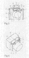
- FIGS. 3 and 4 a hydraulic unit 1 according to a second Embodiment of the present invention described.
- the elastic element 7 has two openings 12, which the connecting pieces of the hydraulic unit 1 take up.
- the elastic element 7 essentially has has a kidney shape and is for easier attachment of the Bracket 11 also provided with a metal band 13, which is arranged all around the elastic element 7 is.
- the metal strip 13 is by means of a bolt 18 on elastic element 7 attached.
- the elastic element 7 is fastened to the housing 3 by means of bolts 14.
- the bolts 14 are hollow and have an internal thread 15, on which a line (not shown) can be attached.
- bracket 11 To attach the bracket 11 are on the circumferential Metal strap 13 fasteners 16 with internal thread, e.g. Nuts, attached. In these fasteners 16th are bolts 17 which are guided through the brackets 11 are screwed in. The hydraulic unit is thus 1 via the elastic element 7 and the brackets 11 on the Vehicle attached.
- fasteners 16th In these fasteners 16th are bolts 17 which are guided through the brackets 11 are screwed in.
- the hydraulic unit is thus 1 via the elastic element 7 and the brackets 11 on the Vehicle attached.
- the Damping device provided very inexpensively can be and takes up a very small amount of space.
Landscapes
- Engineering & Computer Science (AREA)
- Mechanical Engineering (AREA)
- General Engineering & Computer Science (AREA)
- Physics & Mathematics (AREA)
- Electromagnetism (AREA)
- Fluid Mechanics (AREA)
- Transportation (AREA)
- Valves And Accessory Devices For Braking Systems (AREA)
- Vibration Prevention Devices (AREA)
- Arrangement Or Mounting Of Propulsion Units For Vehicles (AREA)
- Regulating Braking Force (AREA)
Abstract
Description
- Figur 1
- eine schematische Draufansicht eines hydraulischen Aggregats gemäß einem ersten Ausführungsbeispiel der vorliegenden Erfindung,
- Figur 2
- eine schematische Seitenansicht des in Figur 1 gezeigten hydraulischen Aggregats,
- Figur 3
- eine schematische, perspektivische Explosionsdarstellung eines hydraulischen Aggregats gemäß einem zweiten Ausführungsbeispiel der vorliegenden Erfindung, und
- Figur 4
- eine schematische, perspektivische Ansicht des in Figur 3 gezeigten hydraulischen Aggregats im zusammengebauten Zustand.
Claims (11)
- Vorrichtung zur Dämpfung von Schwingungen für ein hydraulisches Aggregat (1), umfassend ein elastisches Element (7), wobei das elastische Element (7) an einem Leitungsanschlusselement (4, 5, 6) des hydraulischen Aggregats angeordnet ist und wobei das elastische Element (7) mit einer Halterung (11) zur Befestigung des hydraulischen Aggregats verbunden ist.
- Vorrichtung nach Anspruch 1, dadurch gekennzeichnet, dass an jedem Leitungsanschlusselement (4, 5, 6) ein separates elastisches Element (7) angeordnet ist.
- Vorrichtung nach Anspruch 1, gekennzeichnet durch ein gemeinsames elastisches Element (7) für alle Leitungsanschlusselemente (4, 5, 6) des hydraulischen Aggregats.
- Vorrichtung nach einem der vorhergehenden Ansprüche, dadurch gekennzeichnet, dass das elastische Element (7) von einem unelastischen Band (13) umgeben ist.
- Vorrichtung nach Anspruch 4, dadurch gekennzeichnet, dass das elastische Element (7) eine umlaufende Ausnehmung (8) zur Aufnahme des unelastischen Bandes (13) aufweist.
- Vorrichtung nach einem der vorhergehenden Ansprüche, dadurch gekennzeichnet, dass das elastische Element (7) Öffnungen zur gezielten Beeinflussung des Dämpfungsverhaltens des elastischen Elements (7) aufweist.
- Vorrichtung nach einem der vorhergehenden Ansprüche, dadurch gekennzeichnet, dass zwischen der Halterung (11) und dem Gehäuse des hydraulischen Aggregats (1) ein zusätzliches Dämpfungselement angeordnet ist.
- Vorrichtung nach einem der vorhergehenden Ansprüche, dadurch gekennzeichnet, dass das elastische Element aus einem Gummimaterial hergestellt ist.
- Vorrichtung nach einem der vorhergehenden Ansprüche, dadurch gekennzeichnet, dass das elastische Element (7) die Leitungsanschlüsse (4, 5, 6) vollständig umschließt.
- Vorrichtung nach einem der vorhergehenden Ansprüche, dadurch gekennzeichnet, dass am unelastischen Band (13) Befestigungselemente (16) zur Befestigung der Halterung (11) angeordnet sind.
- Verwendung einer Vorrichtung zur Dämpfung von Schwingungen eines hydraulischen Aggregats (1) in einem Antiblockiersystem und/oder einer Antischlupfregelung und/oder einem elektronischen Stabilitätssystem für Fahrzeuge.
Applications Claiming Priority (2)
| Application Number | Priority Date | Filing Date | Title |
|---|---|---|---|
| DE2003126913 DE10326913B4 (de) | 2003-06-16 | 2003-06-16 | Dämpfungsvorrichtung für hydraulisches Aggregat |
| DE10326913 | 2003-06-16 |
Publications (2)
| Publication Number | Publication Date |
|---|---|
| EP1488975A1 true EP1488975A1 (de) | 2004-12-22 |
| EP1488975B1 EP1488975B1 (de) | 2007-08-15 |
Family
ID=33394828
Family Applications (1)
| Application Number | Title | Priority Date | Filing Date |
|---|---|---|---|
| EP20040102197 Expired - Lifetime EP1488975B1 (de) | 2003-06-16 | 2004-05-18 | Hydraulisches Aggregat |
Country Status (2)
| Country | Link |
|---|---|
| EP (1) | EP1488975B1 (de) |
| DE (1) | DE10326913B4 (de) |
Cited By (1)
| Publication number | Priority date | Publication date | Assignee | Title |
|---|---|---|---|---|
| CN111577672A (zh) * | 2020-05-29 | 2020-08-25 | 湖南理工职业技术学院 | 一种风机降噪减震装置 |
Citations (6)
| Publication number | Priority date | Publication date | Assignee | Title |
|---|---|---|---|---|
| DE3025601A1 (de) * | 1980-07-05 | 1982-01-21 | Daimler-Benz Ag, 7000 Stuttgart | Anordnung zum geraeuscharmen aufhaengen von langgestreckten bauteilen, wie rohren oder schlaeuchen |
| US4569637A (en) * | 1984-02-22 | 1986-02-11 | Walbro Corporation | In-tank fuel pump assembly |
| JPH0733005A (ja) * | 1993-07-14 | 1995-02-03 | Toyota Motor Corp | ブレーキ装置用アクチュエータユニット |
| EP0890778A1 (de) * | 1997-07-11 | 1999-01-13 | Hutchinson | Geschlitzte Hülse aus Kautschuk oder ähnlichem Material zum Verbinden einer Befestigungslasche an ein starres Rohr |
| US6216734B1 (en) * | 1999-02-18 | 2001-04-17 | Denso Corporation | Rotary device support structure for fuel supply apparatus |
| US20020190572A1 (en) * | 2001-06-13 | 2002-12-19 | Unisia Jecs Corporation | Support structure and method for supporting a hydraulic unit of a brake system on a vehicle body, and hydraulic unit arrangement for a vehicle brake system |
Family Cites Families (1)
| Publication number | Priority date | Publication date | Assignee | Title |
|---|---|---|---|---|
| DE19930635A1 (de) * | 1999-07-02 | 2001-01-04 | Mannesmann Rexroth Ag | Einrichtung zur Umwandlung von elektrischer in hydraulische Energie |
-
2003
- 2003-06-16 DE DE2003126913 patent/DE10326913B4/de not_active Expired - Fee Related
-
2004
- 2004-05-18 EP EP20040102197 patent/EP1488975B1/de not_active Expired - Lifetime
Patent Citations (6)
| Publication number | Priority date | Publication date | Assignee | Title |
|---|---|---|---|---|
| DE3025601A1 (de) * | 1980-07-05 | 1982-01-21 | Daimler-Benz Ag, 7000 Stuttgart | Anordnung zum geraeuscharmen aufhaengen von langgestreckten bauteilen, wie rohren oder schlaeuchen |
| US4569637A (en) * | 1984-02-22 | 1986-02-11 | Walbro Corporation | In-tank fuel pump assembly |
| JPH0733005A (ja) * | 1993-07-14 | 1995-02-03 | Toyota Motor Corp | ブレーキ装置用アクチュエータユニット |
| EP0890778A1 (de) * | 1997-07-11 | 1999-01-13 | Hutchinson | Geschlitzte Hülse aus Kautschuk oder ähnlichem Material zum Verbinden einer Befestigungslasche an ein starres Rohr |
| US6216734B1 (en) * | 1999-02-18 | 2001-04-17 | Denso Corporation | Rotary device support structure for fuel supply apparatus |
| US20020190572A1 (en) * | 2001-06-13 | 2002-12-19 | Unisia Jecs Corporation | Support structure and method for supporting a hydraulic unit of a brake system on a vehicle body, and hydraulic unit arrangement for a vehicle brake system |
Non-Patent Citations (1)
| Title |
|---|
| PATENT ABSTRACTS OF JAPAN vol. 1995, no. 05 30 June 1995 (1995-06-30) * |
Cited By (1)
| Publication number | Priority date | Publication date | Assignee | Title |
|---|---|---|---|---|
| CN111577672A (zh) * | 2020-05-29 | 2020-08-25 | 湖南理工职业技术学院 | 一种风机降噪减震装置 |
Also Published As
| Publication number | Publication date |
|---|---|
| DE10326913A1 (de) | 2005-01-20 |
| EP1488975B1 (de) | 2007-08-15 |
| DE10326913B4 (de) | 2005-06-23 |
Similar Documents
| Publication | Publication Date | Title |
|---|---|---|
| EP1307667B1 (de) | Vorrichtung zur elastischen lagerung eines hydraulischen aggregats einer fahrzeugbremsanlage in einem fahrzeug | |
| DE4334924C2 (de) | Befestigungsvorrichtung für eine vibrationsverhindernde Schraubenfeder | |
| DE69806454T2 (de) | System zur verminderung von vibrationen in kraftfahrzeugen | |
| EP1152156A1 (de) | Vorrichtung zur insbesondere akustisch entkoppelten Befestigung | |
| DE102009029569A1 (de) | Vorrichtung zur schwingungsdämpfenden Lagerung eines Fluidaggregats und zugehöriges Fluidaggregat | |
| WO2010034477A1 (de) | Brems- sowie zusatzgeräteanordnung einer pneumatischen bremsanlage eines fahrzeuges | |
| DE202016107350U1 (de) | Gedämpfte Befestigungselementanordnung | |
| EP1597491B1 (de) | Bremssattel | |
| WO2007118558A1 (de) | Halterung für ein motor-pumpen-aggregat, insbesondere für eine servolenkung | |
| DE102010047160A1 (de) | Anordnung zur Befestigung einer Vibrationseinheit an einem Lenkrad | |
| DE102008045461A1 (de) | Akustische Seitenabdeckung für einen Motor | |
| WO2005095815A1 (de) | Bremsvorrichtung | |
| DE10326913B4 (de) | Dämpfungsvorrichtung für hydraulisches Aggregat | |
| DE10349702B4 (de) | Schwingungsdämpfende Aggregathaltevorrichtung | |
| DE19915591C2 (de) | Vorrichtung zur Übertragung von Körperschall | |
| DE102018204151A1 (de) | Lenkanordnung eines Fahrzeugs | |
| EP2008886A2 (de) | Befestigungsklammer | |
| DE602006000829T2 (de) | Schwingungsdämpfende Vorrichtung und Struktur mit dieser | |
| DE102018128430A1 (de) | Befestigung eines Zündlenkschlosses an einem Zusatzhalter | |
| DE60300535T2 (de) | Brennkraftmaschine mit einer Pumpe sowie Verfahren zum Austauschen der Pumpe | |
| DE102011079617A1 (de) | Schraubverbindung | |
| DE60009401T2 (de) | Vorrichtung zum Befestigen eines Hitzeschildes für eine Ölpumpe | |
| WO2005039946A1 (de) | Hydraulikaggregat mit integrierter sensorvorrichtung | |
| DE102017105368B4 (de) | Kompressorgehäuse für einen Klimakompressor eines Fahrzeugs | |
| DE10007056A1 (de) | Befestigungsanordnung für eine Scheibenwischeranlage einer Fahrzeugkarosserie |
Legal Events
| Date | Code | Title | Description |
|---|---|---|---|
| PUAI | Public reference made under article 153(3) epc to a published international application that has entered the european phase |
Free format text: ORIGINAL CODE: 0009012 |
|
| AK | Designated contracting states |
Kind code of ref document: A1 Designated state(s): AT BE BG CH CY CZ DE DK EE ES FI FR GB GR HU IE IT LI LU MC NL PL PT RO SE SI SK TR |
|
| AX | Request for extension of the european patent |
Extension state: AL HR LT LV MK |
|
| 17P | Request for examination filed |
Effective date: 20050622 |
|
| AKX | Designation fees paid |
Designated state(s): CH DE FR GB IT LI |
|
| GRAP | Despatch of communication of intention to grant a patent |
Free format text: ORIGINAL CODE: EPIDOSNIGR1 |
|
| RTI1 | Title (correction) |
Free format text: HYDRAULIC UNIT |
|
| RBV | Designated contracting states (corrected) |
Designated state(s): CH FR GB IT LI |
|
| REG | Reference to a national code |
Ref country code: DE Ref legal event code: 8566 |
|
| GRAS | Grant fee paid |
Free format text: ORIGINAL CODE: EPIDOSNIGR3 |
|
| GRAA | (expected) grant |
Free format text: ORIGINAL CODE: 0009210 |
|
| AK | Designated contracting states |
Kind code of ref document: B1 Designated state(s): CH FR GB IT LI |
|
| REG | Reference to a national code |
Ref country code: GB Ref legal event code: FG4D Free format text: NOT ENGLISH |
|
| REG | Reference to a national code |
Ref country code: CH Ref legal event code: EP |
|
| GBT | Gb: translation of ep patent filed (gb section 77(6)(a)/1977) |
Effective date: 20071128 |
|
| ET | Fr: translation filed | ||
| PLBE | No opposition filed within time limit |
Free format text: ORIGINAL CODE: 0009261 |
|
| STAA | Information on the status of an ep patent application or granted ep patent |
Free format text: STATUS: NO OPPOSITION FILED WITHIN TIME LIMIT |
|
| 26N | No opposition filed |
Effective date: 20080516 |
|
| REG | Reference to a national code |
Ref country code: CH Ref legal event code: PL |
|
| PG25 | Lapsed in a contracting state [announced via postgrant information from national office to epo] |
Ref country code: LI Free format text: LAPSE BECAUSE OF NON-PAYMENT OF DUE FEES Effective date: 20080531 Ref country code: CH Free format text: LAPSE BECAUSE OF NON-PAYMENT OF DUE FEES Effective date: 20080531 |
|
| PGFP | Annual fee paid to national office [announced via postgrant information from national office to epo] |
Ref country code: GB Payment date: 20100324 Year of fee payment: 7 |
|
| PGFP | Annual fee paid to national office [announced via postgrant information from national office to epo] |
Ref country code: FR Payment date: 20100608 Year of fee payment: 7 |
|
| PGFP | Annual fee paid to national office [announced via postgrant information from national office to epo] |
Ref country code: IT Payment date: 20100526 Year of fee payment: 7 |
|
| GBPC | Gb: european patent ceased through non-payment of renewal fee |
Effective date: 20110518 |
|
| REG | Reference to a national code |
Ref country code: FR Ref legal event code: ST Effective date: 20120131 |
|
| PG25 | Lapsed in a contracting state [announced via postgrant information from national office to epo] |
Ref country code: IT Free format text: LAPSE BECAUSE OF NON-PAYMENT OF DUE FEES Effective date: 20110518 |
|
| PG25 | Lapsed in a contracting state [announced via postgrant information from national office to epo] |
Ref country code: FR Free format text: LAPSE BECAUSE OF NON-PAYMENT OF DUE FEES Effective date: 20110531 |
|
| PG25 | Lapsed in a contracting state [announced via postgrant information from national office to epo] |
Ref country code: GB Free format text: LAPSE BECAUSE OF NON-PAYMENT OF DUE FEES Effective date: 20110518 |