EP1489005B1 - Machine à cercler avec dispositif d'alimentation et de tensionnement de la bande avec recharge automatique - Google Patents
Machine à cercler avec dispositif d'alimentation et de tensionnement de la bande avec recharge automatique Download PDFInfo
- Publication number
- EP1489005B1 EP1489005B1 EP04012162.6A EP04012162A EP1489005B1 EP 1489005 B1 EP1489005 B1 EP 1489005B1 EP 04012162 A EP04012162 A EP 04012162A EP 1489005 B1 EP1489005 B1 EP 1489005B1
- Authority
- EP
- European Patent Office
- Prior art keywords
- strap
- feed
- wheels
- tensioning
- wheel
- Prior art date
- Legal status (The legal status is an assumption and is not a legal conclusion. Google has not performed a legal analysis and makes no representation as to the accuracy of the status listed.)
- Expired - Lifetime
Links
- 230000002441 reversible effect Effects 0.000 claims description 11
- 230000008901 benefit Effects 0.000 description 6
- 230000004048 modification Effects 0.000 description 2
- 238000012986 modification Methods 0.000 description 2
- 230000000712 assembly Effects 0.000 description 1
- 238000000429 assembly Methods 0.000 description 1
- 238000010438 heat treatment Methods 0.000 description 1
- 230000007246 mechanism Effects 0.000 description 1
- 230000037361 pathway Effects 0.000 description 1
- 238000011144 upstream manufacturing Methods 0.000 description 1
Images

Classifications
-
- B—PERFORMING OPERATIONS; TRANSPORTING
- B65—CONVEYING; PACKING; STORING; HANDLING THIN OR FILAMENTARY MATERIAL
- B65B—MACHINES, APPARATUS OR DEVICES FOR, OR METHODS OF, PACKAGING ARTICLES OR MATERIALS; UNPACKING
- B65B13/00—Bundling articles
- B65B13/18—Details of, or auxiliary devices used in, bundling machines or bundling tools
-
- B—PERFORMING OPERATIONS; TRANSPORTING
- B65—CONVEYING; PACKING; STORING; HANDLING THIN OR FILAMENTARY MATERIAL
- B65B—MACHINES, APPARATUS OR DEVICES FOR, OR METHODS OF, PACKAGING ARTICLES OR MATERIALS; UNPACKING
- B65B13/00—Bundling articles
- B65B13/02—Applying and securing binding material around articles or groups of articles, e.g. using strings, wires, strips, bands or tapes
- B65B13/04—Applying and securing binding material around articles or groups of articles, e.g. using strings, wires, strips, bands or tapes with means for guiding the binding material around the articles prior to severing from supply
-
- B—PERFORMING OPERATIONS; TRANSPORTING
- B65—CONVEYING; PACKING; STORING; HANDLING THIN OR FILAMENTARY MATERIAL
- B65B—MACHINES, APPARATUS OR DEVICES FOR, OR METHODS OF, PACKAGING ARTICLES OR MATERIALS; UNPACKING
- B65B2210/00—Specific aspects of the packaging machine
- B65B2210/12—Means for automatically detecting and removing jammed straps in strapping machines, e.g. jam clearing devices
Definitions
- the present invention is directed to a strapping machine feed system. More particularly, the present invention is directed to a strapping machine feed system in which strap is refed following a strap error or fault.
- Strapping machines are well known in the art for securing straps around loads.
- One type of known strapper is a stationary unit that includes a strapping head or weld head and drive mechanism mounted within a frame.
- a chute is mounted to the frame, through which the strapping material is fed.
- a table-top or work surface is likewise mounted to the frame.
- a feed system for such an arrangement is known from EP 0 231 458 A2 .
- Said feed system comprises a band feeding roller with a first pressing roller and upstream of this a band returning roller with a second pressing roller.
- the chute is mounted from about the work surface, and the strapping head is mounted below the work surface. Strap is fed from a source or dispenser to the strapping or weld head.
- the strapping head provides a number of functions. First, it includes a plurality of grippers for gripping portions of the strap during the course of a strapping operation. The strapping head also includes a cutter to cut the strap from a strap source or supply. Last, the strapping head includes a sealer to seal an overlying course of strapping material onto itself. This seal is commonly referred to as a weld and is effected by heating overlying courses of the strap by use of a vibrating element or a heated element.
- Strapping material is fed from the dispenser into the strapping head first via a pair of infeed wheels and second via a feed assembly.
- the infeed wheels are typically located immediately inside of the strapping machine (e.g., inside of an enclosure or cabinet).
- the infeed wheels facilitate smoothly feeding the strapping material into the strapper and supplying strapping material into the slack box.
- the slack box is an area between the infeed wheels and the strapping head that is used to store a length of "slack" strapping material for use by the strapping head and is also an area for storing take-up strap that has been rewound or tensioned around the load.
- the feed assembly includes a pair of tensioning wheels and a pair of feed wheels.
- the tensioning wheels are locate downstream of the infeed wheels, and a guide extends between the tensioning and feed wheels.
- the slack box is disposed about the guide area, between the infeed and tensioning wheels.
- the feed wheels are located between the tensioning wheels and the strapping head.
- the feed wheels feed the strap material into the strapping head (and around the strap chute).
- a guide is disposed between the tensioning wheels and the feed wheels to provide a pathway for the strap as it is fed into the strapping head by the feed wheels and as it is pulled from the strapping head (and from around the chute) by the tensioning wheels.
- a strapping machine having a strap feeding and tensioning system with automatic refeed.
- a system automatically detects a strap error or fault, stops strap retraction or take-up and refeeds the strap into the strapping head following that error or fault. More desirably, such a system refeeds the strap into the strapping head without additional parts or assemblies beyond those employed for feeding and tensioning the strap material during normal machine operations.
- a feed system for a strapping machine automatically detects a strap error or fault, stops strap retraction or take-up and refeeds the strap into the strapping head following that error or fault.
- Such a system is configured for use in a strapping machine of the type having a strap supply, a strap chute and a strapping head disposed between the strap supply and the chute.
- a feed wheel drive is operably connected to one of the feed wheels and a tensioning wheel drive is operably connected to one of the tensioning wheels.
- the feed and tensioning wheel drives are reversible motors.
- the other of the feed and tensioning wheels are idler or pinch wheels.
- a sensor is disposed along the strap path for generating a signal to indicate a movement or a lack of movement of the strap material along the strap path.
- the strap material is conveyed around the strap chute by forward rotation of the feed wheels and is retracted around the load by reverse rotation of the feed wheels.
- the strap is tensioned around the load by forward rotation of the tensioning wheels. Forward rotation of the tensioning wheels commences upon receipt of the lack of movement of strap material signal following retracting the strap material.
- the machine When, following reverse rotation of the feed wheels for retracting the strap material, the machine is in a faulted strap condition (by the sensor failing to generate a lack of movement signal), the feed wheels stop rotation, and the tensioning wheels rotate in a reverse direction to convey the strap material into the nip between the feed wheels.
- the senor is disposed proximal the idler feed wheel to sense the movement and lack of movement of the idler feed wheel.
- the movement and lack of movement of the idler feed wheel correspond to the movement and lack of movement of the strap material signals, respectively.
- the tensioning wheels are moved into and out of engagement with one another by a linkage that is operably connected to the pinch tensioning wheel for moving an axis of rotation of the pinch tensioning wheel toward and away from the driven tensioning wheel.
- the pinch tensioning wheel is mounted to an eccentric shaft that is operably connected to the linkage.
- a strapping machine having a feed system that automatically detects a strap error or fault, stops strap retraction or take-up and refeeds the strap into the strapping head following that error or fault is also disclosed.
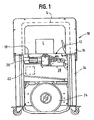
- FIG. 1 is a front view of an exemplary strapping machine having a strap path access guide embodying the principles of the present invention
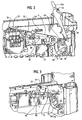
- FIG. 3 is a perspective illustration similar to FIG. 2 showing the access guide in the closed or operating position
- FIG. 4 is a perspective illustration of the rear of the strapping machine.
- FIG. 1 there is shown a strapping machine 10 having a feed system with automatic refeed 12 embodying the principles of the present invention.
- the strapping machine 10 includes, generally, a frame 14, a strap chute 16 and a table top or work surface 18.
- the feed assembly 12 and a strapping head 20 are mounted below the work surface 18.
- a controller 22 provides automatic operation and control of the strapper 10.
- the strapping head 20 receives strapping material S from a dispenser 24.
- the strap S is fed or pulled from the dispenser 24 by infeed wheels 26.
- the infeed wheels 26 are mounted immediately inside of and within the machine 10. Strap S is conveyed from the infeed wheels 26 to the feed assembly 12 (past a slack box 28).
- the slack box 28 is used as a "storage" region for strap S that has been fed into the machine 10 but has not yet been pulled into the strapping head 20, and for strap S that has been taken-up from around the load L, as during the take-up or tensioning cycles.
- the feed assembly 12 includes two pairs of wheels, namely a pair of feed wheels 30, 32 and a pair of tensioning wheels 34, 36.
- One of the feed wheels 30 is driven and the other is an idler or pinch wheel 32.
- one of the tensioning wheels 34 is driven and the other is an idler or pinch wheel 36.
- the feed wheels 30, 32 are located proximal the strapping head 20, and the tensioning wheels 34, 36 are located proximal the slack box 28 and infeed wheels 26.
- a lower guide 38 extends between infeed wheels 26 and the tensioning wheels 34, 36.
- An upper guide 40 extends between the tensioning wheels 34, 36 and the feed wheels 30, 32, a portion of which guide 40 also extends beyond the feed wheels 30, 32 to the strapping head 20.
- the driven feed and tensioning wheels 30, 34 are fixed relative to the frame 14.
- the idler (or pinch) feed wheel 32 is biasedly mounted to the guide 40. During the strapping cycle, the idler feed wheel 32 is maintained in contact with the driven feed wheel 30.
- a stall sensor 46 is located proximal the idler wheel 32 to monitor (and provide a signal) upon indication that the idler wheel 32 has stalled or stopped rotating.
- the pinch tensioning wheel 36 is mounted to an eccentric shaft 48 that is in turn operably connected, by a linkage 50, to a cam 52 in the strapping head 20.
- This cammed arrangement is configured to bring the pinch tensioning wheel 36 into contact with (i.e., to engage) the driven wheel 34 and to separate (i.e., disengage) the wheels 34, 36 from one another. In this manner, the pinch wheel 36 is moved into and out of engagement with the driven tensioning wheel 34 to drive or "idle" the strap S.
- the first portion is the feed portion of the strapping cycle, during which strap S is "pulled" by the feed wheels 30, 32, conveyed though the strapping head 20, around the strap chute 16 and back to the strapping head 22.
- the cycle then progresses to the take-up portion of the cycle which is when the strap S is released from the chute 16 and is taken-up at high speed until it contacts or lies on the load L.
- the machine 10 progresses into the tensioning portion of the strapping cycle, during which the strap S is tensioned or pulled tight around the load L.
- the feed wheels 30, 32 rotate in a "forward" direction (as seen in FIG. 2 , the driven wheel 30 rotates counter-clockwise), with the idler wheel 32 rotating by virtue of the movement of strap S between the driven 30 and idler 32 wheels.
- the tensioning wheels 34, 36 are separated (or open) from one another (by the strapping head cam 52-linkage 50-eccentric shaft 48 arrangement) to permit the feed wheels 30, 32 to "pull" the strap S.
- the strap chute 16 opens to allow the strap S to be pulled to the load L.
- the feed wheels 30, 32 reverse (the tensioning wheels 34, 36 are still separated or open) and the strap S is pulled from the chute 16 on to the load L.
- Take-up is carried out at a high speed but at a low force.
- the strap S will "stall".
- the stall sensor 46 By virtue of the dependence of rotation of the feed idler wheel 32 on the movement of the strap S, when the strap S "stalls", so does the idler wheel 32. This stall is sensed by the stall sensor 46.
- the machine 10 Upon sensing a stall in the idler wheel 32, the machine 10 progresses to the tensioning portion of the strapping cycle. In this portion of the cycle, the strapping head 20 indexes (which moves the cam 52), which in turn moves the linkage 50 to bring the tensioning wheels 34, 36 into contact.
- the tensioning motor 44 then actuates (rotating in a forward direction) to tension the strap S around the load L. Upon reaching a predetermined tension, the tensioning motor 44 stops (stopping the tensioning wheels 34, 36) and the strap S is sealed and cut.
- the machine 10 then resets and recommences the strapping cycle (per the controller 22).
- the machine 10 in the course of the strapping cycle will progress to the take-up portion of the cycle.
- the stall sensor 46 fails to sense a stall within a predetermined period of time, for example, two seconds, the feed wheels 30, 32 stop the (reversed) take-up rotation and the machine 10 indexes to an "off-normal" refeed mode. In the refeed mode, the feed wheels 30, 32 are stopped and the tensioning wheels 34, 36 are engaged with one another (by operation of the strapping head cam 52-link 50-eccentric shaft 48 arrangement).
- the present feed system with automatic refeed 12 provides a number of advantages over known strapping machine systems.
- One such advantage is the ability to automatically refeed strap S to the strapping head 20 following a faulted strap condition.
- Those skilled in the art will readily recognize and appreciate the advantage that such as system provides to, among other things, enhance the operational efficiency and reduce the machine "down-time" that might otherwise occur.
Landscapes
- Engineering & Computer Science (AREA)
- Mechanical Engineering (AREA)
- Basic Packing Technique (AREA)
Claims (8)
- Système d'alimentation (12) conçu pour une machine de cerclage (10) du type ayant une alimentation en bande de cerclage (24, 28) et un canal de cerclage (16), la machine de cerclage (10) comportant une tête de cerclage (20) disposée entre l'alimentation en bande de cerclage (24, 28) et le canal (16), la machine de cerclage (10) étant configurée pour positionner, tendre et sceller un matériau de cerclage (S) autour d'une charge (L), le système d'alimentation (12) comprenant :un chemin de cerclage (P) allant de l'alimentation en bande de cerclage jusqu'à la tête de cerclage (20),une paire de roues de tensionnement (34, 36) disposées le long du chemin de cerclage (P) à proximité de l'alimentation en bande de cerclage ;une paire de roues d'alimentation (30, 32) disposées le long du chemin de cerclage (P) à proximité de la tête de cerclage (20), les roues d'alimentation (30, 32) définissant entre elles un pinçage ;un entraînement de roue d'alimentation (42) connecté fonctionnellement à l'une des roues d'alimentation (30) et un entraînement de roue de tensionnement (44) connecté fonctionnellement à l'une des roues de tensionnement (34) ;caractérisé parun capteur (46) disposé le long du chemin de cerclage (P) pour générer un signal indiquant un mouvement ou une absence de mouvement du matériau de cerclage (S) le long du chemin de cerclage (P),le système d'alimentation étant configuré de telle sorte que dans un cycle de cerclage, le matériau de cerclage (S) soit acheminé autour du canal de cerclage (16) par une rotation vers l'avant des roues d'alimentation (30, 32), soit rétracté autour de la charge par une rotation en sens inverse des roues d'alimentation (30, 32) et soit tendu autour de la charge par une rotation vers l'avant des roues de tensionnement (34, 36), une rotation vers l'avant des roues de tensionnement (34, 36) commençant à la réception du signal indiquant une absence de mouvement du matériau de cerclage suite à la rétraction du matériau de cerclage (S), et de telle sorte que suite à la rotation en sens inverse des roues d'alimentation (30, 32) pour rétracter le matériau de cerclage, dans le cas d'un état défectueux de la bande de cerclage, si le capteur (46) ne produit pas un signal indiquant une absence de mouvement du matériau de cerclage à l'intérieur d'une période de temps prédéterminée, les roues d'alimentation (30, 32) arrêtent de tourner, et les roues de tensionnement (34, 36) tournent dans le sens inverse afin de transporter le matériau de cerclage (S) jusque dans le pinçage entre les roues d'alimentation (30, 32).
- Système d'alimentation (12) selon la revendication 1, dans lequel la roue d'alimentation à laquelle est connecté fonctionnellement l'entraînement (42) est une roue d'alimentation entraînée (30) et l'autre roue d'alimentation est une roue d'alimentation folle (32) et dans lequel la roue de tensionnement à laquelle est connecté fonctionnellement l'entraînement (44) est une roue de tensionnement entraînée (34) et l'autre roue de tensionnement est une roue de tensionnement de pinçage (36).
- Système d'alimentation (12) selon la revendication 2, dans lequel le capteur (46) est disposé à proximité de la roue d'alimentation folle (32) en vue de détecter le mouvement et l'absence de mouvement de la roue d'alimentation folle (32), le mouvement et l'absence de mouvement de la roue d'alimentation folle (32) correspondant aux signaux indiquant le mouvement et l'absence de mouvement du matériau de cerclage, respectivement.
- Système d'alimentation (12) selon la revendication 3, dans lequel les roues de tensionnement (34, 36) peuvent être déplacées en engagement et hors d'engagement l'une avec l'autre, les roues de tensionnement (34, 36) pouvant être déplacées hors d'engagement l'une avec l'autre lorsque le matériau de cerclage (S) est acheminé autour du canal de cerclage et lorsque le matériau de cerclage (S) est rétracté autour de la charge, les roues de tensionnement (34, 36) étant déplacées en engagement l'une avec l'autre lorsque le matériau de cerclage est tendu autour de la charge (L) et lorsque la bande de cerclage (S) est réalimentée dans le pinçage de la roue d'alimentation suite à un état défectueux de la bande de cerclage.
- Système d'alimentation (12) selon la revendication 1, dans lequel l'une des roues de tensionnement est une roue de tensionnement entraînée (34) et l'autre roue de tensionnement est une roue de tensionnement de pinçage (36), et comportant un moyen (50) de déplacement des roues de tensionnement (34, 36) en et hors d'engagement l'une avec l'autre.
- Système d'alimentation (12) selon la revendication 5, dans lequel le moyen de déplacement est une liaison (50) connectée fonctionnellement à la roue de tensionnement de pinçage (36) pour déplacer un axe de rotation de la roue de tensionnement de pinçage vers la roue de tensionnement entraînée (34) et à l'écart de celle-ci.
- Système d'alimentation (12) selon la revendication 6, dans lequel la roue de tensionnement de pinçage (36) est montée sur un arbre excentrique (48) connecté fonctionnellement à la liaison (50).
- Système d'alimentation (12) selon la revendication 1, dans lequel l'entraînement de roue d'alimentation et l'entraînement de roue de tensionnement sont des moteurs réversibles (42, 44).
Applications Claiming Priority (2)
| Application Number | Priority Date | Filing Date | Title |
|---|---|---|---|
| US600198 | 2003-06-20 | ||
| US10/600,198 US6981353B2 (en) | 2003-06-20 | 2003-06-20 | Strapping machine with strap feeding and tensioning system with automatic refeed |
Publications (3)
| Publication Number | Publication Date |
|---|---|
| EP1489005A2 EP1489005A2 (fr) | 2004-12-22 |
| EP1489005A3 EP1489005A3 (fr) | 2012-02-22 |
| EP1489005B1 true EP1489005B1 (fr) | 2014-01-08 |
Family
ID=33418565
Family Applications (1)
| Application Number | Title | Priority Date | Filing Date |
|---|---|---|---|
| EP04012162.6A Expired - Lifetime EP1489005B1 (fr) | 2003-06-20 | 2004-05-22 | Machine à cercler avec dispositif d'alimentation et de tensionnement de la bande avec recharge automatique |
Country Status (3)
| Country | Link |
|---|---|
| US (1) | US6981353B2 (fr) |
| EP (1) | EP1489005B1 (fr) |
| ES (1) | ES2454191T3 (fr) |
Families Citing this family (11)
| Publication number | Priority date | Publication date | Assignee | Title |
|---|---|---|---|---|
| ITMI20031261A1 (it) * | 2003-06-20 | 2004-12-21 | Messersi Packaging Srl | Macchina reggiatrice con gruppo perfezionato di movimentazione della reggia. |
| USD547779S1 (en) * | 2005-04-15 | 2007-07-31 | Strapack Corporation | Strapping packing machine |
| CN201086841Y (zh) * | 2007-09-07 | 2008-07-16 | 杭州永创机械有限公司 | 捆扎机的打包带送带导引装置 |
| US8356641B2 (en) | 2007-11-02 | 2013-01-22 | Band-It-Idex, Inc. | Stationary band clamping apparatus |
| US10518914B2 (en) | 2008-04-23 | 2019-12-31 | Signode Industrial Group Llc | Strapping device |
| US11999516B2 (en) | 2008-04-23 | 2024-06-04 | Signode Industrial Group Llc | Strapping device |
| DE102011075629B4 (de) * | 2011-05-11 | 2016-09-15 | Smb Schwede Maschinenbau Gmbh | Verfahren zur Ansteuerung der Bandantriebseinrichtung einer Umreifungsmaschine sowie entsprechende Umreifungsmaschine |
| CN102530291B (zh) * | 2011-12-22 | 2013-07-10 | 杭州永创智能设备股份有限公司 | 一种新型打包机 |
| WO2014127550A1 (fr) * | 2013-02-21 | 2014-08-28 | 杭州永创智能设备股份有限公司 | Cœur de machine d'emballage |
| DE102014225880A1 (de) * | 2014-12-15 | 2016-06-16 | Krones Aktiengesellschaft | Umreifungskopf und Verfahren zum Umgang mit einem Umreifungsband |
| CH713646A2 (de) | 2017-01-30 | 2018-09-28 | Signode Ind Group Llc | Umreifungsvorrichtung mit einer Spanneinrichtung. |
Family Cites Families (20)
| Publication number | Priority date | Publication date | Assignee | Title |
|---|---|---|---|---|
| US3447447A (en) * | 1967-02-21 | 1969-06-03 | Stanley Works | Strapping mechanism |
| DE3300039A1 (de) * | 1982-01-08 | 1983-07-21 | Shoko Kiko Co., Ltd., Shijo nawate, Osaka | Verfahren zum regulieren der spannung eines umschnuerungsbandes in einer umschnuerungsmaschine |
| JPS6077820A (ja) * | 1983-10-03 | 1985-05-02 | ニチロ工業株式会社 | バンド式梱包機のバンド引戻し引締め装置 |
| US4724659A (en) * | 1985-12-24 | 1988-02-16 | Nichiro Kogyo Company Ltd. | Band type strapping machine |
| US4912912A (en) * | 1987-05-30 | 1990-04-03 | Strapack Corporation | Control apparatus in strapping machine |
| JPS6458614A (en) * | 1987-08-18 | 1989-03-06 | Nakano Eng Kk | Method and apparatus for band feed and backfeed on packing machine |
| JP2740804B2 (ja) * | 1990-02-09 | 1998-04-15 | ストラパック株式会社 | 梱包機における空梱包バンドの除去方法 |
| DE4014307C2 (de) * | 1990-05-04 | 1996-11-07 | Rmo Systempack Gmbh | Packmaschine |
| JPH0444921A (ja) * | 1990-06-11 | 1992-02-14 | Sutorapatsuku Kk | 梱包機におけるバンド供給装置 |
| DE4138800A1 (de) * | 1991-11-26 | 1993-05-27 | Signode Bernpak Gmbh | Verfahren und vorrichtung zur vermeidung von umreifungsmittelbedingten betriebsunterbrechungen an maschinen zum umreifen von packstuecken |
| JP2857280B2 (ja) * | 1992-06-10 | 1999-02-17 | ストラパック株式会社 | 梱包機におけるバンド供給・引締方法及び装置 |
| US5333438A (en) * | 1992-11-06 | 1994-08-02 | Signode Corporation | Dual coil power strapping machine |
| JPH07187119A (ja) * | 1993-12-28 | 1995-07-25 | Kioritz Corp | 梱包機 |
| DE19730449A1 (de) * | 1997-07-16 | 1999-01-21 | Mosca G Maschf | Spannvorrichtung für Umreifungsmaschinen |
| JPH11255206A (ja) * | 1998-03-10 | 1999-09-21 | Naigai Kk | 梱包機における進退バンド案内路構造 |
| US6173557B1 (en) * | 1998-12-03 | 2001-01-16 | Gin Dan Enterprises Corp. | Tape-leading mechanism for an automatic packer |
| DE29904910U1 (de) * | 1999-03-17 | 1999-06-10 | Tekpak Corp., Taichung | Führungsband-Verpackungsmaschine |
| US6568158B2 (en) * | 2000-07-31 | 2003-05-27 | Strapack Corporation | Band-applying apparatus and method for use in packing system |
| EP1249397B1 (fr) * | 2001-04-09 | 2005-01-19 | Nichiro Kogyo Co., Ltd. | Machine de cerclage avec arc de guidage du lien |
| JP3502856B2 (ja) * | 2001-07-06 | 2004-03-02 | 寛 畑谷 | テープによる結束機 |
-
2003
- 2003-06-20 US US10/600,198 patent/US6981353B2/en not_active Expired - Lifetime
-
2004
- 2004-05-22 EP EP04012162.6A patent/EP1489005B1/fr not_active Expired - Lifetime
- 2004-05-22 ES ES04012162.6T patent/ES2454191T3/es not_active Expired - Lifetime
Also Published As
| Publication number | Publication date |
|---|---|
| EP1489005A2 (fr) | 2004-12-22 |
| ES2454191T3 (es) | 2014-04-09 |
| EP1489005A3 (fr) | 2012-02-22 |
| US6981353B2 (en) | 2006-01-03 |
| US20040255552A1 (en) | 2004-12-23 |
Similar Documents
| Publication | Publication Date | Title |
|---|---|---|
| EP2183160B1 (fr) | Cercleuse à agencement de tension, scellement et alimentation amélioré | |
| KR100216938B1 (ko) | 스트래핑 기계에서 스트래핑으로 인한 휴지 시간을 회피하는 방법 및 장치 | |
| CA2852689C (fr) | Ensemble de chargement a sangle automatique pour machine a cercler | |
| US6981353B2 (en) | Strapping machine with strap feeding and tensioning system with automatic refeed | |
| EP1489012B1 (fr) | Machine à cercler avec moyen d'accès pour le canal de guidage de la bande | |
| EP2094569B1 (fr) | Cercleuse avec roue de suralimentation centrifuge | |
| US6536195B2 (en) | Strapper with improved winding and cutting assembly | |
| JPH0755690B2 (ja) | 荷造テープの送り・緊張装置 | |
| EP2661396A1 (fr) | Tête d'avance modulaire pour une machine à cercler équipée d'un moteur réversible | |
| JP2004123157A (ja) | バンド掛け梱包機におけるバンドリフィード方法 | |
| TWI482722B (zh) | Strapping machine | |
| CA2464988C (fr) | Cercleuse avec degagement et rechargement automatique des sangles | |
| MXPA05001213A (es) | Alimentador y cargador de bolsas en tira continua, con montaje de impresora integrada pivotablemente. | |
| US20040140384A1 (en) | Strap tensioning apparatus | |
| CN119975937B (zh) | 打包机进退带机构 | |
| JP4979270B2 (ja) | 梱包機 | |
| CN118270292A (zh) | 一种打包机的供带系统及打包机 | |
| JPH08192809A (ja) | 梱包機 |
Legal Events
| Date | Code | Title | Description |
|---|---|---|---|
| PUAI | Public reference made under article 153(3) epc to a published international application that has entered the european phase |
Free format text: ORIGINAL CODE: 0009012 |
|
| AK | Designated contracting states |
Kind code of ref document: A2 Designated state(s): AT BE BG CH CY CZ DE DK EE ES FI FR GB GR HU IE IT LI LU MC NL PL PT RO SE SI SK TR |
|
| AX | Request for extension of the european patent |
Extension state: AL HR LT LV MK |
|
| PUAL | Search report despatched |
Free format text: ORIGINAL CODE: 0009013 |
|
| AK | Designated contracting states |
Kind code of ref document: A3 Designated state(s): AT BE BG CH CY CZ DE DK EE ES FI FR GB GR HU IE IT LI LU MC NL PL PT RO SE SI SK TR |
|
| AX | Request for extension of the european patent |
Extension state: AL HR LT LV MK |
|
| RIC1 | Information provided on ipc code assigned before grant |
Ipc: B65B 13/18 20060101ALI20120116BHEP Ipc: B65B 13/04 20060101AFI20120116BHEP |
|
| 17P | Request for examination filed |
Effective date: 20120215 |
|
| 17Q | First examination report despatched |
Effective date: 20120716 |
|
| AKX | Designation fees paid |
Designated state(s): CH DE ES FR GB IT LI |
|
| GRAP | Despatch of communication of intention to grant a patent |
Free format text: ORIGINAL CODE: EPIDOSNIGR1 |
|
| INTG | Intention to grant announced |
Effective date: 20131018 |
|
| GRAS | Grant fee paid |
Free format text: ORIGINAL CODE: EPIDOSNIGR3 |
|
| GRAA | (expected) grant |
Free format text: ORIGINAL CODE: 0009210 |
|
| AK | Designated contracting states |
Kind code of ref document: B1 Designated state(s): CH DE ES FR GB IT LI |
|
| REG | Reference to a national code |
Ref country code: GB Ref legal event code: FG4D |
|
| REG | Reference to a national code |
Ref country code: CH Ref legal event code: EP |
|
| REG | Reference to a national code |
Ref country code: DE Ref legal event code: R096 Ref document number: 602004044168 Country of ref document: DE Effective date: 20140220 |
|
| REG | Reference to a national code |
Ref country code: ES Ref legal event code: FG2A Ref document number: 2454191 Country of ref document: ES Kind code of ref document: T3 Effective date: 20140409 |
|
| RAP2 | Party data changed (patent owner data changed or rights of a patent transferred) |
Owner name: ILLINOIS TOOL WORKS INC. |
|
| RAP2 | Party data changed (patent owner data changed or rights of a patent transferred) |
Owner name: PREMARK PACKAGING LLC |
|
| REG | Reference to a national code |
Ref country code: GB Ref legal event code: 732E Free format text: REGISTERED BETWEEN 20140703 AND 20140709 |
|
| REG | Reference to a national code |
Ref country code: GB Ref legal event code: 732E Free format text: REGISTERED BETWEEN 20140717 AND 20140723 |
|
| REG | Reference to a national code |
Ref country code: DE Ref legal event code: R097 Ref document number: 602004044168 Country of ref document: DE |
|
| PLBE | No opposition filed within time limit |
Free format text: ORIGINAL CODE: 0009261 |
|
| STAA | Information on the status of an ep patent application or granted ep patent |
Free format text: STATUS: NO OPPOSITION FILED WITHIN TIME LIMIT |
|
| 26N | No opposition filed |
Effective date: 20141009 |
|
| REG | Reference to a national code |
Ref country code: DE Ref legal event code: R097 Ref document number: 602004044168 Country of ref document: DE Effective date: 20141009 |
|
| REG | Reference to a national code |
Ref country code: FR Ref legal event code: TP Owner name: SIGNODE INTERNATIONAL IP HOLDINGS LLC, US Effective date: 20150127 |
|
| REG | Reference to a national code |
Ref country code: DE Ref legal event code: R081 Ref document number: 602004044168 Country of ref document: DE Owner name: SIGNODE INTERNATIONAL IP HOLDINGS LLC, GLENVIE, US Free format text: FORMER OWNER: ILLINOIS TOOL WORKS INC., GLENVIEW, ILL., US Effective date: 20150330 |
|
| PGFP | Annual fee paid to national office [announced via postgrant information from national office to epo] |
Ref country code: CH Payment date: 20150527 Year of fee payment: 12 |
|
| REG | Reference to a national code |
Ref country code: CH Ref legal event code: PUE Owner name: PREMARK PACKAGING LLC, US Free format text: FORMER OWNER: ILLINOIS TOOL WORKS INC., US Ref country code: CH Ref legal event code: PUE Owner name: SIGNODE INTERNATIONAL IP HOLDINGS LLC, US Free format text: FORMER OWNER: PREMARK PACKAGING LLC, US |
|
| REG | Reference to a national code |
Ref country code: ES Ref legal event code: PC2A Owner name: SIGNODE INTERNATIONAL IP HOLDINGS LLC Effective date: 20160513 |
|
| REG | Reference to a national code |
Ref country code: FR Ref legal event code: PLFP Year of fee payment: 13 |
|
| PG25 | Lapsed in a contracting state [announced via postgrant information from national office to epo] |
Ref country code: IT Free format text: LAPSE BECAUSE OF FAILURE TO SUBMIT A TRANSLATION OF THE DESCRIPTION OR TO PAY THE FEE WITHIN THE PRESCRIBED TIME-LIMIT Effective date: 20140108 |
|
| REG | Reference to a national code |
Ref country code: CH Ref legal event code: PL |
|
| PG25 | Lapsed in a contracting state [announced via postgrant information from national office to epo] |
Ref country code: CH Free format text: LAPSE BECAUSE OF NON-PAYMENT OF DUE FEES Effective date: 20160531 Ref country code: LI Free format text: LAPSE BECAUSE OF NON-PAYMENT OF DUE FEES Effective date: 20160531 |
|
| REG | Reference to a national code |
Ref country code: FR Ref legal event code: PLFP Year of fee payment: 14 |
|
| REG | Reference to a national code |
Ref country code: FR Ref legal event code: PLFP Year of fee payment: 15 |
|
| PGFP | Annual fee paid to national office [announced via postgrant information from national office to epo] |
Ref country code: GB Payment date: 20220527 Year of fee payment: 19 Ref country code: FR Payment date: 20220525 Year of fee payment: 19 Ref country code: ES Payment date: 20220601 Year of fee payment: 19 |
|
| PGFP | Annual fee paid to national office [announced via postgrant information from national office to epo] |
Ref country code: DE Payment date: 20230530 Year of fee payment: 20 |
|
| GBPC | Gb: european patent ceased through non-payment of renewal fee |
Effective date: 20230522 |
|
| PG25 | Lapsed in a contracting state [announced via postgrant information from national office to epo] |
Ref country code: GB Free format text: LAPSE BECAUSE OF NON-PAYMENT OF DUE FEES Effective date: 20230522 |
|
| REG | Reference to a national code |
Ref country code: DE Ref legal event code: R071 Ref document number: 602004044168 Country of ref document: DE |
|
| PG25 | Lapsed in a contracting state [announced via postgrant information from national office to epo] |
Ref country code: FR Free format text: LAPSE BECAUSE OF NON-PAYMENT OF DUE FEES Effective date: 20230531 |
|
| REG | Reference to a national code |
Ref country code: ES Ref legal event code: FD2A Effective date: 20240702 |
|
| PG25 | Lapsed in a contracting state [announced via postgrant information from national office to epo] |
Ref country code: ES Free format text: LAPSE BECAUSE OF NON-PAYMENT OF DUE FEES Effective date: 20230523 |
|
| PG25 | Lapsed in a contracting state [announced via postgrant information from national office to epo] |
Ref country code: ES Free format text: LAPSE BECAUSE OF NON-PAYMENT OF DUE FEES Effective date: 20230523 |