EP1489039A2 - Frein de câble pour ascenseur - Google Patents
Frein de câble pour ascenseur Download PDFInfo
- Publication number
- EP1489039A2 EP1489039A2 EP04013227A EP04013227A EP1489039A2 EP 1489039 A2 EP1489039 A2 EP 1489039A2 EP 04013227 A EP04013227 A EP 04013227A EP 04013227 A EP04013227 A EP 04013227A EP 1489039 A2 EP1489039 A2 EP 1489039A2
- Authority
- EP
- European Patent Office
- Prior art keywords
- brake
- release
- lever
- rope
- plate
- Prior art date
- Legal status (The legal status is an assumption and is not a legal conclusion. Google has not performed a legal analysis and makes no representation as to the accuracy of the status listed.)
- Granted
Links
Images



Classifications
-
- B—PERFORMING OPERATIONS; TRANSPORTING
- B66—HOISTING; LIFTING; HAULING
- B66B—ELEVATORS; ESCALATORS OR MOVING WALKWAYS
- B66B5/00—Applications of checking, fault-correcting, or safety devices in elevators
- B66B5/02—Applications of checking, fault-correcting, or safety devices in elevators responsive to abnormal operating conditions
- B66B5/16—Braking or catch devices operating between cars, cages, or skips and fixed guide elements or surfaces in hoistway or well
- B66B5/18—Braking or catch devices operating between cars, cages, or skips and fixed guide elements or surfaces in hoistway or well and applying frictional retarding forces
- B66B5/185—Braking or catch devices operating between cars, cages, or skips and fixed guide elements or surfaces in hoistway or well and applying frictional retarding forces by acting on main ropes or main cables
-
- B—PERFORMING OPERATIONS; TRANSPORTING
- B66—HOISTING; LIFTING; HAULING
- B66D—CAPSTANS; WINCHES; TACKLES, e.g. PULLEY BLOCKS; HOISTS
- B66D5/00—Braking or detent devices characterised by application to lifting or hoisting gear, e.g. for controlling the lowering of loads
- B66D5/02—Crane, lift hoist, or winch brakes operating on drums, barrels, or ropes
- B66D5/16—Crane, lift hoist, or winch brakes operating on drums, barrels, or ropes for action on ropes or cables
Definitions
- the invention relates to a rope brake for an elevator Stopping a rope strand by means of the rope strand acting brake plates, with a trigger mechanism the Braking initiates and springs the brake plates act after the braking process by means of a Reset mechanism can be reset to the starting position.
- a rope brake is known from the patent specification EP 0 651 724 B1 became known in which the suspension cables between two Brake plates run.
- One brake plate is fixed with connected to the brake housing, which is the other brake plate can be actuated by means of a U-bracket, the U-bracket by means of an axis guided on a control curve connected is.
- the axis is electromagnetic unlockable, the axis along by means of compression springs the control cam is moved and the actuatable brake plate presses the suspension cables against the fixed brake plate.
- the axis is reset using Hydraulic cylinder.
- a disadvantage of the known device is that the rope brake is complex.
- the Trigger mechanism that is guided along control curves Axis, the reset device and the brake housing expensive to manufacture and time-consuming to manufacture Assembly.
- the invention seeks to remedy this.
- the invention as characterized in claim 1 solves the problem to avoid the disadvantages of the known device and a simple and reliable rope brake create.
- the advantages achieved by the invention are in essential to see that the triggering of the Rope brake done by gravity.
- the Trigger mechanism can be significantly simplified being constructed. A gravitational one Mass element suddenly triggers the rope brake, which the Tripping reliability improved. Is further advantageous the strengthening of the spring force emanating from compression springs using pantographs.
- the compact one Rope brakes are particularly suitable for modernizations of elevator systems with limited space.
- the simply constructed rope brake is without can be retrofitted and is practically maintenance-free and also doesn't need energy.
- the rope brake is with little Effort and essentially mountable without interfaces.
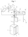
- Fig. 1 shows a schematic representation of a Elevator system with the inventive Safety device.
- Elevator shaft movable elevator car 1 with doors 2 is by means of rope strand 3 with one in the elevator shaft movable counterweight 4 connected.
- An electric motor 5 drives an input shaft 6 of a transmission 7.
- the output shaft 8 of the transmission 7 is the cable strand 3 driving and carrying traction sheave 9 arranged.
- the Gear 7 has, for example, one on input shaft 6 arranged worm 7.1 and one on the output shaft 8 arranged worm wheel 7.2 on. Other types of gears like for example, a spur gear is also conceivable.
- a Service brake 10 is provided at the gear-side end of the input shaft 6 .
- a first one Encoder 11 for detecting the speed of the input shaft 6 arranged.
- a second encoder 12 for detecting the speed of the Output shaft 8 arranged.
- the second Encoder 12 as shown with a broken line, instead the speed of the output shaft 8 the speed of the Traction sheave 9 or the movement of the rope strand 3 to capture.
- the signals from the encoders 11, 12 become one Evaluation electronics 13 supplied, depending on the result of the Evaluation of a safety circuit 14 not one shown elevator control interrupts and / or Rope brake 15 activated.
- Evaluation electronics 13 and encoder 11, 12 form a detector for monitoring the speed the input shaft 6 and the output shaft 8 and Generation of actuator signals for example Rope brake 15.
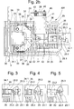
- FIG. 2a shows the mode of operation of the inventive Cable brake 15, which essentially consists of one side a housing 20 arranged pantograph 21, wherein the pantograph 21 is made up of two pairs of levers.
- On Lever pair consists of a first lever 22 which ends articulated with a movably mounted on the housing 20 Release rod 23 and articulated at the other end with a second one Lever 24 is connected, the second lever 24th is articulated at the other end to the housing 20.
- at Normal operation is the movably mounted on the housing 20 Release rod 23 by means of a rotatable on the housing 20th stored trigger lever 25 held.
- the braking force BK is mathematical as a function of current position of the brake plate 26 can be shown it can be shown that the speed ratio the speed of the trigger rod 23 Speed of the brake plate 26 inversely to the ratio the spring force FK to the braking force BK.
- the current one Position of the brake plate 26 during the triggering process stands in relation to the current position of the trigger bar 23, the length of the levers 22, 22 and their angle to Horizontal as well as the position of the break point of the Pair of levers and the position of the stop 32 with respect to Axis of rotation 33 are decisive. From the above relation can the relation of the braking force BK to the spring force FK is calculated be, the braking force BK equal to the spring force FK multiplied by the ratio of the speed of the Release rod 23 for the speed of the brake plate 26 is.
- the rope brake 15 consists of the housing 20 on which a first Brake plate 30 is fixed and from the second Brake plate 26 which is movably arranged on the housing 20.
- the rope strand 3 runs between the Brake plates 30.26 through.
- the rope strand 3 is by means of a rope guide, not shown, in a through the Brake plates 30,26 spanned level.
- the second Brake plate 26 is on a pressure plate 31 with a boom 31.1 attached, with stops 31.1 or 32.1 on the boom Roles are arranged.
- the stops 32 are by means of second lever 24 of the pantograph 21 operated, the second lever 24 at one end on an axis of rotation 33 with the Housing 20 and the other end articulated with the first lever 22 connected is.
- the other end of the first lever 22 is hingedly connected to a trigger plate 34, which means a clamping nut 35 with the release rod 23 in connection stands.
- the clamping nut 35 serves to reset the Compression springs 36.
- Compression springs 36 that generate the spring force FK are at one end on the housing 20 and at the other end on one Spring plate 37 of the trigger plate 34 is arranged. Return springs 38 ensure the resetting of the Pressure plate 31.
- the trigger lever 25 consists of a first leg 25.1 and from a second leg 25.2 with crossbar 25.3, the release lever 25 on a first axis 25.4 is rotatably mounted.
- the Crossbar 25.3 with a nose 23.1 of the release rod 23. Die Position of the nose 23.1 is not shown Sensor, for example using a limit switch monitored.
- Electromagnet 40 On a bracket 39 is arranged Electromagnet 40, which in the activated state Mass element 41 holds. Bracket 39, electromagnet 40, Mass element 41, guide rods 42 and release lever 25 form the trigger mechanism AM.
- FIG Rope brake 15 shows section A of FIG Rope brake 15 in the event of a trigger.
- Fig. 3 shows the rope brake 15 during normal operation.
- the crossbar 25.3 is with the nose 23.1 locked.
- the rope strand 3 runs freely between the Brake plates 30.26 through.
- Fig. 4 shows the location of the Crossbar 25.3 after the impact of the mass element 41 on the first leg 25.1 of the release lever 25.
- the nose 23.1 is released, the braking of the rope strand 3 about to start. 5 shows the position of the nose 23.1, after the pantographs 21 to the brake plates 30, 26 Have pressed rope strand 3.
- the compression springs 36 are reset by means of the Clamping nut 35, which is in a thread 34.1 of the release plate 34 and engages in a thread 23.2 of the release rod 23, the threads 23.2, 34.1 are in opposite directions. Go berserk the clamping nut 35, the trigger rod 23 is moved back, until the nose 23.1 is again in the position shown in FIG. 3 and the cross bar 25.3 can return to its starting position, in which the nose 23.1 latches with the crossbar 25.3. Then the clamping nut 35 in the opposite direction rotated, the total length of the release rod 23 and the release plate 34 is shortened and the compression springs 36 be excited again.
- FIG. 6 and 7 show a spatial representation of the Rope brake 15 according to the invention during normal operation.
- Extension 31.1 with stops 32, pantograph 21, Mass element 41, guide rods 42, electromagnet 40, Springs 43 and release lever 25 are on both sides of the Compression springs 36 arranged.
- At 44 is one Adjustment device for the first brake plate 30 designated.
- Fig. 7 is the mass element for better understanding 41 and the adjusting device 44 and the first brake plate 30 has been removed.
- FIG. 6a shows an embodiment variant for triggering the Mass element 41.
- This variant prevents the rope brake is not wanted is triggered.
- the electromagnet operates 40 a pawl 46, which releases the mass element 41.
- the Pawl 46 is rotatable at one end on housing 20 connected axis 47 mounted. The other end is the jack 46 articulated with a push rod 48 of the electromagnet 40 connected. Which symbolized with an arrow PL Linear movement of the push rod 48 causes one with a Arrow PR symbolized rotary movement of the pawl 46, whereby the pawl 46 that is held on a recess 49 Mass element 41 releases.
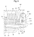
- FIG. 8 shows a further embodiment variant of the Brake release and Fig. 9 details of brake release.
- the bolt 40.1 is withdrawn and the mass element 41 falls on the U-shaped release lever 25 consisting of the first leg 25.1 and the second leg 25.2, the mass element 41 on the rope brake side corresponding leg 25.1 of the U falls and the Release lever 25 about the axis 25.4 in the Release position moved.
- Fig. 9 shows details of the Release mechanism AM of the rope brake 15 according to FIG. 8.
- the Release lever 25 is in its release position with a bold line shown.
- One in an elongated slot 20.1 of the housing 20 guided bolt 20.2 holds the release rod 23 on one Nose 23.3 back, the movement of the bolt 20.2 after below by means of a nose 25.5 of the first release lever 25 is prevented.
- the path of the bolt is 20.2 down free. Under the action of the spring force of the Compression springs 36 will trigger bar 23 and Release plate 34 moves in the direction of the cable strand 3 and the braking process is initiated.
Landscapes
- Engineering & Computer Science (AREA)
- Mechanical Engineering (AREA)
- Maintenance And Inspection Apparatuses For Elevators (AREA)
- Braking Arrangements (AREA)
Priority Applications (1)
| Application Number | Priority Date | Filing Date | Title |
|---|---|---|---|
| EP04013227A EP1489039B1 (fr) | 2003-06-16 | 2004-06-04 | Frein de câble pour ascenseur |
Applications Claiming Priority (3)
| Application Number | Priority Date | Filing Date | Title |
|---|---|---|---|
| EP03405431 | 2003-06-16 | ||
| EP03405431 | 2003-06-16 | ||
| EP04013227A EP1489039B1 (fr) | 2003-06-16 | 2004-06-04 | Frein de câble pour ascenseur |
Publications (3)
| Publication Number | Publication Date |
|---|---|
| EP1489039A2 true EP1489039A2 (fr) | 2004-12-22 |
| EP1489039A3 EP1489039A3 (fr) | 2005-02-02 |
| EP1489039B1 EP1489039B1 (fr) | 2007-07-25 |
Family
ID=34924343
Family Applications (1)
| Application Number | Title | Priority Date | Filing Date |
|---|---|---|---|
| EP04013227A Expired - Lifetime EP1489039B1 (fr) | 2003-06-16 | 2004-06-04 | Frein de câble pour ascenseur |
Country Status (4)
| Country | Link |
|---|---|
| EP (1) | EP1489039B1 (fr) |
| AT (1) | ATE367996T1 (fr) |
| DE (1) | DE502004004416D1 (fr) |
| ES (1) | ES2291775T3 (fr) |
Families Citing this family (1)
| Publication number | Priority date | Publication date | Assignee | Title |
|---|---|---|---|---|
| CH707833A1 (de) * | 2013-03-28 | 2014-09-30 | Phoenix Mecano Komponenten Ag | Aufzugsanlage mit einer Bremsvorrichtung. |
Family Cites Families (4)
| Publication number | Priority date | Publication date | Assignee | Title |
|---|---|---|---|---|
| DE2904989A1 (de) * | 1979-02-09 | 1980-08-21 | Sonnberger Jun | Abseilgeraet |
| DE59208926D1 (de) * | 1991-11-18 | 1997-10-30 | Inventio Ag | Vorrichtung zum Auslösen von Sicherheitseinrichtungen |
| US5228540A (en) * | 1992-07-24 | 1993-07-20 | Hollister-Whitney Elevator Corp. | Elevator car brake with shoes actuated by springs |
| DE19635244C2 (de) * | 1996-08-30 | 2000-08-10 | Wittur Aufzugteile Gmbh & Co | Sicherheits- Bremsvorrichtung für Seilförderanlagen |
-
2004
- 2004-06-04 AT AT04013227T patent/ATE367996T1/de not_active IP Right Cessation
- 2004-06-04 EP EP04013227A patent/EP1489039B1/fr not_active Expired - Lifetime
- 2004-06-04 DE DE502004004416T patent/DE502004004416D1/de not_active Expired - Lifetime
- 2004-06-04 ES ES04013227T patent/ES2291775T3/es not_active Expired - Lifetime
Also Published As
| Publication number | Publication date |
|---|---|
| ES2291775T3 (es) | 2008-03-01 |
| ATE367996T1 (de) | 2007-08-15 |
| EP1489039B1 (fr) | 2007-07-25 |
| EP1489039A3 (fr) | 2005-02-02 |
| DE502004004416D1 (de) | 2007-09-06 |
Similar Documents
| Publication | Publication Date | Title |
|---|---|---|
| EP1637495B1 (fr) | Frein à cable pour ascenseur | |
| EP1733992B2 (fr) | Dispositif parachute | |
| DE102013111385A1 (de) | Auslösevorrichtung einer Fangvorrichtung für eine Aufzugskabine einer Aufzugsanlage | |
| EP2651807B1 (fr) | Dispositif de surveillance permettant de constater un départ indésirable d'une cabine d'ascenseur à l'arrêt | |
| EP2558396A1 (fr) | Actionneur pour un dispositif de freinage et une installation d'ascenseur | |
| WO2015071188A1 (fr) | Parachute pour ascenseur | |
| WO2016074842A1 (fr) | Serrure de véhicule automobile | |
| DE2753445A1 (de) | Sicherheitsvorrichtung fuer eine fahrstuhlanlage | |
| DE102012016336A1 (de) | Geschwindigkeitsbegrenzer für ein Aufzugsystem | |
| WO2023134980A1 (fr) | Unité de libération pour actionner un dispositif de frein d'ascenseur | |
| EP2125389A1 (fr) | Ascenseur | |
| EP1400476B1 (fr) | Parachute pour ascenseurs | |
| EP2345618A1 (fr) | Bordure de sécurité d'une porte de cabine | |
| EP3153454B1 (fr) | Verrouillage de porte | |
| EP1489039A2 (fr) | Frein de câble pour ascenseur | |
| EP1841679B1 (fr) | Dispositif de freinage d'urgence destine a une cabine d'ascenseur | |
| EP0947460A1 (fr) | Dispositif de libération de secours | |
| DE102006047644B4 (de) | Autonome Exzenterfangvorrichtung | |
| EP3798174B1 (fr) | Dispositif de déclenchement pour un parachute | |
| DE69105429T2 (de) | Entlüftungsvorrichtung für Gebäudefassaden. | |
| DE7426752U (de) | Rolltor mit Absturzsicherung | |
| DE2708221C2 (de) | Antrieb für ein Tor | |
| DE10112043C2 (de) | Beschickungseinrichtung für Öfen | |
| AT248492B (de) | Sicherheitsbremseinrichtung für durch Seile gezogene Schienenfahrzeuge | |
| HK1089742B (en) | Cable brake for an elevator |
Legal Events
| Date | Code | Title | Description |
|---|---|---|---|
| PUAI | Public reference made under article 153(3) epc to a published international application that has entered the european phase |
Free format text: ORIGINAL CODE: 0009012 |
|
| PUAL | Search report despatched |
Free format text: ORIGINAL CODE: 0009013 |
|
| AK | Designated contracting states |
Kind code of ref document: A2 Designated state(s): AT BE BG CH CY CZ DE DK EE ES FI FR GB GR HU IE IT LI LU MC NL PL PT RO SE SI SK TR |
|
| AX | Request for extension of the european patent |
Extension state: AL HR LT LV MK |
|
| AK | Designated contracting states |
Kind code of ref document: A3 Designated state(s): AT BE BG CH CY CZ DE DK EE ES FI FR GB GR HU IE IT LI LU MC NL PL PT RO SE SI SK TR |
|
| AX | Request for extension of the european patent |
Extension state: AL HR LT LV MK |
|
| 17P | Request for examination filed |
Effective date: 20050714 |
|
| AKX | Designation fees paid |
Designated state(s): AT BE BG CH CY CZ DE DK EE ES FI FR GB GR HU IE IT LI LU MC NL PL PT RO SE SI SK TR |
|
| GRAP | Despatch of communication of intention to grant a patent |
Free format text: ORIGINAL CODE: EPIDOSNIGR1 |
|
| GRAS | Grant fee paid |
Free format text: ORIGINAL CODE: EPIDOSNIGR3 |
|
| GRAA | (expected) grant |
Free format text: ORIGINAL CODE: 0009210 |
|
| AK | Designated contracting states |
Kind code of ref document: B1 Designated state(s): AT BE BG CH CY CZ DE DK EE ES FI FR GB GR HU IE IT LI LU MC NL PL PT RO SE SI SK TR |
|
| REG | Reference to a national code |
Ref country code: GB Ref legal event code: FG4D Free format text: NOT ENGLISH |
|
| REG | Reference to a national code |
Ref country code: CH Ref legal event code: EP |
|
| REG | Reference to a national code |
Ref country code: IE Ref legal event code: FG4D Free format text: LANGUAGE OF EP DOCUMENT: GERMAN |
|
| REF | Corresponds to: |
Ref document number: 502004004416 Country of ref document: DE Date of ref document: 20070906 Kind code of ref document: P |
|
| GBT | Gb: translation of ep patent filed (gb section 77(6)(a)/1977) |
Effective date: 20070903 |
|
| ET | Fr: translation filed | ||
| PG25 | Lapsed in a contracting state [announced via postgrant information from national office to epo] |
Ref country code: NL Free format text: LAPSE BECAUSE OF FAILURE TO SUBMIT A TRANSLATION OF THE DESCRIPTION OR TO PAY THE FEE WITHIN THE PRESCRIBED TIME-LIMIT Effective date: 20070725 Ref country code: FI Free format text: LAPSE BECAUSE OF FAILURE TO SUBMIT A TRANSLATION OF THE DESCRIPTION OR TO PAY THE FEE WITHIN THE PRESCRIBED TIME-LIMIT Effective date: 20070725 Ref country code: BG Free format text: LAPSE BECAUSE OF FAILURE TO SUBMIT A TRANSLATION OF THE DESCRIPTION OR TO PAY THE FEE WITHIN THE PRESCRIBED TIME-LIMIT Effective date: 20071025 Ref country code: PT Free format text: LAPSE BECAUSE OF FAILURE TO SUBMIT A TRANSLATION OF THE DESCRIPTION OR TO PAY THE FEE WITHIN THE PRESCRIBED TIME-LIMIT Effective date: 20071226 |
|
| NLV1 | Nl: lapsed or annulled due to failure to fulfill the requirements of art. 29p and 29m of the patents act | ||
| PG25 | Lapsed in a contracting state [announced via postgrant information from national office to epo] |
Ref country code: PL Free format text: LAPSE BECAUSE OF FAILURE TO SUBMIT A TRANSLATION OF THE DESCRIPTION OR TO PAY THE FEE WITHIN THE PRESCRIBED TIME-LIMIT Effective date: 20070725 |
|
| REG | Reference to a national code |
Ref country code: ES Ref legal event code: FG2A Ref document number: 2291775 Country of ref document: ES Kind code of ref document: T3 |
|
| REG | Reference to a national code |
Ref country code: IE Ref legal event code: FD4D |
|
| PG25 | Lapsed in a contracting state [announced via postgrant information from national office to epo] |
Ref country code: DK Free format text: LAPSE BECAUSE OF FAILURE TO SUBMIT A TRANSLATION OF THE DESCRIPTION OR TO PAY THE FEE WITHIN THE PRESCRIBED TIME-LIMIT Effective date: 20070725 Ref country code: GR Free format text: LAPSE BECAUSE OF FAILURE TO SUBMIT A TRANSLATION OF THE DESCRIPTION OR TO PAY THE FEE WITHIN THE PRESCRIBED TIME-LIMIT Effective date: 20071026 |
|
| PG25 | Lapsed in a contracting state [announced via postgrant information from national office to epo] |
Ref country code: SK Free format text: LAPSE BECAUSE OF FAILURE TO SUBMIT A TRANSLATION OF THE DESCRIPTION OR TO PAY THE FEE WITHIN THE PRESCRIBED TIME-LIMIT Effective date: 20070725 Ref country code: CZ Free format text: LAPSE BECAUSE OF FAILURE TO SUBMIT A TRANSLATION OF THE DESCRIPTION OR TO PAY THE FEE WITHIN THE PRESCRIBED TIME-LIMIT Effective date: 20070725 Ref country code: IE Free format text: LAPSE BECAUSE OF FAILURE TO SUBMIT A TRANSLATION OF THE DESCRIPTION OR TO PAY THE FEE WITHIN THE PRESCRIBED TIME-LIMIT Effective date: 20070725 |
|
| PLBE | No opposition filed within time limit |
Free format text: ORIGINAL CODE: 0009261 |
|
| STAA | Information on the status of an ep patent application or granted ep patent |
Free format text: STATUS: NO OPPOSITION FILED WITHIN TIME LIMIT |
|
| PG25 | Lapsed in a contracting state [announced via postgrant information from national office to epo] |
Ref country code: RO Free format text: LAPSE BECAUSE OF FAILURE TO SUBMIT A TRANSLATION OF THE DESCRIPTION OR TO PAY THE FEE WITHIN THE PRESCRIBED TIME-LIMIT Effective date: 20070725 Ref country code: SE Free format text: LAPSE BECAUSE OF FAILURE TO SUBMIT A TRANSLATION OF THE DESCRIPTION OR TO PAY THE FEE WITHIN THE PRESCRIBED TIME-LIMIT Effective date: 20071025 |
|
| 26N | No opposition filed |
Effective date: 20080428 |
|
| BERE | Be: lapsed |
Owner name: INVENTIO A.G. Effective date: 20080630 |
|
| PG25 | Lapsed in a contracting state [announced via postgrant information from national office to epo] |
Ref country code: MC Free format text: LAPSE BECAUSE OF NON-PAYMENT OF DUE FEES Effective date: 20080630 |
|
| PG25 | Lapsed in a contracting state [announced via postgrant information from national office to epo] |
Ref country code: BE Free format text: LAPSE BECAUSE OF NON-PAYMENT OF DUE FEES Effective date: 20080630 |
|
| PG25 | Lapsed in a contracting state [announced via postgrant information from national office to epo] |
Ref country code: EE Free format text: LAPSE BECAUSE OF FAILURE TO SUBMIT A TRANSLATION OF THE DESCRIPTION OR TO PAY THE FEE WITHIN THE PRESCRIBED TIME-LIMIT Effective date: 20070725 |
|
| PG25 | Lapsed in a contracting state [announced via postgrant information from national office to epo] |
Ref country code: SI Free format text: LAPSE BECAUSE OF FAILURE TO SUBMIT A TRANSLATION OF THE DESCRIPTION OR TO PAY THE FEE WITHIN THE PRESCRIBED TIME-LIMIT Effective date: 20070725 |
|
| PG25 | Lapsed in a contracting state [announced via postgrant information from national office to epo] |
Ref country code: CY Free format text: LAPSE BECAUSE OF FAILURE TO SUBMIT A TRANSLATION OF THE DESCRIPTION OR TO PAY THE FEE WITHIN THE PRESCRIBED TIME-LIMIT Effective date: 20070725 |
|
| PGFP | Annual fee paid to national office [announced via postgrant information from national office to epo] |
Ref country code: ES Payment date: 20090623 Year of fee payment: 6 |
|
| PGFP | Annual fee paid to national office [announced via postgrant information from national office to epo] |
Ref country code: AT Payment date: 20090615 Year of fee payment: 6 |
|
| PGFP | Annual fee paid to national office [announced via postgrant information from national office to epo] |
Ref country code: CH Payment date: 20090917 Year of fee payment: 6 |
|
| PG25 | Lapsed in a contracting state [announced via postgrant information from national office to epo] |
Ref country code: HU Free format text: LAPSE BECAUSE OF FAILURE TO SUBMIT A TRANSLATION OF THE DESCRIPTION OR TO PAY THE FEE WITHIN THE PRESCRIBED TIME-LIMIT Effective date: 20080126 Ref country code: LU Free format text: LAPSE BECAUSE OF NON-PAYMENT OF DUE FEES Effective date: 20080604 |
|
| PG25 | Lapsed in a contracting state [announced via postgrant information from national office to epo] |
Ref country code: TR Free format text: LAPSE BECAUSE OF FAILURE TO SUBMIT A TRANSLATION OF THE DESCRIPTION OR TO PAY THE FEE WITHIN THE PRESCRIBED TIME-LIMIT Effective date: 20070725 |
|
| REG | Reference to a national code |
Ref country code: CH Ref legal event code: PL |
|
| PG25 | Lapsed in a contracting state [announced via postgrant information from national office to epo] |
Ref country code: IT Free format text: LAPSE BECAUSE OF NON-PAYMENT OF DUE FEES Effective date: 20080630 |
|
| PG25 | Lapsed in a contracting state [announced via postgrant information from national office to epo] |
Ref country code: CH Free format text: LAPSE BECAUSE OF NON-PAYMENT OF DUE FEES Effective date: 20100630 Ref country code: LI Free format text: LAPSE BECAUSE OF NON-PAYMENT OF DUE FEES Effective date: 20100630 |
|
| PG25 | Lapsed in a contracting state [announced via postgrant information from national office to epo] |
Ref country code: AT Free format text: LAPSE BECAUSE OF NON-PAYMENT OF DUE FEES Effective date: 20100604 |
|
| REG | Reference to a national code |
Ref country code: ES Ref legal event code: FD2A Effective date: 20110715 |
|
| PG25 | Lapsed in a contracting state [announced via postgrant information from national office to epo] |
Ref country code: ES Free format text: LAPSE BECAUSE OF NON-PAYMENT OF DUE FEES Effective date: 20110705 |
|
| REG | Reference to a national code |
Ref country code: DE Ref legal event code: R084 Ref document number: 502004004416 Country of ref document: DE Effective date: 20110525 |
|
| PG25 | Lapsed in a contracting state [announced via postgrant information from national office to epo] |
Ref country code: ES Free format text: LAPSE BECAUSE OF NON-PAYMENT OF DUE FEES Effective date: 20100605 |
|
| PGFP | Annual fee paid to national office [announced via postgrant information from national office to epo] |
Ref country code: DE Payment date: 20120622 Year of fee payment: 9 |
|
| PGFP | Annual fee paid to national office [announced via postgrant information from national office to epo] |
Ref country code: FR Payment date: 20120705 Year of fee payment: 9 Ref country code: GB Payment date: 20120622 Year of fee payment: 9 |
|
| GBPC | Gb: european patent ceased through non-payment of renewal fee |
Effective date: 20130604 |
|
| REG | Reference to a national code |
Ref country code: FR Ref legal event code: ST Effective date: 20140228 |
|
| REG | Reference to a national code |
Ref country code: DE Ref legal event code: R119 Ref document number: 502004004416 Country of ref document: DE Effective date: 20140101 |
|
| PG25 | Lapsed in a contracting state [announced via postgrant information from national office to epo] |
Ref country code: GB Free format text: LAPSE BECAUSE OF NON-PAYMENT OF DUE FEES Effective date: 20130604 Ref country code: DE Free format text: LAPSE BECAUSE OF NON-PAYMENT OF DUE FEES Effective date: 20140101 |
|
| PG25 | Lapsed in a contracting state [announced via postgrant information from national office to epo] |
Ref country code: FR Free format text: LAPSE BECAUSE OF NON-PAYMENT OF DUE FEES Effective date: 20130701 |