EP1489557A2 - Procédé de détection de contours adaptatifs - Google Patents
Procédé de détection de contours adaptatifs Download PDFInfo
- Publication number
- EP1489557A2 EP1489557A2 EP04013431A EP04013431A EP1489557A2 EP 1489557 A2 EP1489557 A2 EP 1489557A2 EP 04013431 A EP04013431 A EP 04013431A EP 04013431 A EP04013431 A EP 04013431A EP 1489557 A2 EP1489557 A2 EP 1489557A2
- Authority
- EP
- European Patent Office
- Prior art keywords
- brightness
- edge
- surf
- bgrd
- background
- Prior art date
- Legal status (The legal status is an assumption and is not a legal conclusion. Google has not performed a legal analysis and makes no representation as to the accuracy of the status listed.)
- Withdrawn
Links
Images



Classifications
-
- G—PHYSICS
- G06—COMPUTING OR CALCULATING; COUNTING
- G06T—IMAGE DATA PROCESSING OR GENERATION, IN GENERAL
- G06T7/00—Image analysis
- G06T7/10—Segmentation; Edge detection
- G06T7/12—Edge-based segmentation
-
- G—PHYSICS
- G06—COMPUTING OR CALCULATING; COUNTING
- G06T—IMAGE DATA PROCESSING OR GENERATION, IN GENERAL
- G06T2207/00—Indexing scheme for image analysis or image enhancement
- G06T2207/20—Special algorithmic details
- G06T2207/20004—Adaptive image processing
- G06T2207/20008—Globally adaptive
-
- G—PHYSICS
- G06—COMPUTING OR CALCULATING; COUNTING
- G06T—IMAGE DATA PROCESSING OR GENERATION, IN GENERAL
- G06T2207/00—Indexing scheme for image analysis or image enhancement
- G06T2207/30—Subject of image; Context of image processing
- G06T2207/30108—Industrial image inspection
- G06T2207/30164—Workpiece; Machine component
Definitions
- the invention relates to a method according to the preamble of claim 1.
- the invention relates to the detection of an edge on a light and shadow image obtained by means of an image processing system, regardless of the lighting conditions (e.g. different local brightness at the edge as with Wood), the sharpness of the edge image (e.g. an oblique edge) and the complexity of the Edge (e.g. double edge as with a wooden board with a bark).
- the lighting conditions e.g. different local brightness at the edge as with Wood
- the sharpness of the edge image e.g. an oblique edge
- the complexity of the Edge e.g. double edge as with a wooden board with a bark.
- Edge detection determines the use of each of these methods and is therefore from of considerable economic importance.
- Another method (DE 19902401 C2) first provides for binarization of the image. Edge detection is carried out after binarization. A binarization a threshold value must be formed. This can either be specified or can be determined dynamically from the image content.
- the specified threshold value (DE 4131778 C2) does not take into account Deviations, e.g. Lighting fluctuations on a series of successive Recordings or on different areas of the current image are available. there the image to be examined cannot be binarized properly, which is also an incorrect one Detection of the edges caused.
- Determining the threshold value directly from the content of the current image is one Possibility to adapt the edge detection method to the image to be examined. Therefore you use e.g. a histogram (EP 0750272 B1, EP 0807297 B1) which shows the frequency of individual gray values that appear in the image. From the absolute or local maximum or a minimum of the histogram, a binarization threshold can be found.
- edge detection In addition, binarization of the image influences the edge detection and thus Like any other image filtering, it falsifies the result of the edge detection. Therefore, the edge detection should best be done on the original gray scale image.
- an edge can be obtained directly from a gray-scale image using a Edge model can determine (industrial image processing / Christian Demant, Bernd Strings-Abel, Peter Waszkewitz. - Berlin; Heidelberg: Springer, 1998). This is particularly true the case when the location of the edge is already known. Finding edges with one Edge models are usually carried out on search lines in a certain direction.
- the above methods can be either one Use a histogram or just a grayscale profile to detect an edge and above
- the relevant parameters are generally specified, not flexible and at the same time ensure explicit edge detection on an image to be examined.
- the invention has for its object to a method for edge detection create a simple, secure, self-adapting to the content of the image to be examined and at the same time allows explicit detection of the edges of different objects. It will recognized whether there is an edge in an area to be examined, and then the exact localization of the edge sought. All parameters required for this should be determined dynamically from the image to be examined and further used only for this image become.
- Such a method is e.g. for controllers ("adaptive controllers") for a long time the Technology.
- the method described here can also be used as an adaptive method Edge detection can be called.
- the detection of an edge in a test area of an image to be examined is carried out along a search line.
- the histogram is obtained from the entire test area and the gray value profile along the search line in the test area. It is assumed that the object and the background, the transition of which forms the desired edge, have the brightness I surf ( surface ) on the surface and I bgrd ( background ) on the background, the object being, for example, always lighter than the background , Otherwise, the roles of the object and the background should be reversed.
- the histogram of an image area that is always and securely represents only the background to be formed. It is assumed that different Objects on the same or similar background are to be examined.
- the histogram and the grayscale profile are to be treated as Gaussian distributions and used together as output data for edge detection, from whose edge-specific minimum brightness I 0 and an edge-specific minimum brightness gradient ⁇ I 0 (a minimum difference in gray values) and the length of the test section L 0 is to be determined dynamically, with the aid of which an edge is sought.
- the test section L 0 on which the local maximum brightness I max and the local brightness gradient ⁇ I are determined and correspondingly compared with the edge-specific minimum brightness I 0 and the edge-specific minimum brightness gradient ⁇ I 0 , is to be shifted along the search line.
- a histogram is a frequency distribution of the brightness on an object or his background.
- the content of the image usually has one with the spatial frequency declining amplitude spectrum, whereas the noise is in the frequency range has a constant spectrum.
- the histogram as well as the gray value profile also a Gaussian profile (methods of digital image signal processing / Piero Zamperoni.-Braunschweig / Wiesbaden: Friedr. Vieweg & Sohn, 1989) or one of several Gaussian distribution resulting profile (digital image processing / Bernd Jähne. - 4th ed. - Berlin, Heidelberg, etc .: Springer, 1997).
- the brightness value that occurs most frequently on the surface of an object can be defined as the brightness of this object.
- This method has a correct object brightness I surf for the surface to be examined, as long as a disturbance with a certain brightness value does not have a greater or comparable frequency than that of the object brightness I surf . Then it is no longer possible to distinguish between the fault and the main surface itself (eg chess board). The same applies to the background, which has a background brightness I bgrd .
- the general background brightness I bgrd_gen and the brightness separation value I sprt serve only as orientation values in order to be able to determine and use all further required threshold values exclusively locally.
- the use of the luminance separation value I sprt ensures reliable and unambiguous method to the object brightness I surf and to determine the background brightness I bgrd, regardless of how large the maximum values of the frequencies surf at the points I and I are bgrd, and in what proportions these maximum values to stand by each other.
- the test area may contain much more background than areas on the object itself.
- the standard deviation ⁇ des Gaussian profile can be determined.
- the test section L 0 also defines an image-specific and curve-characteristic length that is to be used for the further edge search.
- the first position corresponds to the end point of the test section L 0 when both of the above conditions are met for the first time.
- the second position corresponds to the starting point of the test route L 0 when both of the above conditions are met for the last time.
- the general background brightness I bgrd_gen both for further be used to be investigated areas of current uptake and for further recording as local background brightness I bgrd , because the reflection conditions change fundamentally on the object but not on the background.
- the histogram represents a Gaussian profile from an area that is on the background and only on the background
- an image-specific general object brightness I surf_gen should first be determined from an area which is on the object and only on the object. If an edge of the same or similar object is searched on different backgrounds, according to claim 4, the general object brightness I surf_gen both further to be examined areas in the entire current image are also used for more images under the same recording conditions as a local object brightness I surf as.
- I sprt I surf_gen * ⁇ 1 ,
- the histogram represents a Gaussian profile from an area that is on the object and only on the object
- the values I surf and I bgrd are used to calculate, among other things, the lower brightness threshold value I sprt_dark and the upper brightness threshold value I sprt_light , which serve to separate the middle area of the gray value profile from its edge areas, which from the background or the object originate and can therefore be burdened with possible malfunctions.
- the standard deviation ⁇ of the grayscale profile can be determined with much higher accuracy and certainty on the separated area of the curve with the help of the known conventional calculation methods, eg the method of least squares.
- the length of the test section L 0 can be determined on a special calibration test area which contains a typical edge and can further be used for the entire image.
- this test route L 0 is site-specific, it represents a length that will not differ very much at different points in the image under comparable lighting and focus conditions. Therefore, the test route L 0 can be used as an image-specific constant without loss of generalization.
- Such a double edge consists of two transition areas: between the Background and the intermediate zone (bark) and between the intermediate zone (bark) and the Object (wood). Each transition area has its own edge. Both the gray scale profile and even the histogram of a double edge still has a Gaussian profile, with each Profile (gray scale profile or histogram) from a combination of two Gaussian distributions consists.
- the detection of a double edge should be carried out as follows.
- Sprt with the general brightness separation value I is found in the range of [I dark - I sprt] of the histogram, the local background brightness I bgrd. This is used to calculate the edge-specific parameters - the edge-specific minimum brightness I 0 _bgrd and the edge-specific minimum brightness gradient ⁇ I 0_ bgrd - to search for an edge between the background and the intermediate zone.
- the local object brightness I surf is found in the area of [ I sprt - I light ] of the histogram and is used to calculate the edge-specific parameters - the edge-specific minimum brightness I 0_ surf and the edge-specific minimum brightness gradient ⁇ I 0 _surf , - by the Search for an edge to perform between the intermediate zone and the object.
- I bgrd I bgrd_gen
- the gray value profile should be searched from the side of the background with the test section L 0 for each edge to be searched.
- an edge in the transition area between the intermediate zone and the object should be sought first, because this is much more pronounced because of the strong brightness of the object than the edge in the transition area between the background and the intermediate zone.
- the search for the edge in the transition area between the background and the intermediate zone should start from the beginning of the test area up to the position at which the edge already determined between the Intermediate zone and the object is located.
- the portion of the background and the object in the test area should be large enough compared to the portion of the area in between. This is to ensure a significantly more precise and unambiguous determination of the object brightness I surf and the background brightness I bgrd from the histogram.
- a complex multiple edge contains more than two simple edges, each of them should be recognized according to claim 15 as follows.
- the brightest edge is first searched for the double edge detection method described above.
- the first edge found then has a brightness which can further be used as the local object brightness I surf_loc for the search for the next darker edge.
- This chain search all other edges are tracked down. However, all search steps should be coordinated with the background brightness I bgrd so that the edge detection process does not go beyond the background.
- a further possibility of recognizing each individual edge of a complex multiple edge is, according to claim 16 , that the darkest edge is first searched for using the method described above for detecting a double edge. The first edge found then has a brightness which can further be used as the local background brightness I bgrd_loc for the search for the next brighter edge. With this chain search all other edges are tracked down. However, all search steps should be coordinated with the object brightness I surf , so that the edge detection process does not extend beyond the object.
- the search line which is formed along a gray value profile, should lie transversely to the searched edge, but within the test area.
- the gray value profile can be formed both from a single row of pixels and as a mean value curve from a plurality of adjacent rows of pixels lying parallel to the search line 6 .
- theorem digital image processing / Bernd Jähne. - 4th ed. - Berlin, Heidelberg, etc .: Springer, 1997) is said to be the sampling length of a signal in order to falsify it Avoid signal when sampling, contain at least three sampling points.
- the Number of scanning pixels must be at least three.
- the Edge detection can be strongly influenced by random interference. Therefore can be the number of pixel rows drawn to form the gray value profile, which along the Search line should be won, for example, be set as three.
- Both the gray scale profile and the histogram can contain certain random disturbances or noise. According to claim 18 , only these curves but not the image itself are to be filtered in order to be able to carry out an error-free curve discussion.
- the method for adaptive edge detection mentioned here can be used for both Edge search, by converting the entire image into an edge image with the help various edge filters, as well as a binarization of the image, as well as a direct one Edge detection on a gray value image using fixed parameters such as edge height and edge length are dispensed with.
- a simple edge 3 of a light object 2 on a dark background 1 can be assumed as an example.
- the edge 3 is searched within the test area 4 (for example a rectangle) along the search line 5 .
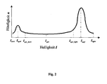
- both the object brightness I surf and the background brightness I bgrd can be determined. It is important to determine a brightness separation value I sprt from the general background brightness I bgrd _ gen beforehand in order to be able to clearly separate the corresponding parts of the histogram (background and object) (FIG. 2).
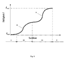
- This edge 3 is to be searched for on the gray value profile, which was formed along a search line 5, for example from the dark background area to the light object area (FIG. 3) .
- This search takes place within a test section L 0 , which is shifted along the search line, the local maximum brightness I max and the local brightness gradient ⁇ I being determined on the test section L 0, and accordingly with the edge-specific minimum brightness I 0 and with the edge-specific minimum Brightness slope ⁇ I 0 (minimum difference in gray values) is compared.
- the length of the test section L 0 , the size of the edge-specific minimum brightness value I 0 and the edge-specific minimum brightness gradient DI 0 are to be adapted to the local brightness conditions.
- the histogram and the gray value profile indicate Gaussian or a profile resulting from several Gaussian distributions. It means that these curves represent a normal Gaussian distribution and thus an exponential function and therefore have certain relationships between characteristic points.
- the brightness factor ⁇ 0 thus represents a minimal relationship between the brightness of the edge position 3 that is possible and the background 1 .
- the length of the test section L 0 must not be less than the distance between the turning point I turn and the edge point (background brightness I bgrd ) , which corresponds to the standard deviation ⁇ of the gray value profile .
- the test section L 0 must not exceed twice the size of the standard deviation ⁇ . Otherwise the test section becomes larger than the entire transition area 6 between the background 1 and the object 2 (FIG. 3).
- the edge search can only be carried out according to the edge-specific minimum brightness gradient ⁇ I 0 , without taking into account the edge-specific minimum brightness I 0 , which is an important condition for the adaptive edge detection. Therefore, the following condition should be met: ⁇ ⁇ L 0 ⁇ 2 * ⁇ .
- the local minimum brightness I min does not yet correspond to the object brightness ( I min ⁇ I surf ) but no longer corresponds to the background brightness (I min > I bgrd ) . It now points to a transition area 6 between the background 1 and the object 2, in which an edge 3 can be located, and thus determines the minimum brightness I 0 .
- the first position corresponds to the end point of the test section L 0 when conditions (8) and (9) are simultaneously met for the first time within the test section L 0 .
- the second position corresponds to the starting point of the test section L 0 when conditions (8) and (9) are fulfilled for the last time within the test section L 0 .
- the standard deviation of the gray value profile ⁇ can be determined using the known conventional calculation methods, for example the least squares method.
- object 2 to be examined may be assumed to be a radiating source. All of the parameters sought should be determined from the object brightness I surf .
- the edge-specific minimum brightness I 0 should be greater than the possible deviations from the background brightness I bgrd upwards, which can be caused by the noise (FIG. 3), and at the same time ensure the edge-specific minimum brightness gradient ⁇ I 0 , that of the minimum brightness factor ⁇ 0 and depends on the object brightness I surf . For this reason, further parameters necessary for edge detection should be defined. These parameters include the lower brightness threshold value I sprt_dark and the upper brightness threshold value I sprt_light (FIG. 2) as well as the lower safety distance ⁇ dark and the upper safety distance ⁇ light , which determine these brightness threshold values .
- the lower brightness threshold value I sprt_dark and the upper brightness threshold value I sprt_light separate the object and the background area on the gray value profile (FIG. 3) and on the histogram (FIG. 2) from the remaining areas which can be loaded with possible disturbances. This allows a practical curve discussion, which is required, for example, to determine the standard deviation ⁇ of the gray scale profile.
- the value range [ I bgrd - I sprt_dark ] can be used as a safety zone in the background area with the safety distance ⁇ dark between the background 1 and the point from which an edge 3 can be present for the curve discussion of both the gray value profile (FIG. 3) and the Histogram (Fig. 2) serve.
- the value range [ I sprt_light - I surf ] can be used as a safety zone in the object area with the safety distance ⁇ light between the point from which an edge 3 can no longer be present and the object 2 for the curve discussion of both the gray value profile (Fig. 3 ) and the histogram (Fig. 2) .
- the standard deviation ⁇ can then be determined from the gray value profile , namely from the range limited by the brightness threshold values I sprt_dark and I sprt_light , with the aid of known conventional calculation methods, for example the least squares method, with much higher accuracy and certainty.
- edge search can take place between the two positions mentioned above ( I sprt_dark , I sprt_light ).
- the length of the test section L 0 , the edge-specific minimum brightness I 0 and the edge-specific minimum brightness slope ⁇ I 0 can thus be determined dynamically and locally at the point to be examined.
- I lin represents the upper limit of the linearity range of the camera (e.g. 220 gray levels)
- the standard deviation ⁇ and thus the test section L 0 can be determined without a loss of generalization according to the method described above.
- edge-specific minimum brightness I 0_ bgrd I bgrd ⁇ 1 ,
- the edge-specific minimum brightness gradient ⁇ I 0_ bgrd should also be defined.
- the search for the edge 9 is no longer started in a possible wrong area, but only where the sought edge can be safely located.
- the corresponding edge-specific minimum brightness gradient ⁇ I 0_ surf should also be defined for the detection of this edge.
- the object brightness I surf is already known.
Landscapes
- Engineering & Computer Science (AREA)
- Computer Vision & Pattern Recognition (AREA)
- Physics & Mathematics (AREA)
- General Physics & Mathematics (AREA)
- Theoretical Computer Science (AREA)
- Image Analysis (AREA)
- Length Measuring Devices By Optical Means (AREA)
- Image Processing (AREA)
Applications Claiming Priority (2)
| Application Number | Priority Date | Filing Date | Title |
|---|---|---|---|
| DE10326031A DE10326031B4 (de) | 2003-06-10 | 2003-06-10 | Verfahren zur adaptiven Kantenerkennung |
| DE10326031 | 2003-06-10 |
Publications (2)
| Publication Number | Publication Date |
|---|---|
| EP1489557A2 true EP1489557A2 (fr) | 2004-12-22 |
| EP1489557A3 EP1489557A3 (fr) | 2006-05-31 |
Family
ID=33394810
Family Applications (1)
| Application Number | Title | Priority Date | Filing Date |
|---|---|---|---|
| EP04013431A Withdrawn EP1489557A3 (fr) | 2003-06-10 | 2004-06-08 | Procédé de détection de contours adaptatifs |
Country Status (2)
| Country | Link |
|---|---|
| EP (1) | EP1489557A3 (fr) |
| DE (1) | DE10326031B4 (fr) |
Cited By (7)
| Publication number | Priority date | Publication date | Assignee | Title |
|---|---|---|---|---|
| CN101968885A (zh) * | 2010-09-25 | 2011-02-09 | 西北工业大学 | 一种基于边缘和灰度的遥感图像变化检测方法 |
| CN105894474A (zh) * | 2016-04-20 | 2016-08-24 | 华北电力大学(保定) | 一种非线性图像增强方法及边缘检测方法 |
| CN115601623A (zh) * | 2022-11-04 | 2023-01-13 | 易思维(杭州)科技有限公司(Cn) | 一种视觉检测图像的目标区域获取方法及示教方法 |
| CN115830106A (zh) * | 2023-02-16 | 2023-03-21 | 智联信通科技股份有限公司 | 一种用于机房设备带电清洗的辅助定位方法 |
| CN116610990A (zh) * | 2023-04-06 | 2023-08-18 | 安徽继远软件有限公司 | 一种基于特征空间差异化的断路器隐患识别方法及装置 |
| CN117274142A (zh) * | 2022-06-15 | 2023-12-22 | 上海烟草集团有限责任公司 | 基于边缘搜索的裂缝宽度计算方法、装置、设备和介质 |
| CN117952958A (zh) * | 2024-03-21 | 2024-04-30 | 陕西中环机械有限责任公司 | 基于机器学习的鼓形滤网智慧健康检测方法 |
Families Citing this family (1)
| Publication number | Priority date | Publication date | Assignee | Title |
|---|---|---|---|---|
| DE102007045277A1 (de) * | 2007-09-18 | 2009-04-02 | Technische Universität Ilmenau | Verfahren zur Bestimmung des Kantenortes bei Antastung im Auflicht in der optischen Längenmesstechnik |
Family Cites Families (9)
| Publication number | Priority date | Publication date | Assignee | Title |
|---|---|---|---|---|
| US4859850A (en) * | 1987-01-12 | 1989-08-22 | Fuji Photo Film Co., Ltd. | Irradiation field recognizing method, and method of adjusting image processing conditions using the same |
| KR940007346B1 (ko) * | 1991-03-28 | 1994-08-13 | 삼성전자 주식회사 | 화상 처리 시스템의 엣지 검출 장치 |
| DE4435796C1 (de) * | 1994-10-06 | 1995-12-07 | Siemens Ag | Verfahren zur automatischen Erkennung von Kanten und Durchmessern in Bildern |
| JP3264932B2 (ja) * | 1995-01-31 | 2002-03-11 | ユナイテッド パーセル サービス オブ アメリカ インコーポレイテッド | テキストを含む画像における背景から前景を分離する方法及び装置 |
| EP0742431B1 (fr) * | 1995-05-10 | 2000-03-15 | Mahlo GmbH & Co. KG | Procédé et dispositif de détection de défauts dans des bandes de tissu ou analogue |
| JPH096957A (ja) * | 1995-06-23 | 1997-01-10 | Toshiba Corp | 濃度画像の2値化方法および画像2値化装置 |
| DE19549216C2 (de) * | 1995-12-30 | 1999-09-09 | Fraunhofer Ges Forschung | Verfahren zur Bildauswertung |
| DE19902401C2 (de) * | 1999-01-22 | 2001-02-01 | Wohlenberg Schneidesysteme Gmb | Verfahren und Vorrichtung zur Bestimmung der Geometrie von blattförmigem Gut oder Stapeln davon |
| CN1184796C (zh) * | 2001-07-26 | 2005-01-12 | 佳能株式会社 | 图象处理方法和设备以及图象处理系统 |
-
2003
- 2003-06-10 DE DE10326031A patent/DE10326031B4/de not_active Withdrawn - After Issue
-
2004
- 2004-06-08 EP EP04013431A patent/EP1489557A3/fr not_active Withdrawn
Cited By (9)
| Publication number | Priority date | Publication date | Assignee | Title |
|---|---|---|---|---|
| CN101968885A (zh) * | 2010-09-25 | 2011-02-09 | 西北工业大学 | 一种基于边缘和灰度的遥感图像变化检测方法 |
| CN105894474A (zh) * | 2016-04-20 | 2016-08-24 | 华北电力大学(保定) | 一种非线性图像增强方法及边缘检测方法 |
| CN117274142A (zh) * | 2022-06-15 | 2023-12-22 | 上海烟草集团有限责任公司 | 基于边缘搜索的裂缝宽度计算方法、装置、设备和介质 |
| CN115601623A (zh) * | 2022-11-04 | 2023-01-13 | 易思维(杭州)科技有限公司(Cn) | 一种视觉检测图像的目标区域获取方法及示教方法 |
| CN115830106A (zh) * | 2023-02-16 | 2023-03-21 | 智联信通科技股份有限公司 | 一种用于机房设备带电清洗的辅助定位方法 |
| CN115830106B (zh) * | 2023-02-16 | 2023-04-25 | 智联信通科技股份有限公司 | 一种用于机房设备带电清洗的辅助定位方法 |
| CN116610990A (zh) * | 2023-04-06 | 2023-08-18 | 安徽继远软件有限公司 | 一种基于特征空间差异化的断路器隐患识别方法及装置 |
| CN117952958A (zh) * | 2024-03-21 | 2024-04-30 | 陕西中环机械有限责任公司 | 基于机器学习的鼓形滤网智慧健康检测方法 |
| CN117952958B (zh) * | 2024-03-21 | 2024-06-07 | 陕西中环机械有限责任公司 | 基于机器学习的鼓形滤网智慧健康检测方法 |
Also Published As
| Publication number | Publication date |
|---|---|
| DE10326031B4 (de) | 2005-12-22 |
| EP1489557A3 (fr) | 2006-05-31 |
| DE10326031A1 (de) | 2005-01-13 |
Similar Documents
| Publication | Publication Date | Title |
|---|---|---|
| DE10326035B4 (de) | Verfahren zur adaptiven Fehlererkennung auf einer strukturierten Oberfläche | |
| DE10326033B4 (de) | Verfahren zur adaptiven Fehlererkennung auf einer inhomogenen Oberfläche | |
| DE19521346C2 (de) | Bilduntersuchungs/-Erkennungsverfahren, darin verwendetes Verfahren zur Erzeugung von Referenzdaten und Vorrichtungen dafür | |
| DE102011081668B4 (de) | Vorrichtung und Verfahren zur Bestimmung der Form des Endes einer Schweißnaht | |
| EP1609119A2 (fr) | Procede d'evaluation qualitative d'une matiere presentant au moins une caracteristique d'identification | |
| DE112018004661T5 (de) | Schattenerkennungsverfahren für ein Überwachungsvideobild, System davon undSchattenentfernungsverfahren | |
| EP1489557A2 (fr) | Procédé de détection de contours adaptatifs | |
| DE102020120887A1 (de) | Verfahren zum erfassen einer einhängeposition eines auflagestegs und flachbettwerkzeugmaschine | |
| DE69821225T2 (de) | Verfahren zur kontrolle der oberfläche einer laufenden materialbahn mit vorklassifikation von ermittelten unregelmässigkeiten | |
| DE10326032B4 (de) | Verfahren zum Selbsttest eines Bildverarbeitungssystems | |
| EP4285319B1 (fr) | Generation de donnees d'entrainement pour scans bidimensionnels d'un systeme radar terrestre | |
| WO2019185184A1 (fr) | Dispositif et procédé pour la détection optique de position d'objets transportés | |
| DE102017129168A1 (de) | Verfahren zur Spektrumklassifizierung, Verfahren zur Klassifizierung sowie Empfangsvorrichtung | |
| EP3655920B1 (fr) | Procédé et dispositif pour l'évaluation de sections d'images pour un calcul de correspondance | |
| EP3142068B1 (fr) | Procede de detection tridimensionnelle d'objets | |
| EP3214602B1 (fr) | Procédé de détection tridimensionnelle d'objets | |
| DE4211171C2 (de) | Verfahren zum Erkennen von interessierenden Mustern | |
| DE19549216C2 (de) | Verfahren zur Bildauswertung | |
| EP1139285B1 (fr) | Procédé et dispositif pour contrôle ou inspection d'objets | |
| EP1567991B1 (fr) | Procede et dispositif permettant de verifier des documents de valeur | |
| DE10066189B4 (de) | Verfahren zur Erkennung von Objekten | |
| DE10024559B4 (de) | Verfahren zur Erkennung von Objekten | |
| EP4604055A1 (fr) | Procédé et système de contrôle pour détecter des défauts dans des éléments linéaires | |
| EP3252670A1 (fr) | Méthode pour la détermination automtatique des artistes des peintures | |
| AT508977B1 (de) | Banknotenerkennung mit projektionsprofil |
Legal Events
| Date | Code | Title | Description |
|---|---|---|---|
| PUAI | Public reference made under article 153(3) epc to a published international application that has entered the european phase |
Free format text: ORIGINAL CODE: 0009012 |
|
| 17P | Request for examination filed |
Effective date: 20040701 |
|
| AK | Designated contracting states |
Kind code of ref document: A2 Designated state(s): AT BE BG CH CY CZ DE DK EE ES FI FR GB GR HU IE IT LI LU MC NL PL PT RO SE SI SK TR |
|
| AX | Request for extension of the european patent |
Extension state: AL HR LT LV MK |
|
| PUAL | Search report despatched |
Free format text: ORIGINAL CODE: 0009013 |
|
| AK | Designated contracting states |
Kind code of ref document: A3 Designated state(s): AT BE BG CH CY CZ DE DK EE ES FI FR GB GR HU IE IT LI LU MC NL PL PT RO SE SI SK TR |
|
| AX | Request for extension of the european patent |
Extension state: AL HR LT LV MK |
|
| AKX | Designation fees paid |
Designated state(s): AT BE BG CH CY CZ DE DK EE ES FI FR GB GR HU IE IT LI LU MC NL PL PT RO SE SI SK TR |
|
| 17Q | First examination report despatched |
Effective date: 20090316 |
|
| STAA | Information on the status of an ep patent application or granted ep patent |
Free format text: STATUS: THE APPLICATION IS DEEMED TO BE WITHDRAWN |
|
| 18D | Application deemed to be withdrawn |
Effective date: 20090929 |