EP1489729A2 - Verfahren zur Verringerung der Kosten von Spannungsreglerschaltungen in Schaltnetzteilen - Google Patents
Verfahren zur Verringerung der Kosten von Spannungsreglerschaltungen in Schaltnetzteilen Download PDFInfo
- Publication number
- EP1489729A2 EP1489729A2 EP04250736A EP04250736A EP1489729A2 EP 1489729 A2 EP1489729 A2 EP 1489729A2 EP 04250736 A EP04250736 A EP 04250736A EP 04250736 A EP04250736 A EP 04250736A EP 1489729 A2 EP1489729 A2 EP 1489729A2
- Authority
- EP
- European Patent Office
- Prior art keywords
- voltage
- terminal
- current sense
- power supply
- current
- Prior art date
- Legal status (The legal status is an assumption and is not a legal conclusion. Google has not performed a legal analysis and makes no representation as to the accuracy of the status listed.)
- Withdrawn
Links
Images


Classifications
-
- H—ELECTRICITY
- H02—GENERATION; CONVERSION OR DISTRIBUTION OF ELECTRIC POWER
- H02M—APPARATUS FOR CONVERSION BETWEEN AC AND AC, BETWEEN AC AND DC, OR BETWEEN DC AND DC, AND FOR USE WITH MAINS OR SIMILAR POWER SUPPLY SYSTEMS; CONVERSION OF DC OR AC INPUT POWER INTO SURGE OUTPUT POWER; CONTROL OR REGULATION THEREOF
- H02M1/00—Details of apparatus for conversion
- H02M1/32—Means for protecting converters other than automatic disconnection
-
- H—ELECTRICITY
- H02—GENERATION; CONVERSION OR DISTRIBUTION OF ELECTRIC POWER
- H02M—APPARATUS FOR CONVERSION BETWEEN AC AND AC, BETWEEN AC AND DC, OR BETWEEN DC AND DC, AND FOR USE WITH MAINS OR SIMILAR POWER SUPPLY SYSTEMS; CONVERSION OF DC OR AC INPUT POWER INTO SURGE OUTPUT POWER; CONTROL OR REGULATION THEREOF
- H02M3/00—Conversion of DC power input into DC power output
- H02M3/02—Conversion of DC power input into DC power output without intermediate conversion into AC
- H02M3/04—Conversion of DC power input into DC power output without intermediate conversion into AC by static converters
- H02M3/10—Conversion of DC power input into DC power output without intermediate conversion into AC by static converters using discharge tubes with control electrode or semiconductor devices with control electrode
- H02M3/145—Conversion of DC power input into DC power output without intermediate conversion into AC by static converters using discharge tubes with control electrode or semiconductor devices with control electrode using devices of a triode or transistor type requiring continuous application of a control signal
- H02M3/155—Conversion of DC power input into DC power output without intermediate conversion into AC by static converters using discharge tubes with control electrode or semiconductor devices with control electrode using devices of a triode or transistor type requiring continuous application of a control signal using semiconductor devices only
- H02M3/156—Conversion of DC power input into DC power output without intermediate conversion into AC by static converters using discharge tubes with control electrode or semiconductor devices with control electrode using devices of a triode or transistor type requiring continuous application of a control signal using semiconductor devices only with automatic control of output voltage or current, e.g. switching regulators
-
- H—ELECTRICITY
- H02—GENERATION; CONVERSION OR DISTRIBUTION OF ELECTRIC POWER
- H02M—APPARATUS FOR CONVERSION BETWEEN AC AND AC, BETWEEN AC AND DC, OR BETWEEN DC AND DC, AND FOR USE WITH MAINS OR SIMILAR POWER SUPPLY SYSTEMS; CONVERSION OF DC OR AC INPUT POWER INTO SURGE OUTPUT POWER; CONTROL OR REGULATION THEREOF
- H02M1/00—Details of apparatus for conversion
- H02M1/0003—Details of control, feedback or regulation circuits
- H02M1/0009—Devices or circuits for detecting current in a converter
-
- H—ELECTRICITY
- H02—GENERATION; CONVERSION OR DISTRIBUTION OF ELECTRIC POWER
- H02M—APPARATUS FOR CONVERSION BETWEEN AC AND AC, BETWEEN AC AND DC, OR BETWEEN DC AND DC, AND FOR USE WITH MAINS OR SIMILAR POWER SUPPLY SYSTEMS; CONVERSION OF DC OR AC INPUT POWER INTO SURGE OUTPUT POWER; CONTROL OR REGULATION THEREOF
- H02M1/00—Details of apparatus for conversion
- H02M1/0003—Details of control, feedback or regulation circuits
- H02M1/0025—Arrangements for modifying reference values, feedback values or error values in the control loop of a converter
Definitions
- the present invention relates to the field of power supplies, and more specifically to the regulation of power supplies. It involves a method for reducing the cost of regulation circuitry in switch mode power supplies.
- Accurate regulation of power supplies is important in many areas. For instance, in devices employing sensitive electronic circuitry such as computers and televisions maintaining accurate power supply output regulation is important to protect the electronic circuitry being powered from the output of the power supply, often referred to as the power supply load.
- Power supply regulation involves keeping either a current or voltage delivered to a load within a specified range.
- a power supply is deemed to be in regulation if the load current or voltage is within the specified range and is deemed to be out of regulation if the load current or voltage is outside the specified range.
- a voltage regulation circuit comprising a current sense circuit including a current sense terminal to conduct a current to be sensed by the current sense circuit, wherein a voltage difference between the current sense terminal and a voltage reference terminal is substantially fixed when the current to be sensed by the current sense circuit is substantially equal to a first current sense threshold, a first impedance coupled between the current sense terminal and the voltage reference terminal to provide a second current sense threshold, wherein the second current sense threshold is equal to a sum of the first current sense threshold and a current to flow through the first impedance, and a second impedance coupled between the current sensed terminal and an input terminal of the voltage regulation circuit, wherein the input terminal has a voltage threshold relative to the voltage reference terminal that is different from a voltage at the current sense terminal by an amount that is a product of the second impedance and the second current threshold.
- the voltage regulation of the direct current (DC) output 014 relative to rail 013 of the circuit in Figure 1 is determined by a voltage regulation circuit comprising zener diode 012, optocoupler 010 and the internal circuitry of integrated circuit 001 coupled to terminal 003.
- integrated circuit 001 may be for example a TinySwitch power supply regulator of Power Integrations, Inc., of San Jose, California, or another suitable equivalent.
- the voltage regulation circuit of Figure 1 has a voltage threshold determined by the breakdown voltage of zener diode 012 and the forward voltage of the optocoupler 010 LED 015.
- the internal circuitry of integrated circuit 001 coupled to terminal 003, senses a current flowing through the transistor of optocoupler 010 to control the switching of a semiconductor switch internal to the integrated circuit 001.
- the control of this internal semiconductor switch in turn controls the delivery of energy from the DC input terminal 007 to the DC output terminal 014 and hence the regulation of the output voltage of terminal 014 relative to rail 013.
- a disadvantage of using integrated circuit 001 as illustrated in Figure 1 is that the internal circuitry coupled to Enable terminal 003 senses current flowing out of the Enable terminal 003, which forces users to use an optocoupler 010 as shown or other circuit configurations that will create current flow out of terminal 003, which increases the overall circuit cost. It is desirable to reduce cost.
- a pulse width modulator (PWM) controller an integrated circuit 101
- integrated circuit 101 may be for example a TopSwitch power supply regulator of Power Integrations, Inc., of San Jose, California, or another suitable equivalent.
- the voltage regulation of the DC output 114 relative to output terminal 116 is substantially determined by a voltage regulation circuit comprising zener diode 112, resistor 111, capacitor 105 and the internal circuitry of integrated circuit 101 coupled to terminal 102.
- Integrated circuit 101 includes a power transistor switch which is switched on and off to control the delivery of energy from the power supply input terminal 107 to the power supply output terminal 114.
- integrated circuit 101 switches at a fixed frequency.
- the fixed frequency defines a fixed switching cycle period during which the power transistor is on for an on time period and off for the remaining time of the switching cycle period.
- the on time period of the power transistor, as a percentage of the overall switching cycle period, is called the duty cycle.
- diode 110 rectifies the voltage across inductor 109. Since the forward voltage drop across diode 110 compensates the forward voltage drop of catch diode 108, the voltage across capacitor 113 is substantially equal to the output voltage 114 relative to output terminal 116. As such, node 115 forms an input terminal to the voltage regulator circuit comprising zener diode 112, resistor 111, capacitor 105 and the internal circuitry of integrated circuit 101 coupled to terminal 102.
- integrated circuit 101 The operation of integrated circuit 101 is such that the duty cycle of the internal power transistor is substantially linearly reduced in response to an increase in the current flowing into control terminal 102. As such the integrated circuit 101 receives feedback at control terminal 102 via resistor 111 and zener 112 allowing the internal power transistor duty cycle to be varied to maintain a substantially constant power supply output voltage between terminals 114 and 116.
- the power supply output voltage regulation threshold is therefore determined by the choice of zener 112 and voltage of terminal 102.
- Resistor 111 limits the current into the control terminal 102 within specified levels and typically has little influence on the voltage regulation threshold. Since the duty cycle of the power transistor internal to integrated circuit 101 is varied substantially linearly in response to the current flowing into terminal 102, there is no fixed current threshold associated with terminal 102 but instead an analog variation of duty cycle in response to an analog current flowing into terminal 102.
- terminal 102 has a voltage of approximately 5.8 volts relative to the source or voltage reference terminal 104 which defines the minimum power supply output voltage of at least 5.8 volts, when using a low cost power supply configuration of the type shown in Figure 2, which is not low enough in many applications. Any modification of the circuit to allow lower output voltages typically adds significant complexity and cost to the power supply. It is desirable to reduce cost.
- a second disadvantage of using integrated circuit 101 as shown in Figure 2 is that since the integrated circuit 101 operation is substantially fixed frequency, power supply power consumption under light load conditions is typically high since losses associated with switching the internal power transistor are fixed. High power supply consumption under light load conditions is no longer acceptable in many regions of the world where stringent energy saving requirements have been put in place by regulatory bodies.
- FIG 3 is a schematic of one embodiment of a power supply 300 including a power supply controller 301, which overcomes shortcomings of the power supply and power supply controllers discussed above.
- power supply controller 301 includes a current sense terminal 304 that has reverse logic compared to terminal 003 of Figure 1, thus allowing simplified feedback circuitry eliminating the need for the optocoupler 010 used in Figure 1. This will reduce cost.
- power supply controller 301 facilitates power supply designs with low output voltages at terminal 312 relative to terminal 314 since the voltage of terminal 304 relative to terminal 302 is lower than the voltage of terminal 102 relative to terminal 104 in Figure 2.
- the power supply 300 in Figure 3 is one embodiment of a non-isolated buck converter power supply that utilizes power supply controller 301.
- power supply controller 301 includes four terminals: Bypass terminal 303, Enable or current sense terminal 304, Drain terminal 305 and Source or voltage reference terminal 302.
- the Bypass terminal 303 is coupled to a Bypass capacitor 315, which stores the charge required to power the power supply controller 301.
- the Drain terminal 305 is coupled to a power supply input voltage terminal 313, while the source terminal 302 is coupled to the catch diode 311, inductor 309 and one terminal of resistor 306.
- the voltage across capacitor 308 during the period that catch diode 311 is conducting is substantially equal to the output voltage 312 relative to the voltage of terminal 314.
- the positive terminal of capacitor 308 may represent an "input terminal,” which in one embodiment has a voltage that is representative of or derived from the regulated output voltage of the power supply.
- the current sense terminal 304 is coupled to current sense circuitry internal to the power supply controller 301, which is described in more detail below with reference to Figure 4. As will be discussed, the internal current sense circuit has a current threshold. The voltage of terminal 304 relative to voltage reference terminal 302 is substantially fixed when a current equal to the current threshold is conducted in the current sense terminal 304.
- an output from the internal current sense circuitry is used to control the switching of a power transistor internal to power supply controller 301, which controls the transfer of energy from the power supply input terminal 313 to the power supply output terminal 312 and hence regulates the output voltage of the power supply between terminals 312 and 314.
- the value of resistor 306 can be chosen to determine the voltage across capacitor 308 at which the current threshold above is reached and therefore regulate the output voltage of the power supply.
- Figure 4 shows one embodiment of an internal block diagram 400 of power supply controller 301.
- Enable or current sense terminal 404 is coupled to a current sense circuit 417, which includes a transistor 415 coupled to a current mirror circuit 406, which is coupled to current source 407.
- current mirror circuit 406 mirrors the current flowing in transistor 415 substantially in a 1:1 1 ratio and current sense circuit 417 therefore has a current threshold substantially equal to the value of the current source 407 current.
- current source 407 has a current substantially equal to 50 ⁇ A and the current threshold is therefore substantially equal to 50 ⁇ A.
- the current sense circuit 417 has a digital output, which is the signal coupled to the input to logic gate 416 from current source 407.
- this digital output is in a first state when the voltage at the input terminal (e.g. positive terminal of capacitor 308) is above a voltage threshold, and the digital output is in a second state when the voltage at the input terminal is below the voltage threshold.
- the digital output is in a first state when the voltage at the input terminal is above the voltage threshold by more than an upper hysteresis offset voltage, and the digital output is in a second state when the voltage at the input terminal is below the voltage threshold by more than a lower hysteresis offset voltage.
- the hysteresis offset voltage at the input terminal is determined by a hysteresis in the current threshold of current sense circuit 417.
- the hysteresis in the current threshold of current sense circuit 417 is determined by a hysteresis of current source 407 depending on the state of the digital output of circuit 417.
- the state of the input to logic gate 416 that is coupled to current source 407 determines, via other logic circuitry which is not described so as not to obscure the teachings of the present invention, whether or not power transistor 413 is turned on when a clock output from oscillator 408 is received at another input to logic gate 416.
- the configuration of the current sense circuitry 417 coupled to the current sense terminal 404 in Figure 4 is such that the voltage of the current sense terminal 404 relative to voltage reference terminal 402, is substantially fixed when the current conducted at that current sense terminal 404 is substantially equal to the current threshold in accordance with the teachings of the present invention.
- the transistor 415 is turned on at a voltage governed by the voltage at its gate 405, which is fixed with respect to voltage reference terminal 402 at 1.7V - V TH , where V TH is the turn on threshold voltage of transistor 415, measured between the gate 405 and source 404 of transistor 415. It is appreciated that the teachings of the present invention however are not tied to this specific embodiment illustrated in Figure 4. Details such as the relative timing of logic signals and the output of the current sense circuitry could vary whilst still benefiting from the teachings of the present invention.
- FIG. 5 shows one embodiment of a DC/DC power supply circuit benefiting from the teachings of the present invention.
- This power supply circuit in common with all subsequent power supply circuits described below, can also be an alternating current (AC)/DC power supply with the addition of suitable rectification circuitry at the input to the power supply as will be known to one skilled in the art.
- the power supply circuit of Figure 5 is similar to the power supply circuit of Figure 3 with an the additional resistor 506 coupled between current sense terminal 504 and voltage reference terminal 502.
- the power supply controller 400 described in Figure 4 may be utilized for power supply controller 501 and the current sense terminal 504 is coupled to an internal current sense circuit having a current threshold.
- this current flowing in resistor 506 effectively introduces a second current threshold in accordance with the teachings of the present invention.
- this second current threshold is the sum of the current threshold of the internal current sense circuit coupled to current sense terminal 504 and the current flowing in resistor 506.
- the voltage across capacitor 512 during the period that catch diode 510 is conducting is substantially equal to the output voltage 513 relative to the voltage of terminal 515.
- the positive terminal 517 of capacitor 512 may represent an input terminal representative of or derived from the regulated output voltage of the power supply.
- this second current threshold is utilized to determine the choice of resistor value 507 to regulate the voltage across capacitor 512. Since this second current threshold is greater than the current threshold of the internal current sense circuit coupled to current sense terminal 504, the value of 507 is lower than the value of resistor 306 in Figure 3. With a lower resistor value for resistor 507, noise sensitivity on current sense terminal 504 is therefore reduced, which improves stability in accordance with the teachings of the present invention.
- Figure 6 shows another embodiment of a power supply circuit benefiting from the teachings of the present invention.
- This circuit is similar to that of Figure 5 with the addition of a capacitor 608 in parallel to resistor 609.
- This forms an effective impedance 620 which replaces the simple resistive impedance of resistor 507 in Figure 5.
- This embodiment introduces additional AC coupled feedback to current sense terminal 604, from the ripple voltage across capacitor 611, which can further improve circuit stability in some power supply applications.
- the component symbol used to represent capacitor 608 in Figure 6, is normally used to represent an electrolytic capacitor as will be known to one skilled in the art. It should be noted however that the benefit of capacitor 608 can be realized using any type of capacitor.
- resistor 607 coupled between current sense terminal 604 and voltage reference terminal 602 again provides the advantages described above with reference to Figure 5 by reducing the impedance at current sense terminal 604 to reduce noise sensitivity at this terminal and therefore improve power supply stability.
- the addition of capacitor 608 is not sufficient alone to provide this improvement and therefore still requires the addition of resistor 607 in accordance with the teachings of the present invention.
- Figure 7 shows another embodiment of a power supply circuit, which demonstrates the value of the teachings of the present invention.
- zener diode 710 and optocoupler 707 are used to provide a very accurate reference, as is required in some applications, for the regulation of the power supply output voltage 712 relative to power supply ground rail 714.
- the optocoupler transistor is coupled between a Bypass terminal 703 and current sense terminal 704 of the power supply controller 701.
- the power supply controller 400 described in Figure 4 may be utilized for power supply controller 701.
- the gain of the feedback loop in the embodiment illustrated in Figure 7 is typically much higher than the circuit shown in Figure 3 since the impedance of zener diode 710 above its breakdown voltage is much lower than the impedance 306 in Figure 3.
- the effective impedance at the current sense terminal 704 is lower in this circuit compared to that of current sense terminal 304 in Figure 3 and the addition of a resistor from current sense terminal 704 to voltage reference terminal 702 is therefore not necessary.
- the current sense threshold of the current sense circuitry, internal to power supply controller 301, coupled to current sense terminal 304 would need to be increased to reduce impedance 306 in Figure 3.
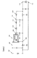
- Figure 8 shows another embodiment of a power supply benefiting from the teachings of the present invention.
- the power supply of Figure 8 is an embodiment of an isolated flyback power supply.
- the voltage across capacitor 810 is related to the voltage across capacitor 812 through the turns ratio of transformer 807 and is therefore a common solution employed to provide feedback to regulate the output of power supplies of the type shown in Figure 8.
- terminal 820 is the input terminal to a voltage regulator circuit, which includes resistors 811 and 818.
- the voltage at the input terminal 820 is representative of the regulated output voltage of the power supply.
- the power supply further includes voltage reference terminal 802, current sense terminal 804 as well as current sense circuitry, one embodiment of which is shown in Figure 4 as circuit 417, which is internal to power supply controller 801 and coupled to current sense terminal 804.
- the power supply controller 400 described in Figure 4 may be utilized for power supply controller 801.
- resistor 818 is coupled between the current sense terminal 804 and voltage reference terminal 802 to provide a second current threshold equal to the sum of the current flowing through resistor 818 and the current threshold of current sense circuitry internal to power supply controller 801, one embodiment of which is shown in figure 4 as circuit 417, coupled to current sense terminal 804.
- the voltage of the current sense terminal 804 substantially fixed relative to the voltage reference terminal 802 when a current equal to the current threshold of the internal current sense circuit flows in the current sense terminal 804.
- the resistor 811 is coupled between the input terminal 820 and current sense terminal 804.
- the input terminal 820 has a voltage threshold relative to the voltage reference terminal 802 that is different from the voltage at the current sense terminal 804 by an amount equal to the product of the value of resistor 811 and the second current threshold.
- Figure 9 shows yet another embodiment of a circuit benefiting from the teachings of the present invention.
- This circuit is similar to that of Figure 8 with the addition of capacitor 919 in parallel to resistor 911.
- This parallel combination forms an effective impedance 921.
- this configuration introduces additional AC coupled feedback to current sense terminal 904, which can further improve circuit stability in some power supply applications.
- resistor 918 coupled between current sense terminal 904 and voltage reference terminal 902 again provides the advantages described above with reference to Figure 8 by reducing the impedance at current sense terminal 904 to reduce noise sensitivity at this terminal and therefore improve power supply stability.
- the addition of capacitor 919 is typically not sufficient alone to provide this improvement and therefore still requires the addition of resistor 918 in accordance with the teachings of the present invention.
Landscapes
- Engineering & Computer Science (AREA)
- Power Engineering (AREA)
- Dc-Dc Converters (AREA)
- Control Of Electrical Variables (AREA)
- Continuous-Control Power Sources That Use Transistors (AREA)
Applications Claiming Priority (2)
| Application Number | Priority Date | Filing Date | Title |
|---|---|---|---|
| US600982 | 2003-06-20 | ||
| US10/600,982 US6833689B1 (en) | 2003-06-20 | 2003-06-20 | Method for reducing the cost of voltage regulation circuitry in switch mode power supplies |
Publications (2)
| Publication Number | Publication Date |
|---|---|
| EP1489729A2 true EP1489729A2 (de) | 2004-12-22 |
| EP1489729A3 EP1489729A3 (de) | 2005-10-05 |
Family
ID=33418579
Family Applications (1)
| Application Number | Title | Priority Date | Filing Date |
|---|---|---|---|
| EP04250736A Withdrawn EP1489729A3 (de) | 2003-06-20 | 2004-02-11 | Verfahren zur Verringerung der Kosten von Spannungsreglerschaltungen in Schaltnetzteilen |
Country Status (3)
| Country | Link |
|---|---|
| US (3) | US6833689B1 (de) |
| EP (1) | EP1489729A3 (de) |
| JP (1) | JP4554243B2 (de) |
Cited By (3)
| Publication number | Priority date | Publication date | Assignee | Title |
|---|---|---|---|---|
| EP1990904A2 (de) * | 2007-01-18 | 2008-11-12 | Samsung SDI Co., Ltd. | Stromversorgungsvorrichtung für Plasmaanzeigegeräte |
| CN104302042A (zh) * | 2014-09-15 | 2015-01-21 | 广东良得光电科技有限公司 | 一种高效率超小功率非隔离led驱动电路 |
| EP1978624A3 (de) * | 2007-04-06 | 2016-08-03 | Power Integrations, Inc. | Verfahren und Vorrichtung für die integrierte Kompensation von Spannungsabfällen an einem Gleichstromsteller angeschlossenen Kabel |
Families Citing this family (14)
| Publication number | Priority date | Publication date | Assignee | Title |
|---|---|---|---|---|
| KR100467594B1 (ko) * | 2002-07-23 | 2005-01-24 | 삼성전자주식회사 | 전자기기 상의 파워 서플라이 제어방법 및 장치 |
| JP3691500B2 (ja) * | 2003-10-29 | 2005-09-07 | 松下電器産業株式会社 | スイッチング電源装置 |
| US7215107B2 (en) * | 2005-07-11 | 2007-05-08 | Power Integrations, Inc. | Method and apparatus to limit output power in a switching power supply |
| US7453710B2 (en) * | 2006-04-26 | 2008-11-18 | Power Integrations, Inc. | Transformerless safety isolation in a power supply using safety capacitors for galvanic isolation |
| EP1903653B1 (de) * | 2006-08-31 | 2018-09-26 | Avago Technologies General IP (Singapore) Pte. Ltd. | Überspannungsschutz für Strom- und Datenanwendungen |
| US7576528B2 (en) * | 2006-10-04 | 2009-08-18 | Power Integrations, Inc. | Control circuit responsive to an impedance |
| DE102008021582B4 (de) | 2008-04-30 | 2014-08-21 | Continental Automotive Gmbh | Verfahren und Vorrichtung zum Betreiben eines Energiespeichers |
| WO2010041183A2 (en) * | 2008-10-10 | 2010-04-15 | Koninklijke Philips Electronics, N.V. | Methods and apparatus for controlling multiple light sources via a single regulator circuit to provide variable color and/or color temperature light |
| JP2011061913A (ja) * | 2009-09-07 | 2011-03-24 | Panasonic Corp | スイッチング電源装置、及びそれに用いる半導体装置 |
| US20110238341A1 (en) * | 2010-03-25 | 2011-09-29 | Mehdi Etezadi-Amoli | High Power DC Kilowatt Hour Meter |
| WO2013085531A1 (en) * | 2011-12-09 | 2013-06-13 | Technicolor Usa, Inc. | An electrostatic discharge protection arrangement |
| US9627967B2 (en) * | 2014-03-21 | 2017-04-18 | Stmicroelectronics International N.V. | Power management system and method of use thereof |
| DE202016104993U1 (de) | 2016-09-09 | 2017-12-12 | Deutsches Zentrum für Luft- und Raumfahrt e.V. | Schaltwandler |
| CN115016585B (zh) * | 2022-06-30 | 2023-11-10 | 天水七四九电子有限公司 | 一种程控直流电源系统 |
Family Cites Families (16)
| Publication number | Priority date | Publication date | Assignee | Title |
|---|---|---|---|---|
| JPH0536485A (ja) * | 1991-07-31 | 1993-02-12 | Iwasaki Electric Co Ltd | 放電灯点灯装置 |
| JP3131364B2 (ja) * | 1994-11-28 | 2001-01-31 | シャープ株式会社 | チョッパ型レギュレータ回路およびチョッパ型レギュレータic |
| JP2835299B2 (ja) * | 1995-07-25 | 1998-12-14 | 東光株式会社 | 自励式dc−dcコンバータ |
| US5777462A (en) * | 1996-08-15 | 1998-07-07 | Hughes Electronics Corporation | Mode configurable DC power supply |
| US5982161A (en) * | 1998-10-14 | 1999-11-09 | Intel Corporation | Voltage regulator having variable frequency-based control |
| US6147883A (en) * | 1998-11-16 | 2000-11-14 | Power Integrations, Inc. | Output feedback and under-voltage detection |
| JP2000193687A (ja) * | 1998-12-25 | 2000-07-14 | Toyota Autom Loom Works Ltd | 電流検出回路、およびその電流検出回路を備えたdc/dcコンバ―タ |
| US6181120B1 (en) * | 1999-09-01 | 2001-01-30 | Intersil Corporation | Current mode dc/dc converter with controlled output impedance |
| US6480399B2 (en) * | 2000-03-02 | 2002-11-12 | Power Integrations, Inc. | Switched mode power supply responsive to current derived from voltage across energy transfer element input |
| US6522108B2 (en) * | 2001-04-13 | 2003-02-18 | Vlt Corporation | Loss and noise reduction in power converters |
| JP4149915B2 (ja) * | 2001-07-05 | 2008-09-17 | ディーアイ/ディーティー, インコーポレーテッド | 絶縁切替え調整器におけるインダクタ電流感知および関連する方法 |
| US6600298B2 (en) * | 2001-10-31 | 2003-07-29 | Dell Products L.P. | Switching DC-DC converter with the output voltage changing inversely to any change in the converter inductor current |
| JP2003189602A (ja) * | 2001-12-17 | 2003-07-04 | Murata Mfg Co Ltd | Dc−dcコンバータおよびそれを用いた電子装置 |
| US6650092B1 (en) * | 2002-05-24 | 2003-11-18 | Motorola, Inc. | System and method for regulating a power system with feedback using current sensing |
| US6686725B1 (en) * | 2002-11-12 | 2004-02-03 | Samsung Electro-Mechanics Co., Ltd. | Power supply circuit compensating power factor |
| US6850044B2 (en) * | 2003-03-13 | 2005-02-01 | Semiconductor Components Industries, L.L.C. | Hybrid regulator with switching and linear sections |
-
2003
- 2003-06-20 US US10/600,982 patent/US6833689B1/en not_active Expired - Lifetime
-
2004
- 2004-02-11 EP EP04250736A patent/EP1489729A3/de not_active Withdrawn
- 2004-03-17 JP JP2004076124A patent/JP4554243B2/ja not_active Expired - Fee Related
- 2004-11-12 US US10/986,622 patent/US7049794B2/en not_active Expired - Lifetime
-
2006
- 2006-01-20 US US11/336,728 patent/US7368894B2/en not_active Expired - Fee Related
Cited By (3)
| Publication number | Priority date | Publication date | Assignee | Title |
|---|---|---|---|---|
| EP1990904A2 (de) * | 2007-01-18 | 2008-11-12 | Samsung SDI Co., Ltd. | Stromversorgungsvorrichtung für Plasmaanzeigegeräte |
| EP1978624A3 (de) * | 2007-04-06 | 2016-08-03 | Power Integrations, Inc. | Verfahren und Vorrichtung für die integrierte Kompensation von Spannungsabfällen an einem Gleichstromsteller angeschlossenen Kabel |
| CN104302042A (zh) * | 2014-09-15 | 2015-01-21 | 广东良得光电科技有限公司 | 一种高效率超小功率非隔离led驱动电路 |
Also Published As
| Publication number | Publication date |
|---|---|
| JP4554243B2 (ja) | 2010-09-29 |
| JP2005012993A (ja) | 2005-01-13 |
| EP1489729A3 (de) | 2005-10-05 |
| US7368894B2 (en) | 2008-05-06 |
| US20040257052A1 (en) | 2004-12-23 |
| US6833689B1 (en) | 2004-12-21 |
| US20050083023A1 (en) | 2005-04-21 |
| US20060119328A1 (en) | 2006-06-08 |
| US7049794B2 (en) | 2006-05-23 |
Similar Documents
| Publication | Publication Date | Title |
|---|---|---|
| US6833689B1 (en) | Method for reducing the cost of voltage regulation circuitry in switch mode power supplies | |
| US7208921B2 (en) | DC-DC regulator with switching frequency responsive to load | |
| US7561452B2 (en) | Transformer-isolated flyback converters and methods for regulating output current thereof | |
| US8310845B2 (en) | Power supply circuit with a control terminal for different functional modes of operation | |
| US9065346B2 (en) | Method and apparatus for integrated cable drop compensation of a power converter | |
| US7999522B2 (en) | Method and apparatus for power conversion and regulation | |
| US7276886B2 (en) | Dual buck-boost converter with single inductor | |
| TW201946351A (zh) | 電源控制用半導體裝置以及開關電源裝置及其設計方法 | |
| US10615700B1 (en) | Synchronous rectifier control for switched mode power supplies and method therefor | |
| US11038423B2 (en) | Frequency control circuit, control method and switching converter | |
| CN212850271U (zh) | 开关模式电源 | |
| US10243464B2 (en) | Power regulator with prevention of inductor current reversal | |
| KR20080086798A (ko) | 고전압 전력 공급 회로용 방법 및 장치 | |
| Qu et al. | A fully soft switched point-of-load converter for resource constraint drone applications | |
| US20250105746A1 (en) | Switching power supply device and power control semiconductor device | |
| US12592639B2 (en) | Self-biasing the input controller in a power converter | |
| RU2779529C2 (ru) | Однотактный обратноходовый импульсный источник питания с изменяемым выходным напряжением | |
| JP2000324814A (ja) | スイッチング電源装置 |
Legal Events
| Date | Code | Title | Description |
|---|---|---|---|
| PUAI | Public reference made under article 153(3) epc to a published international application that has entered the european phase |
Free format text: ORIGINAL CODE: 0009012 |
|
| AK | Designated contracting states |
Kind code of ref document: A2 Designated state(s): AT BE BG CH CY CZ DE DK EE ES FI FR GB GR HU IE IT LI LU MC NL PT RO SE SI SK TR |
|
| AX | Request for extension of the european patent |
Extension state: AL LT LV MK |
|
| PUAL | Search report despatched |
Free format text: ORIGINAL CODE: 0009013 |
|
| AK | Designated contracting states |
Kind code of ref document: A3 Designated state(s): AT BE BG CH CY CZ DE DK EE ES FI FR GB GR HU IE IT LI LU MC NL PT RO SE SI SK TR |
|
| AX | Request for extension of the european patent |
Extension state: AL LT LV MK |
|
| RIC1 | Information provided on ipc code assigned before grant |
Ipc: 7H 02M 3/156 A |
|
| 17P | Request for examination filed |
Effective date: 20060307 |
|
| AKX | Designation fees paid |
Designated state(s): DE FR GB IT NL SE |
|
| RAP3 | Party data changed (applicant data changed or rights of an application transferred) |
Owner name: POWER INTEGRATIONS, INC. |
|
| STAA | Information on the status of an ep patent application or granted ep patent |
Free format text: STATUS: THE APPLICATION IS DEEMED TO BE WITHDRAWN |
|
| 18D | Application deemed to be withdrawn |
Effective date: 20150829 |
|
| R18D | Application deemed to be withdrawn (corrected) |
Effective date: 20150901 |