EP1490565B1 - Systeme de pose de dalles - Google Patents
Systeme de pose de dalles Download PDFInfo
- Publication number
- EP1490565B1 EP1490565B1 EP02779182A EP02779182A EP1490565B1 EP 1490565 B1 EP1490565 B1 EP 1490565B1 EP 02779182 A EP02779182 A EP 02779182A EP 02779182 A EP02779182 A EP 02779182A EP 1490565 B1 EP1490565 B1 EP 1490565B1
- Authority
- EP
- European Patent Office
- Prior art keywords
- paving
- frame
- tile
- profile
- profiles
- Prior art date
- Legal status (The legal status is an assumption and is not a legal conclusion. Google has not performed a legal analysis and makes no representation as to the accuracy of the status listed.)
- Expired - Lifetime
Links
- 238000007789 sealing Methods 0.000 claims abstract description 15
- 230000003014 reinforcing effect Effects 0.000 claims description 9
- 239000004575 stone Substances 0.000 claims description 7
- 239000002131 composite material Substances 0.000 claims description 2
- 238000001746 injection moulding Methods 0.000 claims description 2
- 239000011810 insulating material Substances 0.000 claims 2
- 239000013013 elastic material Substances 0.000 claims 1
- 230000001747 exhibiting effect Effects 0.000 claims 1
- 230000004308 accommodation Effects 0.000 abstract 1
- 239000000853 adhesive Substances 0.000 description 19
- 230000001070 adhesive effect Effects 0.000 description 19
- 238000009413 insulation Methods 0.000 description 19
- 238000009434 installation Methods 0.000 description 10
- 239000000463 material Substances 0.000 description 9
- 229920001971 elastomer Polymers 0.000 description 7
- 239000010438 granite Substances 0.000 description 7
- 238000013459 approach Methods 0.000 description 4
- 238000004873 anchoring Methods 0.000 description 3
- 239000011324 bead Substances 0.000 description 3
- 230000006378 damage Effects 0.000 description 3
- 238000007667 floating Methods 0.000 description 3
- 238000002347 injection Methods 0.000 description 3
- 239000007924 injection Substances 0.000 description 3
- 238000003780 insertion Methods 0.000 description 3
- 230000037431 insertion Effects 0.000 description 3
- 238000005304 joining Methods 0.000 description 3
- 238000000034 method Methods 0.000 description 3
- 239000004033 plastic Substances 0.000 description 3
- 229920003023 plastic Polymers 0.000 description 3
- 229920002725 thermoplastic elastomer Polymers 0.000 description 3
- 239000002023 wood Substances 0.000 description 3
- 230000015572 biosynthetic process Effects 0.000 description 2
- 239000000919 ceramic Substances 0.000 description 2
- 239000011248 coating agent Substances 0.000 description 2
- 238000000576 coating method Methods 0.000 description 2
- 238000013461 design Methods 0.000 description 2
- 239000006260 foam Substances 0.000 description 2
- 239000012943 hotmelt Substances 0.000 description 2
- 230000013011 mating Effects 0.000 description 2
- 239000004814 polyurethane Substances 0.000 description 2
- XLYOFNOQVPJJNP-UHFFFAOYSA-N water Substances O XLYOFNOQVPJJNP-UHFFFAOYSA-N 0.000 description 2
- 239000004793 Polystyrene Substances 0.000 description 1
- 239000004823 Reactive adhesive Substances 0.000 description 1
- 238000004026 adhesive bonding Methods 0.000 description 1
- 238000004140 cleaning Methods 0.000 description 1
- 150000001875 compounds Chemical class 0.000 description 1
- 238000005336 cracking Methods 0.000 description 1
- 238000005520 cutting process Methods 0.000 description 1
- 238000013016 damping Methods 0.000 description 1
- 238000011161 development Methods 0.000 description 1
- 230000018109 developmental process Effects 0.000 description 1
- 230000000694 effects Effects 0.000 description 1
- 238000009408 flooring Methods 0.000 description 1
- 239000012530 fluid Substances 0.000 description 1
- 239000003292 glue Substances 0.000 description 1
- 238000010438 heat treatment Methods 0.000 description 1
- 230000003993 interaction Effects 0.000 description 1
- 230000007774 longterm Effects 0.000 description 1
- 238000004519 manufacturing process Methods 0.000 description 1
- 239000004579 marble Substances 0.000 description 1
- 230000035515 penetration Effects 0.000 description 1
- 230000002093 peripheral effect Effects 0.000 description 1
- 229920002223 polystyrene Polymers 0.000 description 1
- 229920002635 polyurethane Polymers 0.000 description 1
- 230000036316 preload Effects 0.000 description 1
- 238000009418 renovation Methods 0.000 description 1
- 239000007787 solid Substances 0.000 description 1
- 230000003068 static effect Effects 0.000 description 1
- 229910052572 stoneware Inorganic materials 0.000 description 1
- 229920001169 thermoplastic Polymers 0.000 description 1
- 239000004416 thermosoftening plastic Substances 0.000 description 1
- 230000007704 transition Effects 0.000 description 1
Images


Classifications
-
- E—FIXED CONSTRUCTIONS
- E04—BUILDING
- E04F—FINISHING WORK ON BUILDINGS, e.g. STAIRS, FLOORS
- E04F13/00—Coverings or linings, e.g. for walls or ceilings
- E04F13/07—Coverings or linings, e.g. for walls or ceilings composed of covering or lining elements; Sub-structures therefor; Fastening means therefor
- E04F13/08—Coverings or linings, e.g. for walls or ceilings composed of covering or lining elements; Sub-structures therefor; Fastening means therefor composed of a plurality of similar covering or lining elements
- E04F13/0862—Coverings or linings, e.g. for walls or ceilings composed of covering or lining elements; Sub-structures therefor; Fastening means therefor composed of a plurality of similar covering or lining elements composed of a number of elements which are identical or not, e.g. carried by a common web, support plate or grid
-
- E—FIXED CONSTRUCTIONS
- E01—CONSTRUCTION OF ROADS, RAILWAYS, OR BRIDGES
- E01C—CONSTRUCTION OF, OR SURFACES FOR, ROADS, SPORTS GROUNDS, OR THE LIKE; MACHINES OR AUXILIARY TOOLS FOR CONSTRUCTION OR REPAIR
- E01C5/00—Pavings made of prefabricated single units
- E01C5/001—Pavings made of prefabricated single units on prefabricated supporting structures or prefabricated foundation elements except coverings made of layers of similar elements
-
- E—FIXED CONSTRUCTIONS
- E04—BUILDING
- E04F—FINISHING WORK ON BUILDINGS, e.g. STAIRS, FLOORS
- E04F15/00—Flooring
- E04F15/02—Flooring or floor layers composed of a number of similar elements
- E04F15/02005—Construction of joints, e.g. dividing strips
- E04F15/02011—Construction of joints, e.g. dividing strips with joint fillings integrated in the flooring elements
-
- E—FIXED CONSTRUCTIONS
- E04—BUILDING
- E04F—FINISHING WORK ON BUILDINGS, e.g. STAIRS, FLOORS
- E04F15/00—Flooring
- E04F15/02—Flooring or floor layers composed of a number of similar elements
- E04F15/02005—Construction of joints, e.g. dividing strips
- E04F15/02016—Construction of joints, e.g. dividing strips with sealing elements between flooring elements
-
- E—FIXED CONSTRUCTIONS
- E04—BUILDING
- E04F—FINISHING WORK ON BUILDINGS, e.g. STAIRS, FLOORS
- E04F15/00—Flooring
- E04F15/02—Flooring or floor layers composed of a number of similar elements
- E04F15/02172—Floor elements with an anti-skid main surface, other than with grooves
-
- E—FIXED CONSTRUCTIONS
- E04—BUILDING
- E04F—FINISHING WORK ON BUILDINGS, e.g. STAIRS, FLOORS
- E04F15/00—Flooring
- E04F15/02—Flooring or floor layers composed of a number of similar elements
- E04F15/02194—Flooring consisting of a number of elements carried by a non-rollable common support plate or grid
-
- E—FIXED CONSTRUCTIONS
- E04—BUILDING
- E04F—FINISHING WORK ON BUILDINGS, e.g. STAIRS, FLOORS
- E04F15/00—Flooring
- E04F15/02—Flooring or floor layers composed of a number of similar elements
- E04F15/08—Flooring or floor layers composed of a number of similar elements only of stone or stone-like material, e.g. ceramics, concrete; of glass or with a top layer of stone or stone-like material, e.g. ceramics, concrete or glass
- E04F15/082—Flooring or floor layers composed of a number of similar elements only of stone or stone-like material, e.g. ceramics, concrete; of glass or with a top layer of stone or stone-like material, e.g. ceramics, concrete or glass with a top layer of stone or stone-like material, e.g. ceramics, concrete or glass in combination with a lower layer of other material
-
- E—FIXED CONSTRUCTIONS
- E04—BUILDING
- E04F—FINISHING WORK ON BUILDINGS, e.g. STAIRS, FLOORS
- E04F15/00—Flooring
- E04F15/02—Flooring or floor layers composed of a number of similar elements
- E04F15/10—Flooring or floor layers composed of a number of similar elements of other materials, e.g. fibrous or chipped materials, organic plastics, magnesite tiles, hardboard, or with a top layer of other materials
- E04F15/105—Flooring or floor layers composed of a number of similar elements of other materials, e.g. fibrous or chipped materials, organic plastics, magnesite tiles, hardboard, or with a top layer of other materials of organic plastics with or without reinforcements or filling materials
-
- E—FIXED CONSTRUCTIONS
- E04—BUILDING
- E04F—FINISHING WORK ON BUILDINGS, e.g. STAIRS, FLOORS
- E04F15/00—Flooring
- E04F15/18—Separately-laid insulating layers; Other additional insulating measures; Floating floors
- E04F15/20—Separately-laid insulating layers; Other additional insulating measures; Floating floors for sound insulation
- E04F15/203—Separately-laid layers for sound insulation
Definitions
- the invention relates to a support frame for plates, to a bottom plate comprising a plate and this support frame, and to a laying system comprising plates and support frame and is particularly suitable for stoneware tiles and natural stone tiles and wood panels.
- Floor tiles are, as far as it is stone or ceramic tiles, usually by means of a suitable adhesive on the appropriately prepared pad, z. B. on a smooth screed, laid, the joint width is usually determined by inserting joints crosses and the joints must be filled later.
- the laying is comparatively complicated both in terms of the tools required and in terms of the necessary materials and also requires a relatively high level of craftsmanship from the publisher.
- a high amount of time is required until the coating is walkable.
- Another disadvantage is the fact that a laid after this procedure plate coating not readily, d. H. can not be removed without destroying the plates.
- edges of floor and wall panels to be laid in each case with an edge profile, which may be glued to the plates.
- the edge profile are formed so that a first leg for the support of the plate and a second leg for abutment against the peripheral edge surface of the plate is present.
- a projection is still provided on the side facing away from the plate on the plate edge extending leg, which is responsible for a predetermined minimum width of the joint together with the projection of the adjacent plate.
- a cover profile is used in the joint. This cover profile is secured by a tooth against slipping out.
- a non-slip damping layer may be provided, however, the edge region of the underside of the plate is released because there are circumferentially applied the edge profiles.
- the pre-assembled with the edge profiles plates are designed on a bottom surface so that the projections abut each other.
- the frame has an upper and a lower side.
- the upper side contains flooring material.
- the engaging elements are designed and arranged to connect adjacent side edges of opposite sex.
- the frame is provided with a plurality of openings extending between the upper and lower sides.
- the floor covering material is adhesively secured through the openings with a cushioning foam pad located on the lower side.
- the floor covering material is fastened to the upper side of the frame by latching elements located on the upper side of the extensions.
- the engaging elements of opposite sex which are located on the lower side of the extensions, serve to connect adjacent floor panels. They work together in a vertical direction.
- the invention has for its object to provide a laying system in which the laying of the plates relatively easily, d. H. can also be performed by untrained persons.
- the installation system should be suitable in particular for natural stone slabs such as granite, marble, etc. but also for wood, ceramic or other materials produced panels. It should also ensure that the pad can be removed if necessary without damaging the individual plates.
- the invention consists of a support frame or from a base plate or from a laying system, with the features of claim 7 or 6 or 1.
- each plate is at least partially with its underside on one of the support profiles having bearing areas bearing frame, wherein the support frame has a bearing on the support surface to the top of the plate projecting approach, which extends at least partially along the edge of the plate towards the top of the plate ,
- the support frame can be connected to each other.
- the approach is a part of the support frame and is provided only on two adjacent support profiles, whereas the other two support profiles have a support area without approach.
- the first support profiles have at least one latching extension beyond the plate in the lateral direction, wherein the two another, second support profiles have at least one lying below the plate in the lateral direction Rastforsatz and cooperates in each case one support profile with another support profile in the lateral direction.
- expansion joints are no longer necessary even when laying larger areas, as there is no solid contact to the ground by the floating installation.
- no glue is needed for the installation.
- the support frame are provided on its underside with a footfall sound insulation.
- the subject of the application is a base plate comprising a plate and a support frame for use in a laying system.
- Another object is a support frame for a plate.
- a floor covering which consists of a plurality of each other lined stone slabs, z. B. granite plates, is formed, the interposition of my distance joint on a base, z. B. a raw screed or a floor board floating.
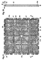
- FIG. 1 shows, in a diagrammatic illustration, a quadrangular frame 1 for receiving a plate (not shown in this figure), e.g. B. a granite plate.
- the frame 1 is made of a plastic and is prefabricated; it may consist of a one-piece molded part or of individual elements which are composed of a bar profile. As a material, a recycled plastic can be used.
- legs 1a to 1d of the frame 1 have in each case a leg 1c, 1d which adjoins one another, a plug-in profile 3 which is shown in cross-section in FIG.
- the two other legs 1a, 1b have a male profile 4 as shown in Fig. 5 in cross section.
- All four legs 1a to 1d have a strip-shaped support 5, on which in the installed state a usable in the frame plate 2 rests.
- Fig. 2a the support of such a plate 2 is shown on the strip-shaped support 5 with the male profile 4.
- the width of the support 5 is expediently 20 mm at a plate width of 305 mm.
- the predetermined by the strength (height) of the support 5 of the frame 1 distance from the laying mat (floor screed) to the patch plate 2 can be advantageously used to insert a footfall sound insulation 12.
- the height of the impact sound insulation 12 is to be dimensioned so that it corresponds to the said distance from the laying pad to plate only in the loaded state.
- the impact sound insulation 12 is advantageously glued to the underside of the plate.
- Fig. 2b the installation state of two plates is shown, but the right of the illustrated plates 2 is offset for illustrative purposes to the rear.
- the plate 2 lies with its underside in the edge region on the strip-shaped support 5 and is glued thereto.
- the footfall sound insulation 12 extends not only to the vicinity of the support 5, but also under this, so that even in the area of the support 5 takes place insulation. This is shown with broken lines, wherein the area below the support 5 is designated by the reference numeral 13.
- the male profile 3 of the legs 1c and 1d a vertically upwardly directed projection 6, abut the plates 2 on the two sides in the installed state.
- the projection 6 is provided with a groove 7, in which a shown in Fig. 6 in cross-section rubber seal 8 is inserted. If required, the seal 8 can be glued in the groove area with the neck 6 of the leg, so that a working out is reliably avoided.
- the seal 8 adapted in one of the color scheme of the plates Color produce. It is therefore not necessary that the frame is color matched to the plates.
- the rubber seal 8 is mushroom-shaped, wherein the stem 8a of the seal 8 is formed so that it fits into the groove 7 of the projection 6.
- the hat 8b is preferably trapezoidal and designed in height so that its upper edge in the installed state terminates approximately with the upper edge of a plate inserted into the frame 2, as shown in Fig. 2b.
- the width of the rubber seal 8 is dimensioned larger at least towards the upper end than the width of the projection 6, whereby in the installed state of the plates, the rubber seal is pressed together and a gap seal is achieved.
- the rubber seal 8 is mitred at an angle of 90 ° (FIG. 3), so that a seal is also achieved at the point of intersection.
- the plug-in profile 3 (FIG. 4) contains an extension 9, which corresponds to a mating detent groove 11 in the plug-in profile 4 (FIG. 5).
- the two plug-in profiles 3 and 4 thus form a snap-in lock with which several frames can easily be put together and later easily separated again. So that a problem-free mating of the parts is achieved without cutting on site, the extensions 9 are reset with the locking cam 10 with respect to the outer edge of the frame by a degree X at each frame.
- Each plate 2 to be laid is provided with a frame as shown in FIG.
- the frames are glued to the underside of the plates so that the plate and frame form a unit.
- the gluing also has the advantage that the plates firmly fixed in the plate composite are and a "working out" of the plates is avoided even with long-term committing the finished covering.
- a further latching connection is shown in which the legs 1c superior locking cam 10 provides on its upper side and on its underside undercuts, which engage in a likewise two undercuts having groove 11 on the receiving leg 1a.
- the locking cam Upon penetration of the locking cam in the locking groove, this is spread open and snaps together after the complete insertion and the system of the side edge of the leg 1a at the side edge and the neck 6 of the leg 1c again.
- the material elasticity is selected so that this is possible without destruction.
- Fig. 8 the locking connection in the region of a projection 14 and a groove 15 itself formed undercuts, so that only one guide takes place here.
- the mechanical securing takes place via a locking cam 10 on the underside of the projection 14 and a latching recess 11 In the surface of the lower side wall of the groove 11.
- an insertion 16 may be provided for ease of assembly, which is indicated by dashed lines.
- a support frame 21 consists here in addition to the marginal edge profiles 21a, b, c, d of stiffening ribs 22, 23, of which a first group 22 is parallel to the sides and a second group 23 in the diagonal direction.
- the ribs 22, 23 intersect, so that crossing points 24 arise. These crossing points can be of different sizes.
- edge profiles 21a to d upper and lower projections 25, 26 are formed, which each represent one half of a latching connection, namely the upper half and the lower half. This will be explained in more detail below.
- Each rib of the edge profiles 21a-d and 22, 23 limited field support area 27 has openings, indicated by the puncture, whose function will be explained later.
- FIG. 10 shows a cross section through the support frame according to FIG. 9, wherein the side profiles 21b, 21d can be seen in the edge region.
- the course of the web 28 can be seen.
- the web 28 extends from the profiles 21a to d over almost the entire length or width of the support frame 21, but only on two adjacent sides. This can be seen in FIG. 9 by means of the web 28 arranged on the profile 21a and the web 29 arranged on the adjacent profile 21b.
- Fig. 10 the openings 30 and the inner ribs 22 are also shown. To recognize are further an upper and lower part 25, 26 of a locking connection.
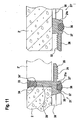
- Fig. 11 the left side is shown as section AA of Fig. 9, the right side of Fig. 11 corresponds to a neighboring plate according to the invention. Shown is initially the frame profile 21 with the edge profile 21a, on which a plate 2 rests and is thereby determined by acting as a stop web 28 in position.
- the support frame 21 is provided with openings 30, which will be explained later.
- an upper projection 25 is shown, which has a downwardly directed latching teeth 31.
- the transition region protrusion 25 in the frame profile 21a is elastically resilient, so that the projection 25 has a certain flexibility.
- a bottom plate adjacent thereto is provided, the edge structure of which corresponds to the section BB of FIG. 9.
- the plate 2 ' thus engages over the lower projection 26, so that when joining the bottom plates 21, 21', the plate 2 'comes to rest above the upper projection 25 of the edge profile 21a.
- this installation situation for the plate 2 ' is shown, in which case the lower projection 26 of the support profile 21c is below the upper projection 25 of the frame profile 21a.
- the upper projection 25 is thus enclosed on both sides. So that the upper latching projection 25 can nevertheless slide over the latching teeth, is a Distance to the plate 2 'provided so that the top of the locking projection 25 is lower than the bottom of the plate 2' and the bearing surface of the plate. 2
- the plates 2, 2 ' are held by the web 28 at a predetermined minimum distance from each other, wherein a mounted on the web 28 seal 33 seal the plates from the top.
- the seal 33 is widened wedge-shaped upward and has in the region of the shaft on to the plate 2 and 2 'extending sealing lip 34, 34' on.
- the wedge-shaped end of the seal 33 comes with the inclined surfaces for contact with correspondingly formed inclined surfaces on the plates 2, 2 'and thereby causes a seal.
- moisture such as an applied cleaning fluid
- the support frame is also provided on its underside with a receiving groove 35 in which an insulating profile 36 is inserted.
- the insulating profile 36 projects beyond the lower edge of the frame profile 21a and can have lateral compensation spaces 37, 37 'which allow deformation of the insulating profile 36 under load.
- the support profiles 21a and the stiffening ribs 22, 23 are provided with an embedded in a groove insulation profile, so that there is a good impact sound insulation.
- FIG. 12 also shows a section along the line AA, but here the arrangement of the opening 30, 30 'and the interposed support webs 38 of the support region 27 can be seen. Of particular importance is the course of the side walls of the webs 38 such that the opening 30 of the support surface for the plate to the bottom of the support frame 21 out to expand. This allows the mechanical anchoring of the plate in the support frame 21 by means of passing through the opening 30 adhesive.
- the plate, not shown, is thereby also mechanically firmly connected to the support frame 21, since a kind of dovetail connection is formed.
- the adhesive application on the upper side of the support web 38 takes place, for example, mechanically by means of a doctor blade.
- only the back of the plate may be coated with adhesive, or both. It is not always necessary to bring about a full-surface bonding. In some cases, it is sufficient to coat only partial surfaces with adhesive, wherein the adhesive may also be applied in the form of a bead of adhesive.
- thermoplastic adhesives so-called hot melts may be used, but also one- or multi-component reactive adhesives, in particular polyurethane (PU) adhesive with a slight AnFum .
- PU polyurethane
- the upper and the lower projections 25, 26 can be seen, wherein the projections 25, 26 on the support profile 21a, however, are not opposite, but are offset in the plane of the drawing by a distance, as shown in FIG is. However, here the interaction of the ratchet teeth can be seen well. It should be noted that the lower projection 26 has an elasticity to allow a sliding past the locking teeth. An additional alternative space is not provided here, since it is assumed is that the entire plate when loosening the locking connection can also be raised. Thus, a release of the latching connection is possible even if the upper latching projection would be supported directly on the underside of the plate.
- FIG. 13 shows a section of the lower right-hand corner from FIG. 9.
- Both the support profiles 21a, 21d and the reinforcing ribs 22, 23 have an insulating profile 36th which can be sharpened via a central injection point 40 in the region of the intersection point 24 into the grooves 35 provided after the support frame has been produced in a first injection process.
- the bearing surface between the edge profile 21a and the reinforcing rib 23 is provided with apertures 30, 30 ', between which the support webs 38 extend.
- Fig. 14a is again a section through the support profile 21a, 21d shown, which in turn can be seen that only the edge profile 21a is provided with the web 28, which acts as a stop for the plate, whereas the support profile 21d has no such web ,
- a particular embodiment of the seal 33 is shown.
- sealing beads 34 are provided, which project into a groove on the edge of the plate 2, 2 '.
- the groove 41 can certainly also be larger than the sealing bead 34, as long as it is ensured that at least in sections a seal is made. There is thus a sealing surface 42 available.
- connection of the plate to the support frame is produced for example by means of an adhesive technique.
- hot melt or a curable adhesive can be applied so that the adhesive passes through the conically widening openings 30 and causes a mechanical anchoring.
- a normal adhesive bond is present, so that the plate is fixed after curing of the adhesive both via the adhesive bond and on the mechanical anchoring in the manner of a dovetail connection.
- the support frame may be provided with the thermoplastic elastomer by a two-component injection molding process and the impact sound insulation seal 33 with a hard-plastic material, such as the frame itself.
- a hard-plastic material such as the frame itself.
- Polystyrene or polyurethane comes into question and as impact sound insulation a thermoplastic elastomer TPE.
- the locking teeth can also be using a single projection simply latching or as in the exemplary embodiment as a detent toothing multiple detent, so that optionally reinforceddifferenzen be compensated.
- the locking connection is designed so that when lifting the plate at the opposite edge due to the leverage
- the one-sided locking connection of the second embodiment has the advantage that the overall height compared to a connector is again significantly reduced.
- the impact sound insulation is embedded in the bearing surface, in the embodiment in the reinforcing ribs 22, 23 and the edge profiles 21a to d. This also makes it possible to achieve a low height.
- the footfall sound insulation can be designed so that in addition a slip-resistant effect is achieved.
- the bottom plate formed of plate and support frame has due to the adhesive joint increased static strength, so that the required plate thickness in the case of granite plates from previously 10 mm to 8 mm or even up to 6 mm thickness is possible. This leads to a considerable material and thus cost savings in the production of a floor covering.
- the insulating profile 36 projects beyond the underside of the edge profiles 21a-d or the reinforcing ribs 22, 23, but the underside of the support profiles or reinforcing ribs also come to rest under extreme load and thus prevent destruction of the impact sound insulation.
- the embedded in a groove impact sound insulation is therefore protected against damage under extreme load.
- the adhesive itself should be chosen so that sufficient thermal stability is achieved when using underfloor heating. When laying outdoors, the adhesive must be weather-resistant.
Landscapes
- Engineering & Computer Science (AREA)
- Architecture (AREA)
- Civil Engineering (AREA)
- Structural Engineering (AREA)
- Ceramic Engineering (AREA)
- Chemical & Material Sciences (AREA)
- Floor Finish (AREA)
- Road Paving Structures (AREA)
- Steam Or Hot-Water Central Heating Systems (AREA)
- Conveying And Assembling Of Building Elements In Situ (AREA)
Claims (15)
- Système de pose, comprenant des dalles (2) et un cadre de pose (21), pour la réalisation d'un revêtement de sol en dalles, en particulier en carrelage de pierre, chaque dalle (2) reposant au moins partiellement par sa face inférieure sur le cadre de pose (21) comportant des profilés de bord (21a, 21b, 21c, 21d) avec des zones d'appui, le cadre de pose (21) comportant une traverse (28) dépassant de la surface de pose vers la face supérieure de la dalle, laquelle s'étend au moins partiellement le long du bord de la dalle (2) vers la face supérieure de la dalle (2), et les cadres de pose (21) étant assemblables entre eux, caractérisé en ce que la traverse (28) est un composant du cadre de pose (21), en ce que la traverse (28) n'est prévue que sur deux profilés de pose (21a, 21b) adjacents l'un à l'autre, les deux autres profilés de pose (21 c, 21d) présentant en revanche une zone de pose sans traverse, les premiers profilés (21a, 21b) présentant au moins une saillie d'enclenchement (25, 26) dépassant sur la dalle (2) dans une direction latérale, les deux autres profilés de pose (21c, 21d) comportant au moins une saillie d'enclenchement (25, 26) disposée sous la dalle (2) dans une direction latérale, et chaque profilé de pose (21 a, 21 b) coopérant avec un autre profilé de pose (21 c, 21 d) en direction latérale.
- Système de pose selon la revendication 1, caractérisé en ce qu'un profilé de joint (28) est formé sur l'épaulement, et s'étend le long du bord de la dalle (2) vers la face supérieure de la dalle (2).
- Système de pose selon la revendication 1 ou la revendication 2, caractérisé en ce que le cadre de pose (21) et la dalle (2) forment une unité et sont préférentiellement collés entre eux.
- Système de pose selon l'une des revendications 1 à 3, caractérisé en ce que le cadre de pose (21) est muni d'une isolation de bruit de pas (36) sur sa face inférieure.
- Système de pose selon la revendication 4, caractérisé en ce que le cadre de pose présente une isolation de bruit de pas (36) sous la zone de pose.
- Dalle de sol, comprenant une dalle (2) et un cadre de pose (21), selon l'une des revendications 7 à 15.
- Cadre de pose (21) pour des dalles (2) à utiliser dans un système de pose, comportant des profilés de bord (21a, 21a, 21c, 21d) avec des zones d'appui pour les dalles (2), une traverse (28) dépassant de la surface de pose vers la face supérieure de la dalle, laquelle s'étend au moins partiellement le long du bord de la dalle (2) vers la face supérieure de la dalle (2), et les cadres de pose (21) étant assemblables entre eux, caractérisé en ce que la traverse (28) est un composant du cadre de pose (21), en ce que la traverse (28) n'est prévue que sur deux profilés de pose (21a, 21b) adjacents l'un à l'autre, les deux autres profilés de pose (21c, 21d) présentant en revanche une zone de pose sans traverse, les premiers profilés (21a, 21b) présentant au moins une saillie d'enclenchement (25, 26) dépassant sur la dalle (2) dans une direction latérale, les deux autres profilés de pose (21c, 21d) comportant au moins une saillie d'enclenchement (25, 26) disposée sous la dalle (2) dans une direction latérale, et chaque profilé de pose (21a, 21b) coopérant avec un autre profilé de pose (21c, 21d) en direction latérale.
- Cadre de pose (21) selon la revendication 7, caractérisé en ce qu'un joint (8) fixé sur la traverse (28) est prévu, en particulier dans un matériau caoutchouteux élastique.
- Cadre de pose (21) selon la revendication 7 ou la revendication 8, caractérisé par une rainure (7) ménagée dans l'épaulement (6), dans laquelle le joint (8) est insérable.
- Cadre de pose (21) selon l'une des revendications 7 à 9, caractérisé en ce que le cadre de pose est pourvu d'un profilé isolant (36) sur sa face inférieure, ledit profilé isolant (36) étant notamment logé dans une rainure (35).
- Cadre de pose (21) selon l'une des revendications 7 à 10, caractérisé en ce que le cadre de pose (21) présente des nervures de renforcement (22, 23) et une surface de pose (27) avec des traversées (30, 30'), et en ce que les nervures de renforcement (22, 23) sont pourvues d'une rainure (35) pour le logement d'un profilé isolant (36) sur leur face inférieure.
- Cadre de pose (21) selon la revendication 11, caractérisé en ce que les traversées (30, 30') de la surface de pose s'élargissent en cônes à partir de la dalle.
- Cadre de pose (21) selon l'une des revendications 7 à 12, caractérisé en ce que le cadre de pose (21) est préfabriqué en une seule pièce.
- Cadre de pose (21) selon l'une des revendications 7 à 12, caractérisé en ce que le cadre de pose (21) se compose de profilés (21a - d) assemblés, de préférence des profilés filés.
- Cadre de pose (21) selon la revendication 8 ou 10 ainsi que l'une des revendications 9 ou 11 à 14, caractérisé en ce que le joint (8) d'une part et le profilé isolant (36) d'autre part sont matériellement raccordés au cadre, en particulier par injection directe.
Applications Claiming Priority (5)
| Application Number | Priority Date | Filing Date | Title |
|---|---|---|---|
| DE10158215 | 2001-11-28 | ||
| DE10158215A DE10158215B4 (de) | 2001-11-28 | 2001-11-28 | Verlegesystem für Bodenplatten |
| DE20214622U DE20214622U1 (de) | 2001-11-28 | 2002-09-20 | Verlegesystem für Bodenplatten |
| DE20214622U | 2002-09-20 | ||
| PCT/DE2002/004023 WO2003040491A1 (fr) | 2001-11-28 | 2002-10-28 | Systeme de pose de dalles |
Publications (2)
| Publication Number | Publication Date |
|---|---|
| EP1490565A1 EP1490565A1 (fr) | 2004-12-29 |
| EP1490565B1 true EP1490565B1 (fr) | 2007-09-26 |
Family
ID=26010668
Family Applications (1)
| Application Number | Title | Priority Date | Filing Date |
|---|---|---|---|
| EP02779182A Expired - Lifetime EP1490565B1 (fr) | 2001-11-28 | 2002-10-28 | Systeme de pose de dalles |
Country Status (9)
| Country | Link |
|---|---|
| US (1) | US7197855B2 (fr) |
| EP (1) | EP1490565B1 (fr) |
| CN (1) | CN1309920C (fr) |
| AT (1) | ATE374294T1 (fr) |
| AU (1) | AU2002342548A1 (fr) |
| DE (2) | DE10295140D2 (fr) |
| ES (1) | ES2246746T1 (fr) |
| RU (1) | RU2305164C2 (fr) |
| WO (1) | WO2003040491A1 (fr) |
Families Citing this family (109)
| Publication number | Priority date | Publication date | Assignee | Title |
|---|---|---|---|---|
| GB0202310D0 (en) * | 2002-02-01 | 2002-03-20 | Kingspan Access Floors Ltd | Improvements in and relating to floor panels |
| DE502004009090D1 (de) * | 2003-07-07 | 2009-04-16 | Poschacher Natursteinwerke Gmb | Platte zur verlegung auf böden, wänden, decken, fassaden oder dgl |
| US7181891B2 (en) * | 2003-09-08 | 2007-02-27 | Quiet Solution, Inc. | Acoustical sound proofing material and methods for manufacturing same |
| AT414147B (de) * | 2003-10-01 | 2006-09-15 | Lenhard Backhaus Hugo Dipl Ing | Belag aus belagsplatten |
| AT414253B (de) * | 2003-10-01 | 2006-10-15 | Lenhard Backhaus Hugo Dipl Ing | Bodenbelag aus belagsplatten |
| DE10355788B4 (de) * | 2003-11-26 | 2008-02-07 | Meyer, Hans | Platte zur Verwendung in einem Verlegesystem, insbesondere zur Herstellung eines Bodenbelags sowie Verfahren zur Herstellung derselben |
| WO2005071185A1 (fr) * | 2004-01-27 | 2005-08-04 | Sispel Suministro E Instalaciones, S.L. | Revetement modulaire enregistrable pour surfaces de revetement |
| WO2006042883A2 (fr) * | 2004-08-20 | 2006-04-27 | Azulindus Y Marti, S.A. | Revetement demontable pour surfaces |
| US8495851B2 (en) * | 2004-09-10 | 2013-07-30 | Serious Energy, Inc. | Acoustical sound proofing material and methods for manufacturing same |
| ATE481537T1 (de) | 2004-10-05 | 2010-10-15 | Nicolaas Albertus Heyns | Trägerelement, modulares fliesenelement, system von verriegelungsmechanismen und verfahren zum verlegen von fliesen |
| US7921965B1 (en) | 2004-10-27 | 2011-04-12 | Serious Materials, Inc. | Soundproof assembly and methods for manufacturing same |
| US7610731B1 (en) * | 2005-01-10 | 2009-11-03 | Comc, Llc | Snap together floor structure |
| US7798287B1 (en) * | 2005-01-20 | 2010-09-21 | Serious Materials, Inc. | Acoustical ceiling panels |
| ES2259544B1 (es) | 2005-02-07 | 2007-09-16 | Taulell, S.A. | Suelo desmontable. |
| US7743568B1 (en) * | 2005-02-25 | 2010-06-29 | Montgomery Mars | Tile system and method |
| DE102005019638B4 (de) | 2005-04-26 | 2007-02-08 | Kronotec Ag | Verfahren zur Herstellung eines Fußbodenelementes |
| EP1934417B1 (fr) | 2005-10-03 | 2012-05-23 | Tarkett SAS | Kit de construction de revêtement de surface |
| US7543417B2 (en) * | 2005-10-04 | 2009-06-09 | Comc, Llc | Modular flooring assemblies |
| CN101313114B (zh) * | 2005-10-04 | 2013-10-02 | Comc有限责任公司 | 模块化地板组件 |
| AU2011250780B2 (en) * | 2005-10-04 | 2014-07-10 | Comc, Llc | Modular flooring assemblies |
| US8029881B2 (en) * | 2005-11-04 | 2011-10-04 | Serious Energy, Inc. | Radio frequency wave reducing material and methods for manufacturing same |
| US20070227094A1 (en) * | 2006-03-14 | 2007-10-04 | Larach Oscar | Modular raintank |
| ES1062734Y (es) * | 2006-04-17 | 2006-10-16 | Golden Decking S L | Placa perfeccionada para la configuracion de suelos |
| DE102006024857A1 (de) * | 2006-05-24 | 2007-11-29 | Guido Schulte | Belag für Böden, Wände oder Decken |
| US20080078135A1 (en) * | 2006-10-03 | 2008-04-03 | Mcintosh Jonathan | Grout member for modular flooring assemblies |
| CA2669203A1 (fr) * | 2006-11-20 | 2008-05-29 | Gruppo Concorde S.P.A. | Systeme et procede de pose a sec d'elements de revetement pour planchers ou murs, et support dudit systeme |
| US20080171179A1 (en) * | 2007-01-11 | 2008-07-17 | Quiet Solution, Llc | Low embodied energy wallboards and methods of making same |
| EP1953308A1 (fr) * | 2007-01-31 | 2008-08-06 | Sika Technology AG | Procédé destiné à l'application d'un revêtement de sol sur un sol |
| US7984600B2 (en) | 2007-02-02 | 2011-07-26 | Mohawk Carpet Corporation | Groutless tile system and method for making the same |
| US20120090258A1 (en) * | 2007-02-02 | 2012-04-19 | Mohawk Carpet Corporation | Groutless tile system and method for making the same |
| WO2008109961A1 (fr) * | 2007-03-15 | 2008-09-18 | Innvotech Pty Ltd | Appareil de revêtement de carreaux |
| US7987645B2 (en) * | 2007-03-29 | 2011-08-02 | Serious Materials, Inc. | Noise isolating underlayment |
| SG146580A1 (en) * | 2007-03-29 | 2008-10-30 | Promociones Brial S L | Assembly system for floor and/or wall tiles |
| US9388568B2 (en) | 2007-04-06 | 2016-07-12 | Pacific Coast Building Products, Inc. | Acoustical sound proofing material with improved fracture characteristics and methods for manufacturing same |
| US7883763B2 (en) | 2007-04-12 | 2011-02-08 | Serious Materials, Inc. | Acoustical sound proofing material with controlled water-vapor permeability and methods for manufacturing same |
| US8424251B2 (en) * | 2007-04-12 | 2013-04-23 | Serious Energy, Inc. | Sound Proofing material with improved damping and structural integrity |
| US8181738B2 (en) * | 2007-04-24 | 2012-05-22 | Serious Energy, Inc. | Acoustical sound proofing material with improved damping at select frequencies and methods for manufacturing same |
| US8397864B2 (en) * | 2007-04-24 | 2013-03-19 | Serious Energy, Inc. | Acoustical sound proofing material with improved fire resistance and methods for manufacturing same |
| US10174499B1 (en) | 2007-05-01 | 2019-01-08 | Pacific Coast Building Products, Inc. | Acoustical sound proofing material for architectural retrofit applications and methods for manufacturing same |
| US20080286609A1 (en) * | 2007-05-15 | 2008-11-20 | Surace Kevin J | Low embodied energy wallboards and methods of making same |
| US20100101457A1 (en) * | 2007-05-25 | 2010-04-29 | Surace Kevin J | Low embodied energy sheathing panels and methods of making same |
| US20080302053A1 (en) * | 2007-06-08 | 2008-12-11 | Kelly Gibson | Panelling system formed from panels defined by tongue and groove strips |
| US20080302043A1 (en) * | 2007-06-08 | 2008-12-11 | Kelly Gibson | Panelling system formed from rectangular panels |
| US20090000245A1 (en) * | 2007-06-28 | 2009-01-01 | Tinianov Brandon D | Methods of manufacturing acoustical sound proofing material |
| US9387649B2 (en) * | 2007-06-28 | 2016-07-12 | Pacific Coast Building Products, Inc. | Methods of manufacturing acoustical sound proofing materials with optimized fracture characteristics |
| US7908818B2 (en) * | 2008-05-08 | 2011-03-22 | Serious Materials, Inc. | Methods of manufacturing acoustical sound proofing materials with optimized fracture characteristics |
| US7914914B2 (en) * | 2007-06-30 | 2011-03-29 | Serious Materials, Inc. | Low embodied energy sheathing panels with optimal water vapor permeance and methods of making same |
| US7799410B2 (en) * | 2007-06-30 | 2010-09-21 | Serious Materials, Inc. | Acoustical sound proofing material with improved damping at select frequencies and methods for manufacturing same |
| US7707792B2 (en) * | 2007-08-06 | 2010-05-04 | Premark Rwp Holdings, Inc. | Flooring system with grout line |
| US8337993B2 (en) | 2007-11-16 | 2012-12-25 | Serious Energy, Inc. | Low embodied energy wallboards and methods of making same |
| ES1066639Y (es) * | 2007-11-21 | 2008-05-16 | Alaves Montajes Y Realizacione | Loseta para recubrimiento de superficies |
| US20090133348A1 (en) * | 2007-11-22 | 2009-05-28 | Kelly Gibson | Flooring system |
| GB2459460A (en) * | 2008-04-23 | 2009-10-28 | Andrew Nicholas Perla | Prefabricated patio panels |
| KR101050399B1 (ko) * | 2008-05-20 | 2011-07-19 | 현대산업개발 주식회사 | 복수의 방수시트를 이용한 방수공법 |
| WO2010012116A1 (fr) * | 2008-07-29 | 2010-02-04 | Giesbrecht + Partner Ag | Système de revêtement de surface |
| ITVI20080204A1 (it) * | 2008-08-29 | 2010-02-28 | Foster Allestimenti S R L | Pedana di supporto perfezionata per la realizzazione di strutture architettoniche |
| CN101440659A (zh) * | 2008-10-31 | 2009-05-27 | 赖英光 | 一种新型塑料地垫 |
| US8230654B2 (en) | 2009-06-10 | 2012-07-31 | Comc, Llc | Medallion insert for modular flooring assemblies |
| US8782989B2 (en) | 2009-06-11 | 2014-07-22 | Comc, Llc | Narrow lined modular flooring assemblies |
| NL2003559C2 (nl) * | 2009-09-28 | 2011-03-29 | Easy Sanitairy Solutions Bv | Afdichting. |
| KR101316300B1 (ko) | 2009-11-24 | 2013-10-08 | (주)엘지하우시스 | 복합패널 및 그 제조 방법 |
| PT2339092T (pt) * | 2009-12-22 | 2019-07-19 | Flooring Ind Ltd Sarl | Método para produzir painéis de cobertura |
| PL2369090T3 (pl) * | 2010-03-16 | 2016-04-29 | Fligo Flooring Innovation Group Ab | Modułowe podłoże podłogowe |
| BE1019501A5 (nl) | 2010-05-10 | 2012-08-07 | Flooring Ind Ltd Sarl | Vloerpaneel en werkwijze voor het vervaardigen van vloerpanelen. |
| US8925275B2 (en) | 2010-05-10 | 2015-01-06 | Flooring Industries Limited, Sarl | Floor panel |
| BE1019331A5 (nl) | 2010-05-10 | 2012-06-05 | Flooring Ind Ltd Sarl | Vloerpaneel en werkwijzen voor het vervaardigen van vloerpanelen. |
| DE102010017189A1 (de) * | 2010-06-01 | 2011-12-01 | Novo-Tech Gmbh & Co. Kg | Unterkonstruktionselement für einen Bodenbelag |
| WO2012017098A1 (fr) * | 2010-08-05 | 2012-02-09 | Butech Building Technology, S.A. | Procédé de fabrication de pièces pour la formation de revêtements démontables pour sols |
| IT1403088B1 (it) * | 2010-11-10 | 2013-10-04 | Tenax Spa | Elemento per pavimentazione in materiale plastico a struttura reticolare, procedimento per la produzione dello stesso ed uso dell elemento di pavimentazione |
| IT1403352B1 (it) * | 2010-12-23 | 2013-10-17 | Newfloor S R L | Pavimentazione flottante autoposante a secco |
| DE102011004893A1 (de) | 2011-03-01 | 2012-09-06 | Hans Meyer | Verbundplatte, Verbindungsstück und Verlegesystem sowie Verfahren zur Herstellung einer Verbundplatte |
| ITMI20111053A1 (it) * | 2011-06-10 | 2012-12-11 | Planium S R L | Piastra per pavimentazione e metodo per ottenerla |
| ITMI20111052A1 (it) * | 2011-06-10 | 2012-12-11 | Planium S R L | Sistema di pavimentazione |
| KR20130059247A (ko) * | 2011-11-28 | 2013-06-05 | 유니손 코포레이션 | 블록 |
| US8887462B2 (en) * | 2012-08-21 | 2014-11-18 | Ali TATARI | Prefabricated tile system with modular backing board |
| US20140144092A1 (en) * | 2012-11-27 | 2014-05-29 | John G. Benz | System and apparatus for installation of tile floor |
| ITTV20130006A1 (it) * | 2013-01-18 | 2014-07-19 | New Tile Di Girotto Ambra | Struttura di piastrella componibile |
| CA2842448C (fr) | 2013-03-08 | 2016-01-19 | Pavestone, LLC | Pave porteur et procede d'installation |
| EP2989269B1 (fr) * | 2013-04-24 | 2020-10-07 | MXF Holding GmbH | Dalle de plancher, en particulier pour planchers |
| TWM459265U (zh) * | 2013-04-25 | 2013-08-11 | zhe-an Cai | 石材高架地板 |
| US20140373479A1 (en) | 2013-06-21 | 2014-12-25 | Pavestone, LLC | Adjustable locator retaining wall block and mold apparatus |
| USD791346S1 (en) | 2015-10-21 | 2017-07-04 | Pavestone, LLC | Interlocking paver |
| US10583588B2 (en) | 2013-06-21 | 2020-03-10 | Pavestone, LLC | Manufactured retaining wall block with improved false joint |
| CA2924510A1 (fr) | 2013-09-16 | 2015-03-19 | Connor Sports Flooring, Llc | Surface de plancher integrant une base plastique a emboitement |
| USD737468S1 (en) | 2014-05-07 | 2015-08-25 | Pavestone, LLC | Front face of a retaining wall block |
| US9637871B2 (en) * | 2014-06-18 | 2017-05-02 | Newpark Mats & Integrated Services Llc | Load-supporting surface with actively connected gap seals and related apparatus and methods |
| US9809982B2 (en) | 2014-09-15 | 2017-11-07 | Connor Sport Court International, Llc | Suspended modular flooring panel |
| US10012341B2 (en) * | 2015-08-06 | 2018-07-03 | Lined Products Llc | Universal precast base system |
| US10781595B2 (en) | 2015-09-10 | 2020-09-22 | Comc, Llc | Modular flooring assemblies |
| ITUB20154618A1 (it) * | 2015-10-12 | 2017-04-12 | Dps Floor S R L | Attrezzatura modulare per pavimentazioni in legno. |
| EP3483356A4 (fr) * | 2016-07-06 | 2020-02-26 | Huang, Lizhuo | Unité de plancher assemblée et plaque inférieure de celle-ci |
| CA2988547C (fr) | 2016-12-15 | 2021-01-26 | Certainteed Gypsum, Inc. | Panneaux de platre et leurs methodes de fabrication |
| USD854711S1 (en) | 2017-04-05 | 2019-07-23 | Oshkosh Floor Designs Acquisition, LLC | Modular flooring tile |
| US11124965B2 (en) | 2017-09-26 | 2021-09-21 | Certainteed Gypsum, Inc. | Plaster boards having internal layers and methods for making them |
| WO2019067994A1 (fr) | 2017-09-28 | 2019-04-04 | Certainteed Gypsum, Inc. | Plaques de plâtre et leurs procédés de fabrication |
| US11214962B2 (en) | 2017-09-30 | 2022-01-04 | Certainteed Gypsum, Inc. | Tapered plasterboards and methods for making them |
| DE102018000253A1 (de) * | 2018-01-15 | 2019-07-18 | Dieter Preissing | Belagplatte, insbesondere zur Verwendung als Bodenbelag oder als Wandverkleidung |
| KR101907111B1 (ko) * | 2018-02-14 | 2018-10-11 | 이경준 | 레벨 조절 및 충격 흡수가 가능한 우드블럭 모듈 |
| NL2025283B1 (en) * | 2020-04-06 | 2021-10-25 | I4F Licensing Nv | Tile panel, surface covering of a multitude of such tile panels for a floor, ceiling or wall surface. |
| DE202020103699U1 (de) * | 2020-06-26 | 2021-09-28 | Schlüter-Systems Kg | Dehnungsfugenprofilsystem |
| CN111997238B (zh) * | 2020-08-28 | 2021-08-24 | 中冶建工集团有限公司 | 一种干挂面板安装结构 |
| CN112609602A (zh) * | 2020-12-03 | 2021-04-06 | 济南华锐铁路机械制造有限公司 | 一种高铁站台防滑地面铺装结构及其铺装方法 |
| DE202021100478U1 (de) | 2021-02-01 | 2022-05-03 | Schlüter-Systems Kg | Profilsystem |
| CZ2021144A3 (cs) * | 2021-03-23 | 2022-05-25 | Novotek Limited | Podlahová dlaždice |
| NL2028247B1 (en) * | 2021-05-19 | 2022-12-06 | J Van Klinken Holding B V | Interlockable wall reinforcement panel, wall reinforcement assembly and method for wall reinforcement |
| US11840847B2 (en) * | 2021-05-27 | 2023-12-12 | Robert N. PERRINE | Interconnected modular frames for groutless setting of hard tiles |
| NL2028782B1 (en) * | 2021-07-19 | 2023-01-25 | Jan Benninga Sievert | Method of laying a modular surface covering system and underlayment tile |
| USD1037491S1 (en) | 2021-12-14 | 2024-07-30 | Pavestone, LLC | Wall block |
| PL449414A1 (pl) | 2024-07-30 | 2026-02-02 | Mariusz Maciej Bruliński | Podkładka pod płyty budowlane |
Citations (1)
| Publication number | Priority date | Publication date | Assignee | Title |
|---|---|---|---|---|
| WO1999041814A1 (fr) * | 1998-02-13 | 1999-08-19 | Interface, Inc. | Systemes et procedes de pose de revetements de sol modulaires |
Family Cites Families (40)
| Publication number | Priority date | Publication date | Assignee | Title |
|---|---|---|---|---|
| US464850A (en) * | 1891-12-08 | Hydrocarbon-burner | ||
| US2303745A (en) | 1939-02-21 | 1942-12-01 | M B Farrin Lumber Co | Manufacture of single matted flooring panel |
| US3016316A (en) | 1958-12-22 | 1962-01-09 | Arnold P Olson | Laminated board construction |
| US3339329A (en) * | 1965-05-18 | 1967-09-05 | Edward T Berg | Arrangement for securing panels to the surface of a roof or wall |
| US3553921A (en) | 1967-07-04 | 1971-01-12 | Rasmus Breistein | Wall construction, particularly for load-bearing walls |
| US3504472A (en) * | 1967-09-12 | 1970-04-07 | Andrew B Clement | Portable patio floor structure |
| US3535844A (en) | 1969-10-30 | 1970-10-27 | Glaros Products Inc | Structural panels |
| US3723233A (en) | 1971-07-15 | 1973-03-27 | P Bourke | Marble faced wall panels and method of making same |
| DE2246778A1 (de) | 1972-09-23 | 1974-03-28 | Otto Kreibaum | Holzpflaster |
| US4067155A (en) * | 1975-08-28 | 1978-01-10 | Grefco, Inc. | Sealing system |
| SU896216A1 (ru) * | 1980-04-18 | 1982-01-07 | за витель (St) СПОСОБ УСТРОЙСТВА МОЗАИЧНОГО ПОКРЫТИЯ Г.В. Мил х | Способ устройства мозаичного покрыти |
| DE3036339A1 (de) | 1980-09-26 | 1982-05-27 | Villeroy & Boch Keramische Werke Kg, 6642 Mettlach | Verfahren zum verlegen von belagtafeln aus durch vorverfugung miteinander verbundenen fliesen sowie wand- oder bodentafel |
| CA1191304A (fr) * | 1983-02-23 | 1985-08-06 | Richard A. Morrison | Tapis couvre-sol modulaire a lisiere d'assemblage |
| US4640850A (en) | 1983-04-18 | 1987-02-03 | Technomarmi Maiera S.P.A. | Composite slab incorporating a sheet of marble or similar natural stone, for the formation of facings for building, interior decoration and the like |
| US4590731A (en) * | 1983-08-10 | 1986-05-27 | Degooyer Lonnie C | Tile reinforcing grid |
| US4550543A (en) * | 1984-01-09 | 1985-11-05 | Marcello Valenzano | Construction forms |
| JPS6153958A (ja) * | 1984-08-20 | 1986-03-18 | 株式会社 サアミ | タイル状繊維床材敷設方法 |
| US4664955A (en) | 1986-03-21 | 1987-05-12 | Swiss Aluminium Ltd. | Natural stone facing composite laminate |
| GB8612355D0 (en) | 1986-05-21 | 1986-06-25 | Aristodimou E | Stone tiles |
| DE3681920D1 (de) * | 1986-08-20 | 1991-11-14 | William Alan Lonie | Elementeboeden. |
| US4931331A (en) | 1988-04-05 | 1990-06-05 | Owens Charles R | Laminated tile product, method for producing the same and method for installing the same |
| US5418036A (en) * | 1991-11-25 | 1995-05-23 | Fukuyi Chemical Industry Co., Ltd. | Tile application backing material and tile application execution method |
| US5417020A (en) * | 1992-08-12 | 1995-05-23 | Dobija; Michael J. | Wall system providing an array of individual panels |
| FR2721053B1 (fr) * | 1994-06-10 | 1996-08-02 | Fabrication Diffusion | Installation de pose de panneaux sans fixation visible, notamment pour l'habillage de murs et/ou la mise en place d'étagères ou d'équipements suspendus et outil pour la mise en place d'une telle installation. |
| ES2196076T3 (es) * | 1994-09-22 | 2003-12-16 | Johannes Muller-Hartburg | Baldosa y procedimiento para su fabricacion. |
| US5611185A (en) * | 1995-04-19 | 1997-03-18 | Thomas B. Van Wyk | Surface mounted grid system and process of installation |
| US6230385B1 (en) * | 1996-11-01 | 2001-05-15 | Premark Rwp Holdings, Inc. | Molding affixed with wedged divider track |
| US5899040A (en) | 1997-09-08 | 1999-05-04 | Cerrato; Dominic | Flexible interlocking wall system |
| US6694689B1 (en) * | 1998-02-13 | 2004-02-24 | Interface, Inc. | Modular flooring systems and methods |
| US6247286B1 (en) | 1998-08-03 | 2001-06-19 | Nicolaas Albertus Heyns | Modular structural element |
| US6021615A (en) | 1998-11-19 | 2000-02-08 | Brown; Arthur J. | Wood flooring panel |
| TW407667U (en) * | 1999-11-25 | 2000-10-01 | Chen Shing Sheng | Bonding structure of boards supporting bracket |
| DE19962812A1 (de) | 1999-12-23 | 2001-06-28 | Norton Sipro Gmbh | Verfahren und Vorrichtung zum Schließen von Fugen |
| AU4743800A (en) | 1999-12-23 | 2001-07-09 | Hamberger Industriewerke Gmbh | Joint |
| US6332733B1 (en) | 1999-12-23 | 2001-12-25 | Hamberger Industriewerke Gmbh | Joint |
| DE20009717U1 (de) * | 2000-05-30 | 2000-11-16 | Mehlhose Hans Dietrich | Fugenprofil |
| CN2439490Y (zh) * | 2000-06-28 | 2001-07-18 | 陈义钊 | 插接式活动地板撑架 |
| US6647684B1 (en) * | 2001-11-05 | 2003-11-18 | High Mountain Flooring, Inc. | Flooring system |
| US6862855B1 (en) * | 2003-04-16 | 2005-03-08 | Dave G. Milum | Structural assembly for decks, walkways, patios, and docks |
| US6990777B2 (en) * | 2003-04-29 | 2006-01-31 | Jiri Poliacek | Tile installation system |
-
2002
- 2002-10-28 DE DE10295140T patent/DE10295140D2/de not_active Expired - Lifetime
- 2002-10-28 AT AT02779182T patent/ATE374294T1/de active
- 2002-10-28 AU AU2002342548A patent/AU2002342548A1/en not_active Abandoned
- 2002-10-28 RU RU2004120069/03A patent/RU2305164C2/ru not_active IP Right Cessation
- 2002-10-28 CN CNB028276264A patent/CN1309920C/zh not_active Expired - Fee Related
- 2002-10-28 WO PCT/DE2002/004023 patent/WO2003040491A1/fr not_active Ceased
- 2002-10-28 DE DE50210994T patent/DE50210994D1/de not_active Expired - Lifetime
- 2002-10-28 ES ES02779182T patent/ES2246746T1/es active Pending
- 2002-10-28 EP EP02779182A patent/EP1490565B1/fr not_active Expired - Lifetime
-
2004
- 2004-01-08 US US10/752,591 patent/US7197855B2/en not_active Expired - Lifetime
Patent Citations (1)
| Publication number | Priority date | Publication date | Assignee | Title |
|---|---|---|---|---|
| WO1999041814A1 (fr) * | 1998-02-13 | 1999-08-19 | Interface, Inc. | Systemes et procedes de pose de revetements de sol modulaires |
Also Published As
| Publication number | Publication date |
|---|---|
| EP1490565A1 (fr) | 2004-12-29 |
| DE10295140D2 (de) | 2004-12-23 |
| ES2246746T1 (es) | 2006-03-01 |
| DE50210994D1 (de) | 2007-11-08 |
| ATE374294T1 (de) | 2007-10-15 |
| AU2002342548A1 (en) | 2003-05-19 |
| RU2004120069A (ru) | 2005-06-27 |
| US7197855B2 (en) | 2007-04-03 |
| RU2305164C2 (ru) | 2007-08-27 |
| US20040139679A1 (en) | 2004-07-22 |
| CN1309920C (zh) | 2007-04-11 |
| WO2003040491A1 (fr) | 2003-05-15 |
| CN1617966A (zh) | 2005-05-18 |
| HK1078115A1 (en) | 2006-03-03 |
Similar Documents
| Publication | Publication Date | Title |
|---|---|---|
| EP1490565B1 (fr) | Systeme de pose de dalles | |
| DE69434094T2 (de) | Holz- oder Laminatfussbodensystem mit einer Vielzahl von Fussbodenpaneelen | |
| DE60015949T2 (de) | BAUSATZ FüR SCHWIMMENDEN FUSSBODEN | |
| EP2078801B1 (fr) | Dispositif de verrouillage de deux panneaux de construction | |
| DE10158215B4 (de) | Verlegesystem für Bodenplatten | |
| WO2007016978A1 (fr) | Profile de dilatation affleurant | |
| EP0828037A2 (fr) | Profilé de bordure pour balcons ou terrasses recouverts par des carreaux | |
| DE202020103699U1 (de) | Dehnungsfugenprofilsystem | |
| EP2425755B1 (fr) | Tablette de douche | |
| EP2845965B1 (fr) | Fixation d'un madrier sur une infrastructure | |
| DE20107338U1 (de) | Flexibles Bodenbelagsträgersystem | |
| EP1851400A1 (fr) | Profile d'etancheite destine a combler les joints entre des plaques de revetement | |
| DE202008002361U1 (de) | Plattenbelag zur Anordnung an einer Wand, einer Decke oder einem Boden | |
| WO2007137316A1 (fr) | Plancher de bois | |
| DE10311894B4 (de) | Belag, bestehend aus einzelnen Platten aus mineralischem Material | |
| DE102007054173A1 (de) | Plattenkörper für Bauzwecke | |
| DE29823681U1 (de) | Bodenbelag | |
| DE20206984U1 (de) | Kernsockelleiste | |
| DE102008003117A1 (de) | Einrichtung zum Verriegeln zweier Bauplatten | |
| DE10055354B4 (de) | Plattenelement | |
| DE10347199A1 (de) | Beheizbares Fußbodenelement mit Oberflächenschicht | |
| WO2012017060A2 (fr) | Sol plan élastique et module de montage | |
| DE20215223U1 (de) | Fußboden aus einzelnen Elementen | |
| DE10302961B4 (de) | Wandabschlussleiste | |
| DE20005249U1 (de) | Fliesensystem zum wiederaufnehmbaren Verlegen von Fliesen |
Legal Events
| Date | Code | Title | Description |
|---|---|---|---|
| PUAI | Public reference made under article 153(3) epc to a published international application that has entered the european phase |
Free format text: ORIGINAL CODE: 0009012 |
|
| 17P | Request for examination filed |
Effective date: 20040707 |
|
| AK | Designated contracting states |
Kind code of ref document: A1 Designated state(s): AT BE BG CH CY CZ DE DK EE ES FI FR GB GR IE IT LI LU MC NL PT SE SK TR |
|
| AX | Request for extension of the european patent |
Extension state: AL LT LV MK RO SI |
|
| 17Q | First examination report despatched |
Effective date: 20051104 |
|
| GRAP | Despatch of communication of intention to grant a patent |
Free format text: ORIGINAL CODE: EPIDOSNIGR1 |
|
| GRAS | Grant fee paid |
Free format text: ORIGINAL CODE: EPIDOSNIGR3 |
|
| GRAA | (expected) grant |
Free format text: ORIGINAL CODE: 0009210 |
|
| AK | Designated contracting states |
Kind code of ref document: B1 Designated state(s): AT BE BG CH CY CZ DE DK EE ES FI FR GB GR IE IT LI LU MC NL PT SE SK TR |
|
| REG | Reference to a national code |
Ref country code: GB Ref legal event code: FG4D Free format text: NOT ENGLISH |
|
| REG | Reference to a national code |
Ref country code: CH Ref legal event code: EP |
|
| REF | Corresponds to: |
Ref document number: 50210994 Country of ref document: DE Date of ref document: 20071108 Kind code of ref document: P |
|
| REG | Reference to a national code |
Ref country code: IE Ref legal event code: FG4D Free format text: LANGUAGE OF EP DOCUMENT: GERMAN |
|
| PG25 | Lapsed in a contracting state [announced via postgrant information from national office to epo] |
Ref country code: FI Free format text: LAPSE BECAUSE OF FAILURE TO SUBMIT A TRANSLATION OF THE DESCRIPTION OR TO PAY THE FEE WITHIN THE PRESCRIBED TIME-LIMIT Effective date: 20070926 |
|
| NLV1 | Nl: lapsed or annulled due to failure to fulfill the requirements of art. 29p and 29m of the patents act | ||
| GBV | Gb: ep patent (uk) treated as always having been void in accordance with gb section 77(7)/1977 [no translation filed] | ||
| BERE | Be: lapsed |
Owner name: MEYER, HANS Effective date: 20071031 |
|
| PG25 | Lapsed in a contracting state [announced via postgrant information from national office to epo] |
Ref country code: NL Free format text: LAPSE BECAUSE OF FAILURE TO SUBMIT A TRANSLATION OF THE DESCRIPTION OR TO PAY THE FEE WITHIN THE PRESCRIBED TIME-LIMIT Effective date: 20070926 Ref country code: ES Free format text: LAPSE BECAUSE OF FAILURE TO SUBMIT A TRANSLATION OF THE DESCRIPTION OR TO PAY THE FEE WITHIN THE PRESCRIBED TIME-LIMIT Effective date: 20080106 Ref country code: GR Free format text: LAPSE BECAUSE OF FAILURE TO SUBMIT A TRANSLATION OF THE DESCRIPTION OR TO PAY THE FEE WITHIN THE PRESCRIBED TIME-LIMIT Effective date: 20071227 |
|
| REG | Reference to a national code |
Ref country code: IE Ref legal event code: FD4D |
|
| PG25 | Lapsed in a contracting state [announced via postgrant information from national office to epo] |
Ref country code: PT Free format text: LAPSE BECAUSE OF FAILURE TO SUBMIT A TRANSLATION OF THE DESCRIPTION OR TO PAY THE FEE WITHIN THE PRESCRIBED TIME-LIMIT Effective date: 20080226 Ref country code: SK Free format text: LAPSE BECAUSE OF FAILURE TO SUBMIT A TRANSLATION OF THE DESCRIPTION OR TO PAY THE FEE WITHIN THE PRESCRIBED TIME-LIMIT Effective date: 20070926 Ref country code: CZ Free format text: LAPSE BECAUSE OF FAILURE TO SUBMIT A TRANSLATION OF THE DESCRIPTION OR TO PAY THE FEE WITHIN THE PRESCRIBED TIME-LIMIT Effective date: 20070926 Ref country code: MC Free format text: LAPSE BECAUSE OF NON-PAYMENT OF DUE FEES Effective date: 20071031 |
|
| PG25 | Lapsed in a contracting state [announced via postgrant information from national office to epo] |
Ref country code: SE Free format text: LAPSE BECAUSE OF FAILURE TO SUBMIT A TRANSLATION OF THE DESCRIPTION OR TO PAY THE FEE WITHIN THE PRESCRIBED TIME-LIMIT Effective date: 20071226 |
|
| EN | Fr: translation not filed | ||
| PG25 | Lapsed in a contracting state [announced via postgrant information from national office to epo] |
Ref country code: DK Free format text: LAPSE BECAUSE OF FAILURE TO SUBMIT A TRANSLATION OF THE DESCRIPTION OR TO PAY THE FEE WITHIN THE PRESCRIBED TIME-LIMIT Effective date: 20070926 |
|
| PLBE | No opposition filed within time limit |
Free format text: ORIGINAL CODE: 0009261 |
|
| STAA | Information on the status of an ep patent application or granted ep patent |
Free format text: STATUS: NO OPPOSITION FILED WITHIN TIME LIMIT |
|
| 26N | No opposition filed |
Effective date: 20080627 |
|
| PG25 | Lapsed in a contracting state [announced via postgrant information from national office to epo] |
Ref country code: BE Free format text: LAPSE BECAUSE OF NON-PAYMENT OF DUE FEES Effective date: 20071031 |
|
| PG25 | Lapsed in a contracting state [announced via postgrant information from national office to epo] |
Ref country code: FR Free format text: LAPSE BECAUSE OF FAILURE TO SUBMIT A TRANSLATION OF THE DESCRIPTION OR TO PAY THE FEE WITHIN THE PRESCRIBED TIME-LIMIT Effective date: 20080704 Ref country code: IE Free format text: LAPSE BECAUSE OF FAILURE TO SUBMIT A TRANSLATION OF THE DESCRIPTION OR TO PAY THE FEE WITHIN THE PRESCRIBED TIME-LIMIT Effective date: 20070926 |
|
| PG25 | Lapsed in a contracting state [announced via postgrant information from national office to epo] |
Ref country code: GB Free format text: LAPSE BECAUSE OF FAILURE TO SUBMIT A TRANSLATION OF THE DESCRIPTION OR TO PAY THE FEE WITHIN THE PRESCRIBED TIME-LIMIT Effective date: 20070926 |
|
| PG25 | Lapsed in a contracting state [announced via postgrant information from national office to epo] |
Ref country code: EE Free format text: LAPSE BECAUSE OF FAILURE TO SUBMIT A TRANSLATION OF THE DESCRIPTION OR TO PAY THE FEE WITHIN THE PRESCRIBED TIME-LIMIT Effective date: 20070926 |
|
| PG25 | Lapsed in a contracting state [announced via postgrant information from national office to epo] |
Ref country code: CY Free format text: LAPSE BECAUSE OF FAILURE TO SUBMIT A TRANSLATION OF THE DESCRIPTION OR TO PAY THE FEE WITHIN THE PRESCRIBED TIME-LIMIT Effective date: 20070926 |
|
| PG25 | Lapsed in a contracting state [announced via postgrant information from national office to epo] |
Ref country code: BG Free format text: LAPSE BECAUSE OF FAILURE TO SUBMIT A TRANSLATION OF THE DESCRIPTION OR TO PAY THE FEE WITHIN THE PRESCRIBED TIME-LIMIT Effective date: 20071226 Ref country code: LU Free format text: LAPSE BECAUSE OF NON-PAYMENT OF DUE FEES Effective date: 20071028 |
|
| PG25 | Lapsed in a contracting state [announced via postgrant information from national office to epo] |
Ref country code: TR Free format text: LAPSE BECAUSE OF FAILURE TO SUBMIT A TRANSLATION OF THE DESCRIPTION OR TO PAY THE FEE WITHIN THE PRESCRIBED TIME-LIMIT Effective date: 20070926 |
|
| REG | Reference to a national code |
Ref country code: CH Ref legal event code: NV Representative=s name: FREI PATENTANWALTSBUERO AG Ref country code: CH Ref legal event code: PUE Owner name: NFS NEW FLOORING SYSTEMS AG Free format text: MEYER, HANS#RHEINFELDSTRASSE 57#68063 LUDWIGSHAFEN (DE) -TRANSFER TO- NFS NEW FLOORING SYSTEMS AG#HELVETIASTRASSE 51#3005 BERN (CH) |
|
| PG25 | Lapsed in a contracting state [announced via postgrant information from national office to epo] |
Ref country code: IT Free format text: LAPSE BECAUSE OF NON-PAYMENT OF DUE FEES Effective date: 20071031 |
|
| REG | Reference to a national code |
Ref country code: DE Ref legal event code: R081 Ref document number: 50210994 Country of ref document: DE Owner name: CLICK'N WALK AG, CH Free format text: FORMER OWNER: MEYER, HANS, 67063 LUDWIGSHAFEN, DE Effective date: 20110216 |
|
| REG | Reference to a national code |
Ref country code: CH Ref legal event code: PUE Owner name: CLICK'N WALK AG Free format text: NFS NEW FLOORING SYSTEMS AG#HELVETIASTRASSE 51#3005 BERN (CH) -TRANSFER TO- CLICK'N WALK AG#HELVETIASTRASSE 51#3005 BERN (CH) |
|
| REG | Reference to a national code |
Ref country code: DE Ref legal event code: R082 Ref document number: 50210994 Country of ref document: DE Representative=s name: OSTERTAG & PARTNER, PATENTANWAELTE, DE Effective date: 20120906 Ref country code: DE Ref legal event code: R082 Ref document number: 50210994 Country of ref document: DE Representative=s name: OSTERTAG & PARTNER PATENTANWAELTE, DE Effective date: 20120906 Ref country code: DE Ref legal event code: R082 Ref document number: 50210994 Country of ref document: DE Representative=s name: OSTERTAG & PARTNER, PATENTANWAELTE MBB, DE Effective date: 20120906 Ref country code: DE Ref legal event code: R081 Ref document number: 50210994 Country of ref document: DE Owner name: CLICK'N WALK AG, CH Free format text: FORMER OWNER: NFS NEW FLOORING SYSTEMS AG, BERN, CH Effective date: 20120906 |
|
| REG | Reference to a national code |
Ref country code: AT Ref legal event code: HC Ref document number: 374294 Country of ref document: AT Kind code of ref document: T Owner name: CLICK'N WALK AG, CH Effective date: 20121003 |
|
| PGFP | Annual fee paid to national office [announced via postgrant information from national office to epo] |
Ref country code: DE Payment date: 20151022 Year of fee payment: 14 Ref country code: CH Payment date: 20151007 Year of fee payment: 14 |
|
| PGFP | Annual fee paid to national office [announced via postgrant information from national office to epo] |
Ref country code: AT Payment date: 20151022 Year of fee payment: 14 |
|
| REG | Reference to a national code |
Ref country code: DE Ref legal event code: R119 Ref document number: 50210994 Country of ref document: DE |
|
| REG | Reference to a national code |
Ref country code: CH Ref legal event code: PL |
|
| REG | Reference to a national code |
Ref country code: AT Ref legal event code: MM01 Ref document number: 374294 Country of ref document: AT Kind code of ref document: T Effective date: 20161028 |
|
| PG25 | Lapsed in a contracting state [announced via postgrant information from national office to epo] |
Ref country code: DE Free format text: LAPSE BECAUSE OF NON-PAYMENT OF DUE FEES Effective date: 20170503 Ref country code: CH Free format text: LAPSE BECAUSE OF NON-PAYMENT OF DUE FEES Effective date: 20161031 Ref country code: LI Free format text: LAPSE BECAUSE OF NON-PAYMENT OF DUE FEES Effective date: 20161031 |
|
| PG25 | Lapsed in a contracting state [announced via postgrant information from national office to epo] |
Ref country code: AT Free format text: LAPSE BECAUSE OF NON-PAYMENT OF DUE FEES Effective date: 20161028 |