EP1490600B1 - Centrifugal pump with reverse rotation protection integrated on the impeller blade - Google Patents
Centrifugal pump with reverse rotation protection integrated on the impeller blade Download PDFInfo
- Publication number
- EP1490600B1 EP1490600B1 EP03715361A EP03715361A EP1490600B1 EP 1490600 B1 EP1490600 B1 EP 1490600B1 EP 03715361 A EP03715361 A EP 03715361A EP 03715361 A EP03715361 A EP 03715361A EP 1490600 B1 EP1490600 B1 EP 1490600B1
- Authority
- EP
- European Patent Office
- Prior art keywords
- centrifugal
- impeller
- centrifugal pump
- pump
- cylindrical
- Prior art date
- Legal status (The legal status is an assumption and is not a legal conclusion. Google has not performed a legal analysis and makes no representation as to the accuracy of the status listed.)
- Expired - Lifetime
Links
- 239000007788 liquid Substances 0.000 claims abstract description 47
- 230000001360 synchronised effect Effects 0.000 claims description 8
- 230000001105 regulatory effect Effects 0.000 claims description 6
- 238000010276 construction Methods 0.000 description 4
- 230000033001 locomotion Effects 0.000 description 4
- XLYOFNOQVPJJNP-UHFFFAOYSA-N water Substances O XLYOFNOQVPJJNP-UHFFFAOYSA-N 0.000 description 4
- 241000950314 Figura Species 0.000 description 1
- 230000000694 effects Effects 0.000 description 1
- 230000005389 magnetism Effects 0.000 description 1
- 238000004519 manufacturing process Methods 0.000 description 1
- 239000000463 material Substances 0.000 description 1
- 238000000034 method Methods 0.000 description 1
- 230000004048 modification Effects 0.000 description 1
- 238000012986 modification Methods 0.000 description 1
- 230000000630 rising effect Effects 0.000 description 1
- 230000000007 visual effect Effects 0.000 description 1
Images

Classifications
-
- F—MECHANICAL ENGINEERING; LIGHTING; HEATING; WEAPONS; BLASTING
- F04—POSITIVE - DISPLACEMENT MACHINES FOR LIQUIDS; PUMPS FOR LIQUIDS OR ELASTIC FLUIDS
- F04D—NON-POSITIVE-DISPLACEMENT PUMPS
- F04D15/00—Control, e.g. regulation, of pumps, pumping installations or systems
- F04D15/0077—Safety measures
Definitions
- the present invention relates to a centrifugal pump for liquids with an impeller having curved blades, used for example in aquariums, in the food industry, in fountains and the like.
- the pumps of this type comprise a centrifugal impeller made of a hub from which a plurality of blades having a curved shape extend.
- the centrifugal impeller is coupled to an electric synchronous motor contained inside a motor casing which is sealed in order to prevent water from entering inside, thus damaging the motor.
- the electric synchronous motor comprises a stator made of an electromagnet and a rotor formed by a permanent magnet which is integrally and axially coupled to the centrifugal pump.
- the centrifugal pump is housed inside an impeller casing which has a cylindrical shape defined by a cylindrical wall and two circular side walls: a first circular side wall wherein a suction intake for the liquid to be pumped is made in the axial position and a second circular side wall defined by the motor casing. An outlet for the liquid is made in the cylindrical wall.
- the impellers with curved blades are uni-directional, that is they have a predetermined rotating direction for a correct functioning, unlike impellers with straight and radial blades which are bi-directional. In fact, the latter have a symmetrical-axial impeller and, then, the rotating direction has no effect on the functioning of the pump.
- centrifugal pumps are coupled to an electric synchronous motor which, as it is known, may start indifferently in one direction or in the opposite direction. Therefore, it is evident that, in case of impellers having curved blades, there are good chances that the pump begins to rotate in the wrong direction, thus preventing the pump from functioning or even starting.
- impellers with straight blades are used.
- these impellers have a low efficiency.
- Another aspect to be considered is due to the fact that such solutions may reduce me proper functioning of the pump, so causing losses of the liquid to be pumped and then to diminuish the total efficiency of the same, that in pumps so small is already low.
- the dimensions of electro-pumps is an important characteristic, if not the main one.
- EP 1 074 744 discloses a centrifugal pump with tabs on the backside of the shroud which interact with a uni-directional stopping means in the pump casing.
- the aim of the present invention is to construct a centrifugal pump with curved baldes in which the efficiency is significantly increased with respect to those of the prior art.
- centrifugal impeller is smaller with respect to those of the prior art having the same performance, but it also requires an electric motor with reduced power and then with inferior dimension.
- the electro-pump has restricted dimension if compared with the dimension of other electro-pumps of the same type and performance, so as to be advantageously used for example in aquariums and fountains, where the overall dimension of the product represents the main characteristic in choosing the product.
- This aim is reached by a centrifugal pump for liquids according to claim 1.
- the impeller is able to direct the liquid in an optimum way, the turbulent and whirling motions are significantly reduced and, then, the hydraulic losses, which are responsible for the most part of the dissipation of the energy given to the liquid, are remarkably reduced.
- the present centrifugal impeller is made with reduced dimensions if compared with pumps of the prior art of the same performance and, since it requires less power, smaller electric motors are used, therefore the entire electro-pump is compact.
- the construction of this impeller does not involve difficulties, since it can be constructed with the same processes used to build the impellers of the prior art, and without introducing further constrution phases.
- the centrifugal pump comprises adjusting means for the liquid flow in order to regulate the amount of liquid which comes out from said outlet, means which comprise a cylindrical tang rotatably mounted inside said cylindrical wall of said impeller chamber, said cylindrical tang having at least one opening so that when said cylindrical tang or said cylindrical wall rotate, the supply liquid is regulated from a maximum value when the opening of said cylindrical tang is positioned at the outlet made in said cylindrical wall, to a zero value when the cylindrical tang completely closes the outlet.
- an electro-pump for liquids preferably water, which is used for example in aquariums, fountains, in food industries, or in other fields, is entirely indicated with reference 8.
- the electro-pump 8 comprises a centrifugal pump 10 coupled to an electric synchronous motor 30 contained inside a motor casing 20.
- the motor casing 20 is a box-like element which contains inside the electric motor 30 in a sealed water manner in order to prevent water from going inside.
- the synchronous electric motor 30 comprises a stator (not visible in figures) made up of an electro-magnet which works as an inductor and a rotor 32 made up of a permanent magnet which works as an armature.
- the centrifugal pump 10 comprises a centrifugal impeller 40 contained in an impeller chamber or volute 50.
- the centrifugal pump 40 comprises a hub 42 on which a plurality of blades 44 with a curved profile are fixed.
- the motor or the permanent magnet 32 is axially and securely coupled to the hub 32 of the centrifugal impeller 40.
- the impeller chamber 50 comprises a cover 60 and a cylindrical wall 52 delimited by a first circular edge 52a and a second circular edge 52b.
- the cylindrical wall 52 is rotatably mounted on the motor casing 20 by fixing the first circular edge 52a to a circular wall 22 made on the motor casing 20.
- the cover 60 is rotatably mounted on the cylindrical wall 52 at the second circular edge 52b.
- An essentially circular opening 24 is made on the circular wall 22 of the motor casing 20, from which the hub 42 of the centrifugal impeller comes out.
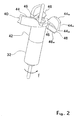
- centrifugal impeller 40 as better represented in figure 2 , it can be noted that three identical blades 44 with a curved profile are fixed to the hub 42. Each blade 44 is defined by two curved and parallel edges 44a,44b which extend from the hub 42 and by an end edge 44c. A radial tab 46 extends from the curved edge 44a of each blade 44 and on the side of the concavity of the blades 44.
- the radial tab 46 has an end edge which joins the hub 32 with the free end of the curved profile 44a and from which a tab 48 extends out folded in the opposite direction with respect to the blade.
- the free end 48a of the folded tabs 48 is close to the circular wall 22 of the motor casing 20, so that during the rotation of the centrifugal impeller 40, the free edge 48a passes very near to the circular wall 22.
- a uni-directional stopping element 26 is made on the circular wall 22 and interacts with the folded tabs 48.
- the uni-directional stopping element 26 consists of a projecting element delimited, from one side, by a profile which gradually rises with respect to the circular wall 22 and, on the opposite side, by a profile essentially right-angled with respect to the circular wall 22, so that as the centrifugal impeller 40 rotates in the direction indicated by the arrow F of figure 2 , namely when the free edge 48a of the folded tabs 48 interacts with the gradually rising profile of the stopping element 26, the centrifugal impeller 40 is free to rotate, whereas a rotation in the opposite direction is prevented since the free edge 48a of the folded tabs interacts with the right-angled profile of the stopping element 26.
- the centrifugal impeller 40 may only rotate in the direction of the arrow F, that is with the convex profile which presses on the liquid and then in the correct direction of its functioning.
- the assembly of the rotor 32 and the centrifugal impeller 40 are mounted on the electro-pump 8 with a prefixed axial gap, so that slight axial movements with respect to the impeller chamber 50 may occur to the centrifugal impeller 40, as well as to the rotor 32 inside the motor casing 20.
- the centrifugal impeller 40 moves slightly away from the circular wall 22 of the motor casing 20, so as to avoid any contact between the folded tabs 48 and the uni-directional stopping element 26. Therefore, the mechanical losses due to the continuous contact between the folded tabs 48 with the circular wall 22 are eliminated.
- an opening 54 is made in the cylindrical wall 52 which represents the outlet for the liquid and is connected to a cylindrical duct 56.
- a hole 62 is made in the central position of the cover 60, so as to form the suction intake of the liquid.
- a cup 64 is mounted on the cover 60 which covers the hole 62 and, then, the suction intake, which has an opening 66 radially arranged so that, while the cover 60 rotates, the orientation of the suction flow of the liquid changes.
- the cover 60 has a cylindrical tang 68 designed to be rotatably inserted inside the cylindrical wall 52. Openings 70 are made on the tang 68 so that, as the cover 60 rotates, and then also the cylindrical tang 68, with respect to the cylindrical wall 52, the flow of the supply liquid is regulated from a maximum value, when the opening 70 of the cylindrical tang 68 is positioned at the outlet 54, to a zero value when the cylindrical tang 68 completely closes the outlet 54. In so doing, it is possible to regulate the amount of liquid supplied by the centrifugal pump 10.
- three openings 70 are made in the cylindrical tang 68 which are essentialy arranged at 90° one respect to the other so that, by rotating the cover 60 with respect to the cylindrical wall 52, the direction of the suction flow is oriented at 0°, 90° or 270°, 180° with respect to the direction of the supply flow. It is clear that in each of these three position the supply flow is regulated by slightly rotating the cover 60 with respect to the cylindrical wall 52.
- cylindrical wall 62 is rotatable with respect to the motor casing 20, it is possible to rotate the motor casing 20 positioning it in the suitable manner, maintaining the same orientation for the supply flow and the same amount of the liquid supplied.
- cylindrical wall 52 may be directly fixed to the motor casing 20, but eliminating the possibility of positioning the motor casing 20 in any direction with respect to the direction of the supply flow.
- the cover 60 may be without the cylindrical wall 68 which can be fixed to the circular wall 22 of the motor casing 20.
- the cylindrical wall 52 and the cover 60 are in any case rotatable one respect to the other, the orientation of the suction flow of the liquid may be changed as you like, whereas the direction of the supply flow may be oriented at 0°, 90° or 270° and 180° with respect to the motor casing 20.
- the number of blades may be both greater or less than 3.
Landscapes
- Engineering & Computer Science (AREA)
- Mechanical Engineering (AREA)
- General Engineering & Computer Science (AREA)
- Structures Of Non-Positive Displacement Pumps (AREA)
- Details Of Reciprocating Pumps (AREA)
- Other Liquid Machine Or Engine Such As Wave Power Use (AREA)
Applications Claiming Priority (3)
| Application Number | Priority Date | Filing Date | Title |
|---|---|---|---|
| IT2002VE000014A ITVE20020014A1 (it) | 2002-04-03 | 2002-04-03 | Pompa centrifuga con girante a pale curve. |
| ITVE20020014 | 2002-04-03 | ||
| PCT/IT2003/000180 WO2003083312A1 (en) | 2002-04-03 | 2003-03-27 | Centrifugal pump with reverse rotation protection integrated on the impeller blade |
Publications (2)
| Publication Number | Publication Date |
|---|---|
| EP1490600A1 EP1490600A1 (en) | 2004-12-29 |
| EP1490600B1 true EP1490600B1 (en) | 2010-04-21 |
Family
ID=28460743
Family Applications (1)
| Application Number | Title | Priority Date | Filing Date |
|---|---|---|---|
| EP03715361A Expired - Lifetime EP1490600B1 (en) | 2002-04-03 | 2003-03-27 | Centrifugal pump with reverse rotation protection integrated on the impeller blade |
Country Status (12)
| Country | Link |
|---|---|
| US (1) | US7182582B2 (da) |
| EP (1) | EP1490600B1 (da) |
| JP (1) | JP2005523398A (da) |
| CN (1) | CN1514910A (da) |
| AT (1) | ATE465346T1 (da) |
| AU (1) | AU2003219547A1 (da) |
| CA (1) | CA2445635A1 (da) |
| DE (1) | DE60332221D1 (da) |
| DK (1) | DK1490600T3 (da) |
| ES (1) | ES2340673T3 (da) |
| IT (1) | ITVE20020014A1 (da) |
| WO (1) | WO2003083312A1 (da) |
Families Citing this family (8)
| Publication number | Priority date | Publication date | Assignee | Title |
|---|---|---|---|---|
| DE10229847B3 (de) | 2002-07-03 | 2004-01-08 | Heckler & Koch Gmbh | Maschinengewehr |
| US7849146B2 (en) * | 2008-02-21 | 2010-12-07 | Yahoo! Inc. | Identifying IP addresses for spammers |
| CN102011737B (zh) * | 2010-12-22 | 2013-09-18 | 重庆工商职业学院 | 机械式自动保护离心泵 |
| US9309748B2 (en) * | 2012-12-20 | 2016-04-12 | Schlumberger Technology Corporation | Power generation via drillstring pipe reciprocation |
| EP2971411A4 (en) * | 2013-03-13 | 2017-04-19 | Pentair Water Pool and Spa, Inc. | Double paddle mechanism for pool cleaner |
| US20160025100A1 (en) * | 2013-04-17 | 2016-01-28 | Sulzer Management Ag | Impeller for a centrifugal pump and centrifugal pump |
| CN104669544A (zh) * | 2013-12-02 | 2015-06-03 | 苏州市吴中区临湖俊峰机械厂 | 一种旋转叶轮成型塑胶模 |
| CN106249827B (zh) * | 2016-07-25 | 2023-04-28 | 东莞市真品科技有限公司 | Cpu水泵散热器 |
Citations (1)
| Publication number | Priority date | Publication date | Assignee | Title |
|---|---|---|---|---|
| GB1185314A (en) * | 1967-04-24 | 1970-03-25 | Speedwell Res Ltd | Improvements in or relating to Centrifugal Pumps. |
Family Cites Families (3)
| Publication number | Priority date | Publication date | Assignee | Title |
|---|---|---|---|---|
| GB8903563D0 (en) | 1989-02-16 | 1989-04-05 | Hozelock Ltd | Pumps |
| GB2353330B (en) | 1999-08-04 | 2003-05-28 | Pet Mate Ltd | Pond pump |
| US7040860B2 (en) * | 2003-03-13 | 2006-05-09 | Tetra Holding (Us), Inc. | Uni-directional impeller, and impeller and rotor assembly |
-
2002
- 2002-04-03 IT IT2002VE000014A patent/ITVE20020014A1/it unknown
-
2003
- 2003-03-27 AU AU2003219547A patent/AU2003219547A1/en not_active Abandoned
- 2003-03-27 WO PCT/IT2003/000180 patent/WO2003083312A1/en not_active Ceased
- 2003-03-27 US US10/492,587 patent/US7182582B2/en not_active Expired - Lifetime
- 2003-03-27 CN CNA038003805A patent/CN1514910A/zh active Pending
- 2003-03-27 AT AT03715361T patent/ATE465346T1/de not_active IP Right Cessation
- 2003-03-27 JP JP2003580721A patent/JP2005523398A/ja active Pending
- 2003-03-27 ES ES03715361T patent/ES2340673T3/es not_active Expired - Lifetime
- 2003-03-27 EP EP03715361A patent/EP1490600B1/en not_active Expired - Lifetime
- 2003-03-27 DE DE60332221T patent/DE60332221D1/de not_active Expired - Lifetime
- 2003-03-27 CA CA002445635A patent/CA2445635A1/en not_active Abandoned
- 2003-03-27 DK DK03715361.6T patent/DK1490600T3/da active
Patent Citations (1)
| Publication number | Priority date | Publication date | Assignee | Title |
|---|---|---|---|---|
| GB1185314A (en) * | 1967-04-24 | 1970-03-25 | Speedwell Res Ltd | Improvements in or relating to Centrifugal Pumps. |
Also Published As
| Publication number | Publication date |
|---|---|
| EP1490600A1 (en) | 2004-12-29 |
| US20040265122A1 (en) | 2004-12-30 |
| DK1490600T3 (da) | 2010-07-12 |
| DE60332221D1 (de) | 2010-06-02 |
| CA2445635A1 (en) | 2003-10-09 |
| US7182582B2 (en) | 2007-02-27 |
| ITVE20020014A1 (it) | 2003-10-03 |
| AU2003219547A1 (en) | 2003-10-13 |
| ES2340673T3 (es) | 2010-06-08 |
| JP2005523398A (ja) | 2005-08-04 |
| WO2003083312A1 (en) | 2003-10-09 |
| ATE465346T1 (de) | 2010-05-15 |
| CN1514910A (zh) | 2004-07-21 |
Similar Documents
| Publication | Publication Date | Title |
|---|---|---|
| CA2339818C (en) | Fluid pump | |
| US8186975B2 (en) | Low profile pump with first and second rotor arrangement | |
| EP1365157B1 (en) | Monodirectional impeller for centrifugal electric pump having a permanent-magnet synchronous motor | |
| JP3400924B2 (ja) | 電動ポンプ | |
| AU2020348637A1 (en) | High-efficiency and low-noise automobile electronic water pump | |
| EP3032723B1 (en) | Pump and cleaning apparatus | |
| WO2006118600A3 (en) | Multiple rotor, wide blade, axial flow pump | |
| EP1490600B1 (en) | Centrifugal pump with reverse rotation protection integrated on the impeller blade | |
| EP3032706B1 (en) | Pump and cleaning apparatus | |
| JP4980804B2 (ja) | 薄型電動ポンプ | |
| EP3032722B1 (en) | Rotor, motor, pump and cleaning apparatus | |
| US20130216407A1 (en) | Centrifugal pump | |
| RU2129669C1 (ru) | Бессальниковый электронасос с вентильным двигателем постоянного тока | |
| EP3032719B1 (en) | Synchronous motor, motor stator, pump and cleaning apparatus | |
| JP4168519B2 (ja) | 外部駆動形ラインポンプ | |
| CN222702159U (zh) | 一种电动水泵 | |
| CN220210127U (zh) | 一种泵用散热电动机 | |
| EP3032721A2 (en) | Motor, pump and cleaning apparatus | |
| JP2000314390A (ja) | ポンプ | |
| CN121336050A (zh) | 轴流离心液压泵 | |
| KR20260046884A (ko) | 워터 펌프 | |
| EP3032705A2 (en) | Motor, stator core, pump and cleaning apparatus | |
| JPH09291893A (ja) | 揚水用dc駆動ポンプ | |
| CZ31157U1 (cs) | Úprava odstředivého čerpadla |
Legal Events
| Date | Code | Title | Description |
|---|---|---|---|
| PUAI | Public reference made under article 153(3) epc to a published international application that has entered the european phase |
Free format text: ORIGINAL CODE: 0009012 |
|
| 17P | Request for examination filed |
Effective date: 20031220 |
|
| AK | Designated contracting states |
Kind code of ref document: A1 Designated state(s): AT BE BG CH CY CZ DE DK EE ES FI FR GB GR HU IE IT LI LU MC NL PT RO SE SI SK TR |
|
| AX | Request for extension of the european patent |
Extension state: AL LT LV MK |
|
| 17Q | First examination report despatched |
Effective date: 20070220 |
|
| GRAP | Despatch of communication of intention to grant a patent |
Free format text: ORIGINAL CODE: EPIDOSNIGR1 |
|
| GRAS | Grant fee paid |
Free format text: ORIGINAL CODE: EPIDOSNIGR3 |
|
| GRAA | (expected) grant |
Free format text: ORIGINAL CODE: 0009210 |
|
| AK | Designated contracting states |
Kind code of ref document: B1 Designated state(s): AT BE BG CH CY CZ DE DK EE ES FI FR GB GR HU IE IT LI LU MC NL PT RO SE SI SK TR |
|
| REG | Reference to a national code |
Ref country code: GB Ref legal event code: FG4D |
|
| REG | Reference to a national code |
Ref country code: CH Ref legal event code: EP |
|
| REG | Reference to a national code |
Ref country code: IE Ref legal event code: FG4D |
|
| REF | Corresponds to: |
Ref document number: 60332221 Country of ref document: DE Date of ref document: 20100602 Kind code of ref document: P |
|
| REG | Reference to a national code |
Ref country code: ES Ref legal event code: FG2A Ref document number: 2340673 Country of ref document: ES Kind code of ref document: T3 |
|
| REG | Reference to a national code |
Ref country code: DK Ref legal event code: T3 |
|
| REG | Reference to a national code |
Ref country code: NL Ref legal event code: T3 |
|
| REG | Reference to a national code |
Ref country code: SE Ref legal event code: TRGR |
|
| PG25 | Lapsed in a contracting state [announced via postgrant information from national office to epo] |
Ref country code: AT Free format text: LAPSE BECAUSE OF FAILURE TO SUBMIT A TRANSLATION OF THE DESCRIPTION OR TO PAY THE FEE WITHIN THE PRESCRIBED TIME-LIMIT Effective date: 20100421 Ref country code: SI Free format text: LAPSE BECAUSE OF FAILURE TO SUBMIT A TRANSLATION OF THE DESCRIPTION OR TO PAY THE FEE WITHIN THE PRESCRIBED TIME-LIMIT Effective date: 20100421 Ref country code: FI Free format text: LAPSE BECAUSE OF FAILURE TO SUBMIT A TRANSLATION OF THE DESCRIPTION OR TO PAY THE FEE WITHIN THE PRESCRIBED TIME-LIMIT Effective date: 20100421 |
|
| PG25 | Lapsed in a contracting state [announced via postgrant information from national office to epo] |
Ref country code: GR Free format text: LAPSE BECAUSE OF FAILURE TO SUBMIT A TRANSLATION OF THE DESCRIPTION OR TO PAY THE FEE WITHIN THE PRESCRIBED TIME-LIMIT Effective date: 20100722 Ref country code: CY Free format text: LAPSE BECAUSE OF FAILURE TO SUBMIT A TRANSLATION OF THE DESCRIPTION OR TO PAY THE FEE WITHIN THE PRESCRIBED TIME-LIMIT Effective date: 20100421 |
|
| PG25 | Lapsed in a contracting state [announced via postgrant information from national office to epo] |
Ref country code: PT Free format text: LAPSE BECAUSE OF FAILURE TO SUBMIT A TRANSLATION OF THE DESCRIPTION OR TO PAY THE FEE WITHIN THE PRESCRIBED TIME-LIMIT Effective date: 20100823 Ref country code: EE Free format text: LAPSE BECAUSE OF FAILURE TO SUBMIT A TRANSLATION OF THE DESCRIPTION OR TO PAY THE FEE WITHIN THE PRESCRIBED TIME-LIMIT Effective date: 20100421 |
|
| PLBE | No opposition filed within time limit |
Free format text: ORIGINAL CODE: 0009261 |
|
| STAA | Information on the status of an ep patent application or granted ep patent |
Free format text: STATUS: NO OPPOSITION FILED WITHIN TIME LIMIT |
|
| PG25 | Lapsed in a contracting state [announced via postgrant information from national office to epo] |
Ref country code: CZ Free format text: LAPSE BECAUSE OF FAILURE TO SUBMIT A TRANSLATION OF THE DESCRIPTION OR TO PAY THE FEE WITHIN THE PRESCRIBED TIME-LIMIT Effective date: 20100421 Ref country code: RO Free format text: LAPSE BECAUSE OF FAILURE TO SUBMIT A TRANSLATION OF THE DESCRIPTION OR TO PAY THE FEE WITHIN THE PRESCRIBED TIME-LIMIT Effective date: 20100421 Ref country code: SK Free format text: LAPSE BECAUSE OF FAILURE TO SUBMIT A TRANSLATION OF THE DESCRIPTION OR TO PAY THE FEE WITHIN THE PRESCRIBED TIME-LIMIT Effective date: 20100421 Ref country code: BE Free format text: LAPSE BECAUSE OF FAILURE TO SUBMIT A TRANSLATION OF THE DESCRIPTION OR TO PAY THE FEE WITHIN THE PRESCRIBED TIME-LIMIT Effective date: 20100421 |
|
| 26N | No opposition filed |
Effective date: 20110124 |
|
| PG25 | Lapsed in a contracting state [announced via postgrant information from national office to epo] |
Ref country code: MC Free format text: LAPSE BECAUSE OF NON-PAYMENT OF DUE FEES Effective date: 20110331 |
|
| REG | Reference to a national code |
Ref country code: CH Ref legal event code: PL |
|
| REG | Reference to a national code |
Ref country code: IE Ref legal event code: MM4A |
|
| PG25 | Lapsed in a contracting state [announced via postgrant information from national office to epo] |
Ref country code: LI Free format text: LAPSE BECAUSE OF NON-PAYMENT OF DUE FEES Effective date: 20110331 Ref country code: CH Free format text: LAPSE BECAUSE OF NON-PAYMENT OF DUE FEES Effective date: 20110331 Ref country code: IE Free format text: LAPSE BECAUSE OF NON-PAYMENT OF DUE FEES Effective date: 20110327 |
|
| PG25 | Lapsed in a contracting state [announced via postgrant information from national office to epo] |
Ref country code: LU Free format text: LAPSE BECAUSE OF NON-PAYMENT OF DUE FEES Effective date: 20110327 |
|
| PG25 | Lapsed in a contracting state [announced via postgrant information from national office to epo] |
Ref country code: TR Free format text: LAPSE BECAUSE OF FAILURE TO SUBMIT A TRANSLATION OF THE DESCRIPTION OR TO PAY THE FEE WITHIN THE PRESCRIBED TIME-LIMIT Effective date: 20100421 Ref country code: BG Free format text: LAPSE BECAUSE OF FAILURE TO SUBMIT A TRANSLATION OF THE DESCRIPTION OR TO PAY THE FEE WITHIN THE PRESCRIBED TIME-LIMIT Effective date: 20100721 |
|
| PG25 | Lapsed in a contracting state [announced via postgrant information from national office to epo] |
Ref country code: HU Free format text: LAPSE BECAUSE OF FAILURE TO SUBMIT A TRANSLATION OF THE DESCRIPTION OR TO PAY THE FEE WITHIN THE PRESCRIBED TIME-LIMIT Effective date: 20100421 |
|
| REG | Reference to a national code |
Ref country code: FR Ref legal event code: PLFP Year of fee payment: 13 |
|
| PGFP | Annual fee paid to national office [announced via postgrant information from national office to epo] |
Ref country code: NL Payment date: 20150324 Year of fee payment: 13 Ref country code: DK Payment date: 20150324 Year of fee payment: 13 Ref country code: IT Payment date: 20150325 Year of fee payment: 13 |
|
| PGFP | Annual fee paid to national office [announced via postgrant information from national office to epo] |
Ref country code: GB Payment date: 20150331 Year of fee payment: 13 Ref country code: FR Payment date: 20150324 Year of fee payment: 13 Ref country code: SE Payment date: 20150324 Year of fee payment: 13 |
|
| PGFP | Annual fee paid to national office [announced via postgrant information from national office to epo] |
Ref country code: ES Payment date: 20150427 Year of fee payment: 13 Ref country code: DE Payment date: 20150409 Year of fee payment: 13 |
|
| REG | Reference to a national code |
Ref country code: DE Ref legal event code: R119 Ref document number: 60332221 Country of ref document: DE |
|
| REG | Reference to a national code |
Ref country code: DK Ref legal event code: EBP Effective date: 20160331 |
|
| REG | Reference to a national code |
Ref country code: SE Ref legal event code: EUG |
|
| REG | Reference to a national code |
Ref country code: NL Ref legal event code: MM Effective date: 20160401 |
|
| GBPC | Gb: european patent ceased through non-payment of renewal fee |
Effective date: 20160327 |
|
| PG25 | Lapsed in a contracting state [announced via postgrant information from national office to epo] |
Ref country code: SE Free format text: LAPSE BECAUSE OF NON-PAYMENT OF DUE FEES Effective date: 20160328 |
|
| REG | Reference to a national code |
Ref country code: FR Ref legal event code: ST Effective date: 20161130 |
|
| PG25 | Lapsed in a contracting state [announced via postgrant information from national office to epo] |
Ref country code: DE Free format text: LAPSE BECAUSE OF NON-PAYMENT OF DUE FEES Effective date: 20161001 Ref country code: GB Free format text: LAPSE BECAUSE OF NON-PAYMENT OF DUE FEES Effective date: 20160327 Ref country code: FR Free format text: LAPSE BECAUSE OF NON-PAYMENT OF DUE FEES Effective date: 20160331 Ref country code: NL Free format text: LAPSE BECAUSE OF NON-PAYMENT OF DUE FEES Effective date: 20160401 |
|
| PG25 | Lapsed in a contracting state [announced via postgrant information from national office to epo] |
Ref country code: IT Free format text: LAPSE BECAUSE OF NON-PAYMENT OF DUE FEES Effective date: 20160327 |
|
| REG | Reference to a national code |
Ref country code: ES Ref legal event code: FD2A Effective date: 20170428 |
|
| PG25 | Lapsed in a contracting state [announced via postgrant information from national office to epo] |
Ref country code: DK Free format text: LAPSE BECAUSE OF NON-PAYMENT OF DUE FEES Effective date: 20160331 |
|
| PG25 | Lapsed in a contracting state [announced via postgrant information from national office to epo] |
Ref country code: ES Free format text: LAPSE BECAUSE OF NON-PAYMENT OF DUE FEES Effective date: 20160328 |