EP1490601B1 - Mikromechanische bauelemente - Google Patents
Mikromechanische bauelemente Download PDFInfo
- Publication number
- EP1490601B1 EP1490601B1 EP03710004A EP03710004A EP1490601B1 EP 1490601 B1 EP1490601 B1 EP 1490601B1 EP 03710004 A EP03710004 A EP 03710004A EP 03710004 A EP03710004 A EP 03710004A EP 1490601 B1 EP1490601 B1 EP 1490601B1
- Authority
- EP
- European Patent Office
- Prior art keywords
- electromagnetic radiation
- thermopneumatic
- wax
- component
- actuator
- Prior art date
- Legal status (The legal status is an assumption and is not a legal conclusion. Google has not performed a legal analysis and makes no representation as to the accuracy of the status listed.)
- Expired - Lifetime
Links
- 239000000463 material Substances 0.000 claims abstract description 86
- 230000005855 radiation Effects 0.000 claims abstract description 52
- 238000010438 heat treatment Methods 0.000 claims abstract description 17
- 230000003287 optical effect Effects 0.000 claims description 42
- 230000005670 electromagnetic radiation Effects 0.000 claims description 37
- 239000011358 absorbing material Substances 0.000 claims description 9
- 230000000694 effects Effects 0.000 claims description 9
- 230000008859 change Effects 0.000 claims description 8
- 239000000654 additive Substances 0.000 claims description 5
- 230000000996 additive effect Effects 0.000 claims description 4
- 238000005086 pumping Methods 0.000 claims description 2
- 239000002775 capsule Substances 0.000 abstract description 19
- 239000000758 substrate Substances 0.000 abstract description 13
- 239000001993 wax Substances 0.000 description 48
- 239000010410 layer Substances 0.000 description 45
- 239000012528 membrane Substances 0.000 description 26
- 239000012530 fluid Substances 0.000 description 17
- 238000013461 design Methods 0.000 description 16
- 238000000034 method Methods 0.000 description 14
- 238000001816 cooling Methods 0.000 description 12
- 239000013307 optical fiber Substances 0.000 description 12
- 239000000853 adhesive Substances 0.000 description 9
- 230000001070 adhesive effect Effects 0.000 description 9
- 238000007789 sealing Methods 0.000 description 8
- 239000007789 gas Substances 0.000 description 7
- 239000002184 metal Substances 0.000 description 6
- 238000010276 construction Methods 0.000 description 5
- 229910001285 shape-memory alloy Inorganic materials 0.000 description 5
- 230000008901 benefit Effects 0.000 description 4
- NOESYZHRGYRDHS-UHFFFAOYSA-N insulin Chemical compound N1C(=O)C(NC(=O)C(CCC(N)=O)NC(=O)C(CCC(O)=O)NC(=O)C(C(C)C)NC(=O)C(NC(=O)CN)C(C)CC)CSSCC(C(NC(CO)C(=O)NC(CC(C)C)C(=O)NC(CC=2C=CC(O)=CC=2)C(=O)NC(CCC(N)=O)C(=O)NC(CC(C)C)C(=O)NC(CCC(O)=O)C(=O)NC(CC(N)=O)C(=O)NC(CC=2C=CC(O)=CC=2)C(=O)NC(CSSCC(NC(=O)C(C(C)C)NC(=O)C(CC(C)C)NC(=O)C(CC=2C=CC(O)=CC=2)NC(=O)C(CC(C)C)NC(=O)C(C)NC(=O)C(CCC(O)=O)NC(=O)C(C(C)C)NC(=O)C(CC(C)C)NC(=O)C(CC=2NC=NC=2)NC(=O)C(CO)NC(=O)CNC2=O)C(=O)NCC(=O)NC(CCC(O)=O)C(=O)NC(CCCNC(N)=N)C(=O)NCC(=O)NC(CC=3C=CC=CC=3)C(=O)NC(CC=3C=CC=CC=3)C(=O)NC(CC=3C=CC(O)=CC=3)C(=O)NC(C(C)O)C(=O)N3C(CCC3)C(=O)NC(CCCCN)C(=O)NC(C)C(O)=O)C(=O)NC(CC(N)=O)C(O)=O)=O)NC(=O)C(C(C)CC)NC(=O)C(CO)NC(=O)C(C(C)O)NC(=O)C1CSSCC2NC(=O)C(CC(C)C)NC(=O)C(NC(=O)C(CCC(N)=O)NC(=O)C(CC(N)=O)NC(=O)C(NC(=O)C(N)CC=1C=CC=CC=1)C(C)C)CC1=CN=CN1 NOESYZHRGYRDHS-UHFFFAOYSA-N 0.000 description 4
- 239000011368 organic material Substances 0.000 description 4
- 238000013459 approach Methods 0.000 description 3
- 239000000835 fiber Substances 0.000 description 3
- 238000005286 illumination Methods 0.000 description 3
- 210000000554 iris Anatomy 0.000 description 3
- 239000007788 liquid Substances 0.000 description 3
- 230000004044 response Effects 0.000 description 3
- 239000004065 semiconductor Substances 0.000 description 3
- 239000000126 substance Substances 0.000 description 3
- 239000012780 transparent material Substances 0.000 description 3
- 102000004877 Insulin Human genes 0.000 description 2
- 108090001061 Insulin Proteins 0.000 description 2
- 239000002250 absorbent Substances 0.000 description 2
- 238000010521 absorption reaction Methods 0.000 description 2
- 238000003491 array Methods 0.000 description 2
- 230000005540 biological transmission Effects 0.000 description 2
- 239000004035 construction material Substances 0.000 description 2
- 230000006870 function Effects 0.000 description 2
- 239000011521 glass Substances 0.000 description 2
- 229940125396 insulin Drugs 0.000 description 2
- 238000004519 manufacturing process Methods 0.000 description 2
- 239000011159 matrix material Substances 0.000 description 2
- 230000004048 modification Effects 0.000 description 2
- 238000012986 modification Methods 0.000 description 2
- 229920000642 polymer Polymers 0.000 description 2
- 230000008569 process Effects 0.000 description 2
- 239000010703 silicon Substances 0.000 description 2
- 229910052710 silicon Inorganic materials 0.000 description 2
- VBICKXHEKHSIBG-UHFFFAOYSA-N 1-monostearoylglycerol Chemical compound CCCCCCCCCCCCCCCCCC(=O)OCC(O)CO VBICKXHEKHSIBG-UHFFFAOYSA-N 0.000 description 1
- DCXXMTOCNZCJGO-UHFFFAOYSA-N Glycerol trioctadecanoate Natural products CCCCCCCCCCCCCCCCCC(=O)OCC(OC(=O)CCCCCCCCCCCCCCCCC)COC(=O)CCCCCCCCCCCCCCCCC DCXXMTOCNZCJGO-UHFFFAOYSA-N 0.000 description 1
- 230000002745 absorbent Effects 0.000 description 1
- 238000007664 blowing Methods 0.000 description 1
- 125000003636 chemical group Chemical group 0.000 description 1
- 238000000576 coating method Methods 0.000 description 1
- 238000004590 computer program Methods 0.000 description 1
- 230000008602 contraction Effects 0.000 description 1
- 238000007796 conventional method Methods 0.000 description 1
- 230000001351 cycling effect Effects 0.000 description 1
- 238000007598 dipping method Methods 0.000 description 1
- 238000006073 displacement reaction Methods 0.000 description 1
- 238000000203 droplet dispensing Methods 0.000 description 1
- 238000005485 electric heating Methods 0.000 description 1
- 238000005530 etching Methods 0.000 description 1
- 230000005496 eutectics Effects 0.000 description 1
- 230000017525 heat dissipation Effects 0.000 description 1
- 239000012943 hotmelt Substances 0.000 description 1
- 239000011261 inert gas Substances 0.000 description 1
- 239000011229 interlayer Substances 0.000 description 1
- 238000007726 management method Methods 0.000 description 1
- 230000007246 mechanism Effects 0.000 description 1
- 238000002844 melting Methods 0.000 description 1
- 230000008018 melting Effects 0.000 description 1
- 238000010422 painting Methods 0.000 description 1
- 239000012188 paraffin wax Substances 0.000 description 1
- 229920000307 polymer substrate Polymers 0.000 description 1
- 239000004810 polytetrafluoroethylene Substances 0.000 description 1
- 229920001343 polytetrafluoroethylene Polymers 0.000 description 1
- 238000005057 refrigeration Methods 0.000 description 1
- 238000007650 screen-printing Methods 0.000 description 1
- 229910000679 solder Inorganic materials 0.000 description 1
- 239000007787 solid Substances 0.000 description 1
- 238000005507 spraying Methods 0.000 description 1
- 238000012546 transfer Methods 0.000 description 1
- XLYOFNOQVPJJNP-UHFFFAOYSA-N water Substances O XLYOFNOQVPJJNP-UHFFFAOYSA-N 0.000 description 1
Images











Classifications
-
- F—MECHANICAL ENGINEERING; LIGHTING; HEATING; WEAPONS; BLASTING
- F16—ENGINEERING ELEMENTS AND UNITS; GENERAL MEASURES FOR PRODUCING AND MAINTAINING EFFECTIVE FUNCTIONING OF MACHINES OR INSTALLATIONS; THERMAL INSULATION IN GENERAL
- F16K—VALVES; TAPS; COCKS; ACTUATING-FLOATS; DEVICES FOR VENTING OR AERATING
- F16K99/00—Subject matter not provided for in other groups of this subclass
- F16K99/0001—Microvalves
-
- F—MECHANICAL ENGINEERING; LIGHTING; HEATING; WEAPONS; BLASTING
- F15—FLUID-PRESSURE ACTUATORS; HYDRAULICS OR PNEUMATICS IN GENERAL
- F15C—FLUID-CIRCUIT ELEMENTS PREDOMINANTLY USED FOR COMPUTING OR CONTROL PURPOSES
- F15C5/00—Manufacture of fluid circuit elements; Manufacture of assemblages of such elements integrated circuits
-
- F—MECHANICAL ENGINEERING; LIGHTING; HEATING; WEAPONS; BLASTING
- F16—ENGINEERING ELEMENTS AND UNITS; GENERAL MEASURES FOR PRODUCING AND MAINTAINING EFFECTIVE FUNCTIONING OF MACHINES OR INSTALLATIONS; THERMAL INSULATION IN GENERAL
- F16K—VALVES; TAPS; COCKS; ACTUATING-FLOATS; DEVICES FOR VENTING OR AERATING
- F16K99/00—Subject matter not provided for in other groups of this subclass
- F16K99/0001—Microvalves
- F16K99/0003—Constructional types of microvalves; Details of the cutting-off member
- F16K99/0015—Diaphragm or membrane valves
-
- F—MECHANICAL ENGINEERING; LIGHTING; HEATING; WEAPONS; BLASTING
- F16—ENGINEERING ELEMENTS AND UNITS; GENERAL MEASURES FOR PRODUCING AND MAINTAINING EFFECTIVE FUNCTIONING OF MACHINES OR INSTALLATIONS; THERMAL INSULATION IN GENERAL
- F16K—VALVES; TAPS; COCKS; ACTUATING-FLOATS; DEVICES FOR VENTING OR AERATING
- F16K99/00—Subject matter not provided for in other groups of this subclass
- F16K99/0001—Microvalves
- F16K99/0034—Operating means specially adapted for microvalves
-
- F—MECHANICAL ENGINEERING; LIGHTING; HEATING; WEAPONS; BLASTING
- F16—ENGINEERING ELEMENTS AND UNITS; GENERAL MEASURES FOR PRODUCING AND MAINTAINING EFFECTIVE FUNCTIONING OF MACHINES OR INSTALLATIONS; THERMAL INSULATION IN GENERAL
- F16K—VALVES; TAPS; COCKS; ACTUATING-FLOATS; DEVICES FOR VENTING OR AERATING
- F16K99/00—Subject matter not provided for in other groups of this subclass
- F16K99/0001—Microvalves
- F16K99/0034—Operating means specially adapted for microvalves
- F16K99/0036—Operating means specially adapted for microvalves operated by temperature variations
-
- F—MECHANICAL ENGINEERING; LIGHTING; HEATING; WEAPONS; BLASTING
- F16—ENGINEERING ELEMENTS AND UNITS; GENERAL MEASURES FOR PRODUCING AND MAINTAINING EFFECTIVE FUNCTIONING OF MACHINES OR INSTALLATIONS; THERMAL INSULATION IN GENERAL
- F16K—VALVES; TAPS; COCKS; ACTUATING-FLOATS; DEVICES FOR VENTING OR AERATING
- F16K99/00—Subject matter not provided for in other groups of this subclass
- F16K99/0001—Microvalves
- F16K99/0034—Operating means specially adapted for microvalves
- F16K99/0036—Operating means specially adapted for microvalves operated by temperature variations
- F16K99/004—Operating means specially adapted for microvalves operated by temperature variations using radiation
-
- F—MECHANICAL ENGINEERING; LIGHTING; HEATING; WEAPONS; BLASTING
- F15—FLUID-PRESSURE ACTUATORS; HYDRAULICS OR PNEUMATICS IN GENERAL
- F15B—SYSTEMS ACTING BY MEANS OF FLUIDS IN GENERAL; FLUID-PRESSURE ACTUATORS, e.g. SERVOMOTORS; DETAILS OF FLUID-PRESSURE SYSTEMS, NOT OTHERWISE PROVIDED FOR
- F15B15/00—Fluid-actuated devices for displacing a member from one position to another; Gearing associated therewith
- F15B15/20—Other details, e.g. assembly with regulating devices
- F15B2015/208—Special fluid pressurisation means, e.g. thermal or electrolytic
-
- F—MECHANICAL ENGINEERING; LIGHTING; HEATING; WEAPONS; BLASTING
- F16—ENGINEERING ELEMENTS AND UNITS; GENERAL MEASURES FOR PRODUCING AND MAINTAINING EFFECTIVE FUNCTIONING OF MACHINES OR INSTALLATIONS; THERMAL INSULATION IN GENERAL
- F16K—VALVES; TAPS; COCKS; ACTUATING-FLOATS; DEVICES FOR VENTING OR AERATING
- F16K99/00—Subject matter not provided for in other groups of this subclass
- F16K2099/0073—Fabrication methods specifically adapted for microvalves
- F16K2099/008—Multi-layer fabrications
Definitions
- This invention relates to a system component, the operation of which requires the provision of heat to at least a part thereof ; and to a system including one or more such components.
- micro-components typically comprise a three-dimensional arrangement of a large number of micro-components.
- the resultant system is relatively complex in view of the individual pairs of connections required for each actuator, and the number of micro-components which can be used in any one system is also severely limited.
- GB Patent Application GB-2150 780 - A describes an optical actuator for the remote actuation of a controlled device, for example, a hydraulic valve.
- Optical power e.g. from a laser
- Optical power is conveyed via an optical fibre to the controlled device, where it falls on a heat-absorbent surface, as a result of which an output rod is driven, which operates the controlled device.
- a volatile fluid e.g. freon
- GB-2072 756 - A describes an engine comprising first and second axes on which are mounted first and second respective pulleys.
- a single belt, made of shape memory alloy, is trained over the pulleys, which belt is heated at a first region and cooled at a second region. The heated belt contracts when cooled to produce a driving torque on the pulleys.
- WO 98/38931 describes a micro-gripper for a catheter having a heat absorbent member to which electromagnetic energy (e.g. heat, laser) is delivered via an optical fibre.
- An electromagnetic energy-to-mechanical power converter is connected to receive the electromagnetic energy and mechanically actuate the micro-gripper.
- US Patent No. 6,166,361 describes an actuator comprising a pressurised fluid and a piston contained in a reservoir by a friable metal closure.
- the closure is heated by microwave radiation to allow the fluid to expand and push the piston upwards, which movement causes positional displacement external to the actuator.
- German Patent Specification No. DE-2908694-A describes a drive unit for driving, for example, a water pump.
- the drive unit comprises a chamber filled with a thermopneumatic material and within which is disposed a piston.
- the thermopneumatic material may comprise, for example, wax, paraffin, stearin, etc., and the unit uses volume changes during rapid heating above and cooling below the melting temperature of the thermopneumatic material to move the piston.
- the material is heated and cooled by a heat transfer medium surrounding the chamber, and heating is preferably achieved by means of solar radiation.
- German Patent Specification No. DE-2944732-A describes a drive unit similar to that of DE-2908694-A , except alternate heating (by solar radiation) and cooling of a bimetallic element is employed to displace the piston in the cylinder.
- JP-61070175-A describes an actuator comprising an optical switching element in the form of a semiconductor. Infrared light is transmitted to the semiconductor via an optical fibre. If the temperature of the semiconductor is low, the IR light passes through it to a second optical fibre, via which the light is transmitted to a thermally deformable metal. Thus, the thermally deformable metal is heated so that it expands and creates mechanical movement. If, however, the temperature is high, it absorbs the infrared light so that it is not transmitted to the second optical fibre. Therefore, the thermally deformable material is cooled and contracts to create mechanical movement.
- JP-8326648-A describes an optically driven actuator, comprising a shape memory alloy member with a heat conductive layer aligned with an optical fibre. Light from a laser is transmitted to the centre of the shape memory alloy (via the optical fibre). The heat conductive layer causes the energy to quickly spread to the whole of the shape memory alloy to heat it and create an actuating force.
- British Patent No. 1 540 330 describes a micrometer operated by heating (by radiation) and cooling bimetal blades of a rotor to create a torque.
- US4824073 discloses a device having a chamber containing a material that is heated by exposing the material to radiation. Heating of the material causes it to expand, thus causing a flexible diaphragm to move outwards and engage with a sealing member to form a seal and thus prevent the flow of a fluid.
- the device therefore acts as a valve.
- US4637071 discloses a device including an actuator with a heat-absorbing matt-black surface which is heated when exposed to radiation from an optical fibre.
- the heated surface heats Freon (a volatile liquid) placed in a chamber of which the surface forms a part.
- Freon evaporates, therefore increasing in volume and causing the diaphragm to move outwards, thus moving an actuating rod.
- a system including at least one component, at least part of which is required to be heated to effect operation thereof, and an electromagnetic radiation source for heating said component, wherein the component comprises a chamber which is at least partially formed of a flexible material, the chamber housing a thermopneumatic material, and the system is so arranged that when said thermopneumatic material is heated by said electromagnetic radiation source, the thermopneumatic material expands within the chamber causing movement of said flexible material characterised in that said thermopneumatic material is a wax which undergoes volume expansion due to a phase change upon heating, and an electromagnetic radiation absorbing material in the form of an additive has been introduced into the wax, wherein, in use, the electromagnetic radiation absorbing material absorbs infra-red radiation of a given wavelength from the electromagnetic radiation source so as to produce a rise in temperature in the wax.
- the active part of the component is arranged to absorb the electromagnetic radiation (preferably selectively, and possibly at specific wavelengths) so as to generate heat within the active part of the component.
- the component could, for example, be coated with electromagnetic radiation absorbing layers or (at least partly) fabricated of electromagnetic radiation absorbing material.
- the component includes means arranged to produce mechanical movement in response to a rise in temperature. This is particularly useful in the case of an actuator for a valve, pump, mirror, lens, or the like, where the system comprises a plurality of such components and their respective actuators, especially in the case where such components are micro-components.
- thermopneumatic material i.e. a material which undergoes an expansion of volume in response to a phase change in response to a rise in temperature
- the chamber is beneficially provided with (or at least partially coated with) an electromagnetic radiation absorbing material such that the required rise in temperature can be effected by the application of electromagnetic radiation thereto.
- Organic materials such as polymers and waxes absorb infra red at specific wavelengths. This is determined by the presence of certain chemical bonds in the chemical structure of the material. Due to the fact that there are a defined number of possible chemical bonds, organic materials are also completely transparent to certain wavelengths in the infra red region that are not absorbed by the range of different chemical groups. It is advantageous to use an infra red wavelength that is not absorbed by organic materials to achieve excellent transmission through materials that may be used in the construction of thermopneumatic actuated devices. These materials include engineering polymers and plastics as well as glass and silicon.
- thermopneumatic device typically the wax
- the infra red absorbing element in the thermopneumatic device would not absorb at these specific infra red wavelengths in its natural, unmodified state, and would therefore have to be chemically modified, additives introduced into the wax, or new materials would have to be chemically synthesised to confer absorption on the material.
- thermopneumatic material i.e. an infra red wavelength that is not absorbed by the construction material and the modification of the thermopneumatic material to absorb this wavelength results in localising the energy absorption and therefore localising the heating to the thermopneumatic material and not the surrounding construction materials.
- Significant advantages result in terms of power consumption, control of power delivery and heat management.
- Another advantage relates to the optical system required to deliver the radiant energy to the device.
- the use of wavelengths that are not normally absorbed by organic materials results in the ability to use materials and methods for this process, that are inexpensive and commonly available.
- the use of polymer and glass optical components would be possible even at very high-energy transmission densities.
- the present invention extends to the provision of a system comprising a plurality of the above-defined components.
- the system may comprise a three dimensional array of micro-components, for example, micro-valves and their respective actuators.
- each component requiring electromagnetic energy to effect heating thereof may include its own, possibly internal, electromagnetic energy source.
- an internal electromagnetic source such as an LED or laser diode, is provided, this may be instead of or in addition to an external electromagnetic source.
- a system comprises a plurality of components
- such components are preferably supplied from the same one or more electromagnetic energy sources.
- the electromagnetic energy source for a system comprising a plurality of components may comprise at least two sources which are arranged to intersect at the location(s) at which the components are required to be heated.
- the components are preferably mounted on a substrate, and the electromagnetic energy source(s) may comprise one or more of a focussed or laser beam (in which case the components are typically directly irradiated by the source), a light emitting diode, a laser diode, any other laser or incandescent light source.
- the electromagnetic radiation may be provided to the component via one or more optical waveguides or optical fibres.
- the relative positions of the component and radiation source(s) may be fixed, with the radiation source(s) being switched on and off as required to actuate the component.
- the radiation source(s) and/or the component (or the substrate on which the component is mounted) may be movable relative to each other.
- the electromagnetic radiation source may be moved so as to be directed at the component itself (or at least the portion of the component required to be heated) or at the accessible optical facets of one or more optical waveguides or optical fibres, as appropriate.
- one or other of the sources may be movable so as to alter the intersecting point of the sources.
- the component (or substrate on which the component is mounted) may be moved relative to a radiation source (or the intersecting point of two or more sources), so that the component (or part of the component) required to be heated to effect operation thereof can be moved in and out of the actuation source, as required.
- the accessible optical facets of an optical waveguide or optical fibre may be moved relative to the radiation path or intersecting point of two or more sources, as required.
- the components may be mounted on a compact disc (CD) or the like, which is rotated relative to one or more radiation sources directed at specific points on the plane of the CD Player, such that selected components enter and leave the radiation path as they pass through those specific points when the CD is being rotated.
- the radiation source may also be moved, simultaneously or otherwise.
- micro-valves are referred to specifically herein, the present invention may equally apply to any fluidic components, including valves generally and fluid pumping chambers.
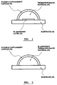
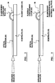
- a quantity of thermopneumatic material 32 Within the capsule 30 is a quantity of thermopneumatic material 32.
- an infrared radiation absorbing layer 16 is disposed within the capsule 30.
- infrared radiation is applied to the capsule 30 at or close to the location of the infrared radiation absorbing layer 16, thereby causing the thermopneumatic material 32 within the capsule 30 to be heated.
- the thermopneumatic material 32 As the thermopneumatic material 32 is heated, it expands in volume and causes movement of the flexible material forming the capsule 30, i.e. it causes mechanical movement thereof.
- the thermopneumatic material 32 cools, it returns to its original volume and the flexible material of the capsule returns to its original position accordingly.
- thermopneumatic material 32 within the capsule 30 may itself be infrared radiation absorbing by nature, thereby eliminating the need for an infrared radiation absorbing layer within the capsule 30.
- the thermopneumatic material 32 may, for example, be treated by (say) adding a dye thereto so as to make it absorbant of the incident radiation (in this case, IR).
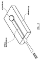
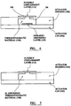
- the actuator illustrated in Figures 4 and 5 of the drawings is similar in many respects to that shown in (and described with reference to) Figures 5 to 7, except in this case, the actuator comprises a chamber 80 formed by a flexible containment layer 82, and an infrared absorbing thermopneumatic material 84 (e.g. wax) is provided within the chamber 80.
- a beam 58 of infrared radiation is applied to the optical waveguide 56, which carries the radiation to the flexible containment layer 82 through which it travels and causes the thermopneumatic material 84 within the chamber 80 to be heated.
- the material 84 expands in volume and causes mechanical movement of the flexible containment layer 82.
- the thermopneumatic material 84 cools, it returns to its original volume and the flexible containment layer 82 returns to its original position.
- an actuator according to another exemplary embodiment of the present invention, comprises a housing 100 mounted on a cap 102.
- the housing 100 defines a chamber 104 with a gap 106 at the top.
- a quantity of thermopneumatic material 108 and an infrared radiation absorbing layer 110 Within the chamber 104 there is a quantity of thermopneumatic material 108 and an infrared radiation absorbing layer 110.
- a flexible containment layer 112 is provided over the gap 106 in the chamber 104.
- infrared radiation is applied to the infrared radiation absorbing layer 110 causing the thermopneumatic 108 material to be heated and to expand in volume accordingly.
- Such expansion in volume of the thermopneumatic material 108 causes movement of the flexible containment layer 112.
- the resultant phase change causes it to return to its original volume such that the flexible containment layer 112 returns to its original position.
- thermopneumatic material 108 is itself infrared radiation absorbing in nature (or treated to make it so), thereby eliminating the necessity for a separate infrared radiation absorbing layer within the chamber 104.
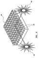
- a system 120 comprises a three-dimensional array of components 122 according to the invention.
- Two infrared radiation sources 124, 126 are provided to supply all of the components within the system 120.
- the radiation sources 124, 126 are at an angle, say, perpendicular to each other, as shown, and their beams are arranged to intersect at a location in or on at least one component required to be heated.
- the energy at the intersection of the beams is sufficient to heat.
- the energy at any other point is generally not.
- a control system (not shown) is provided to enable the component(s) to be heated to be selected and to control the application of infrared radiation from the sources 124, 126 accordingly.
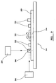
- a plurality of micro-valves 222 are mounted on the surface of a disc-like substrate 223.
- the substrate 223 is provided with central aperture 230 for mounting the substrate 223 on a spindle 232 of a compact disc player 233 or the like.
- One or more laser sources 234, 236 are provided (as in a standard compact disc reader, for playing music or running software, for example), laser radiation from which impinges on the upper surface of the substrate 223.
- the micro-valves 222 are arranged concentrically around the substrate 223. In the illustrated example, two laser sources 234, 236 are provided, the radiation beams from which intersect at point zero.
- each of the components 222 passes through point 240 and is actuated, as required.
- yet another specific exemplary embodiment of the present invention comprises one or more valves provided in or on a fluidic platform 300, which is configured to be received in a recess of 302 of a base unit 304.
- the fluidic platform 300 of this exemplary embodiment of the present invention created in two halves 300a, 300b which, when placed together, define a hollow recess 301 between them.
- the upper half 300a of the platform has a fluid inlet 306 leading to the upper half of the recess 301, and the lower half 300b of the platform has a fluid outlet 308 leading out from the lower half of the recess 301.
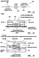
- the valve 310 comprises two flexible membranes 312, 314 which are brought together around a quantity of thermopneumatic material 316 and sealed at the edges to define a flexible chamber filled with thermopneumatic material 316, such as wax.
- Figures 12 and 13 of the drawings illustrate the completed fluidic platform 300.
- the outer (sealed) edges 313 of the actuator structure and valve membrane 312, 314 is provided with one or more through holes 322.
- a valve seat 320 is defined generally centrally, and a waveguide 324 may be provided to transmit electromagnetic radiation to the valve 310, although the EM radiation may, of course, be provided directly thereto.
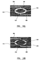
- thermopneumatic material 316 expands, causing the valve chamber to expand within the recess 301 and block the path between the inlet 306 and the outlet 308, thereby preventing fluid flow ( Figure 14B).
- thermopneumatic material 316 contracts back to its original volume, thereby reducing the size of the valve chamber and unblocking the flow path between the inlet 306 and the outlet 308, so that fluid flow there between can resume (see Figure 14A).
- Figure 15 of the drawings is a schematic illustration of an IR-actuated component or system according to an exemplary embodiment of the present invention, comprising a fluidic layer 401 containing the valve structures, micro-pumps, etc., an actuator "layer” 402 which effectively just represents the actuator function, an optics layer 403, and a cooling layer 404, which could alternatively be positioned on the other side of the fluidic layer 401.
- a fluidic component such as a micro-valve 500 or pump chamber, according to an exemplary embodiment of the present invention comprises an actuator layer 501 and a fluidic layer 502 with a flexible valve membrane 503 sandwiched between them.
- the actuator layer 501 comprises an actuator block 504 defining a chamber 505 which contains a thermopneumatic material such as wax, fluoro-inert gas, etc.
- the valve membrane 503 is bonded directly to the actuator block 504, sealing the chamber 505, without the need for adhesive.
- the fluidic layer which may be directly bonded to the actuator block 502 defines an inlet channel 506, an outlet channel 507, and valve seat 508 with which the valve membrane 503 co-operates to selectively open or close the fluid flow path between the inlet and outlet channels 506, 507.
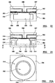
- a micro-valve 500 is similar in many respects to that described with reference to Figure 18, in that it comprises an actuator layer 501 and a fluidic layer 502 with a valve membrane 503 sandwiched between them.
- the actuator 502 again comprises an actuating block 504 defining a chamber 505 containing a thermopneumatic material.
- the fluidic layer 502 defines an inlet channel 506, an outlet channel 507 and a valve seat 508 with which the valve membrane 503 co-operates to selectively open and close the fluid flow path between the inlet and outlet channels 506, 507.
- the fluidic layer 502 and valve membrane may be fabricated as an integrated unit using direct bonding, such that there is no adhesive between these parts.
- the actuator block 504 may be fabricated separately, with an actuator diaphragm 509 sealing the chamber 505, and adhesive bonded onto the fluidic layer 502 by, for example, one or more adhesive pads 510 which may be screen printed or otherwise provided on the actuator block 504.
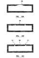
- Figures 18A, B and C illustrate possible designs for the actuator diaphragm 509 by way of examples only.
- the actuator diaphragm 509 of Figure 18A is designed to achieve maximum deflection of the centre of the diaphragm
- the actuator diaphragm 509 of Figure 18B is designed to maintain the deflecting part of the membrane relatively flat
- Figure 18C illustrates another flat actuating design with concertina structures 511 at the edges of the flat deflection part to allow greater travel of the membrane 509.
- FIG 19 there is illustrated a modified version of the valve of Figure 17, in which the actuator membrane 509 is eliminated, and in which sealing structures 512 are provided around the opening of the chamber or reservoir 505 containing the thermopneumatic material (e.g. wax).
- the sealing structures 512 are raised areas that, when in contact with the valve membrane 503 and when under compressive pressure, seal the contents of the reservoir 505.
- the main advantage of this construction is that there is no direct contact between the contents of the actuator reservoir 505 and the adhesive used to construct the device.
- the fluidic layer 502 and valve membrane 503 may be held in contact with the actuator layer 501 by adhesive pads 510 between the two layers.
- the adhesive might be, for example, a). polymeric, two-part or single component, heat, UV or light cured, hot melt, etc; b). metallic interlayers eutectic bonding, e.g. solder type; c) etc.
- the adhesive may be introduced as an underfill, but other methods include painting, screen printing, drop dispensing, spraying, spincoting, dipping, etc., to provide an actuated valve of relatively simple construction.
- Figure 20 of the drawings illustrates a valve similar to that of Figure 19, in which the valve membrane 503 is trapped between opposing sealing structures 512a, 513b provided on both the fluidic and actuator layers 502, 501 respectively. It can, for example, be introduced as a separate layer that is sandwiched between the fluidic and actuator layers 502, 501. It will be appreciated that this design requires adhesion of the fluidic and actuator layers 502, 501 directly to the membrane 503, which may not be possible in the case where the membrane 503 is formed of, or coated with, a non-stick material such PTFE or the like.
- valve 500 according to another exemplary embodiment of the present invention, in which this problem is overcome by providing through-holes 513 in the valve membrane 503 through which the adhesive 510 can flow such that it can adhere to the surface of the fluidic layer 502 and actuator block 504.
- valve 500 according to yet another exemplary embodiment of the present invention is similar in many respects to that of Figure 23, except for the design of the valve seat 508, the construction of which is such that the valve membrane 503 selectively opens and closes both the inlet and outlet channels 506, 507, in operation (i.e. there is no step provided between the inlet and outlet channels 506, 507).
- valve seat 508 Many different designs of valve seat 508 can be envisaged, and the present invention is not intended to be limited in this regard.
- Figures 23 and 23A of the drawings illustrate a valve similar in many respects to that of Figure 22, except that, in this case, a coding channel 514 is provided in the actuator block 504 around the reservoir 505. Gaseous and/or liquid codants can be caused to flow through the coding channels 514 (via inlet coding channel 515 and outlet channel 516) to provide cooling of the device. It will be appreciated that the illustrated design is schematic and would be optimised for specific embodiment.
- thermo-electric elements 517 can be attached to strategic points on the device 500 to provide localised cooling. This cooling can be defused across the device by providing a thermally conductive layer that conducts the heat from the device to the thermo-electric elements.
- the actuator body 504 could be fabricated from silicon or metal and the thermo-electric elements 517 could be attached directly to the actuator block 504. At least in the case where the actuator body is fabricated of metal, a waveguide or optical fibre is provided in direct contact with the thermopneumatic material within the reservoir 505 to supply electromagnetic radiation thereto.
- cooling can also be provided by:
- the internal structure of the wax actuator can be designed to accommodate features that improve the thermal conduction between the wax and the actuator body. This would only work if the material used to fabricate the actuator body is IR transparent. This would avoid complicated schemes for structuring the IR radiation to match the design features built into the actuator body.
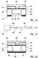
- the actuator body may be formed an IR transparent material, in which one or more pits are formed by means of direct etching.
- the material chosen for the actuator body is bonded to an IR transparent material 520 (actuator body capping layer) and the actuator reservoir 505 is etched to expose the IR transparent material. This creates an IR transparent window into the reservoir. This can also be accomplished by forming the reservoir 505 in the actuator body 504 and then bonding the IR transparent window material 520. This is illustrated in Figure 26 of the drawings.
- thermopneumatic material such as wax
- an inlet 521 and outlet 522 is used to introduce wax in its molten state into the reservoir 505, following which the inlet and outlet 521, 522 would be blocked. It will be appreciated by a person skilled in the art that there are several methods available for doing this. The wax then cools and hardens.
- FIG. 29 there is illustrated an array of wax reservoirs 505 constructed so as to allow the entire collection of actuators to be filled simultaneously.
- Figure 30 illustrates a similar arrangement, in which reservoir isolator structures or check valves 524 are provided between the reservoirs 505 and each other, the associated inlet 521 and outlet 522.
- the concept of the check valve 524 is to prevent back-flow of wax from one actuator 505 to another.
- the check valve 524 may comprise a volume of wax that is structured to provide a significant sealing structure, particularly when adjacent actuators 505 have been activated and are in the liquid state.
- the check valves 524 should not only act as seals, but are beneficially constructed to fill uniformly across the entire collection of actuators 505. Examples are illustrated in Figures 30A and 30B of the drawings.
- an open reservoir 525 for the wax material is provided, in which the actuators 505 are defined by the position of an IR beam 526 and the location of the thinned areas on the actuator body 504.
- the IR energy can be delivered directly to the sites of the actuators through IR transparent sections of the device, as illustrated in Figure 32 of the drawings.
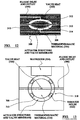
- electromagnetic energy may be delivered to the actuators by means of optical waveguides 550 fabricated using a variety of approaches including:
- FIG. 33 of the drawings represents a waveguide edge connected to each actuator. These link the optical interface present at a convenient location on the outside of the device to the actuators located inside the device. Each waveguide is linked to a separate actuator.
- Electromagnetic energy for example, infrared radiation
- the waveguide then ports the radiation to the actuator. It will be appreciated that the plainer layout of these waveguides can vary according to design requirements.
- each actuator is placed on a waveguide.
- the waveguides perform the same function as outlined in respect of the embodiment shown in Figure 33 of the drawings.
- optical structures for example, gratings that re-orientate the light from the longitudinal access of the waveguide into the actuator.
- each waveguide is linked to a separate actuator, infrared radiation is focussed onto the optical facet of the respective waveguide and the waveguide then ports the radiation to the actuator.
- the plainer layout of these waveguides can vary according to design requirements.
- the interface between the optical waveguide and the actuator may be modified to control the quantity of light available to the actuator. Although this may not be as important in a single actuator system, it may become a significant issue in respect of multi-actuator systems.
- These interfaces can be optical gratings that deflect a proportion of light at right angles to the longitudinal access of the waveguide, optical apertures (irises), optical part reflective coatings, etc.
- Delivery of the infrared beam can be by a single beam arrangement using conventional methods of beam delivery. These may be lenses, fibre, mirrors, etc. Delivery of the beam onto positions on a two-dimensional plain could be performed using the XY scanning mirror approach illustrated in Figure 35 of the drawings.
- the optical interface would either be a direct link to the wax actuator or an interface to the optical conduit linking the outside of the system with actuators located within the three dimensional structure of the system.
- delivery of infrared radiation may be achieved by high power LED devices. These can either by used singly (one per actuator) or in arrays that register with arrays of optical input on the actuator layer.
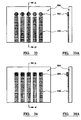
- Figure 36 of the drawings illustrates an LED matrix, the LED's of which are individually addressable, and aligns with actuator sights or optical interfaces servicing these actuators.
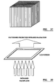
- FIG. 37 of the drawings illustrates an optical fibre bundle in which the optical facets line up with the respective actuator sights or respective optical interfaces servicing these sights.
- Each fibre can be located accurately in two dimensions and each position registers with the position of an actuator.
- an iris is provided which allows the beam to be switched on and off.
- the same control can be afforded by switching the laser on and off.
- This is particularly but not exclusively, suited to laser diodes.
- the XY scanning mirrors 600 and the iris or laser diodes switching can be controlled via a computer program.
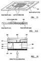
- the control data is formulated as a series of images (ie like frames in a movie sequence). Each frame draws in a checkered bitmap representing the on/off state of each actuator.
- the computer scrolls through these frames converting them to images on the optical interface of the systems using the XY mirrors 600 and the laser on/off control, similar to the control of the E-beam on a television (see Figure 38 of the drawings).
- Figure 39 illustrates an LED screen which can be used to create or define a region of opacity through which the EM radiation cannot pass.
- Figure 40 of the drawings illustrates a system comprising a plurality of actuators 505 directly accessible through one or more IR transparent windows, and a plurality of optical interfaces 700 servicing actuation via waveguides, for example, optical fibres.
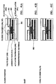
- Figures 41 A, B and C illustrate a valve according to yet another exemplary embodiment of the present invention, wherein the actuator layer 501 defines two chambers 801, 802 linked by a relatively narrow fluidic junction 803.
- a thermopneumatic material such as wax fills the upper chamber 801 and maintains the actuator diaphragm 509 in the level position, thereby maintaining the fluid flow path between the inlet and outlet channels 506,507 of the fluidic layer 502 closed.
- the wax When the wax is heated, it expands and fills the second chamber 802, and because the fluidic junction 803 is relatively narrow, it cools first, to block the flow of wax back in to the first valve chamber 801. The wax is then cooled, so that the volume in the chamber 801, is reduced and the actuator diaphragm 509 contracts to open the fluid flow path between the inlet and outlet channels 506, 507.
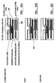
- FIG. 42A, B and C Yet another exemplary embodiment of the valve according to the present invention is illustrated in Figures 42A, B and C in which the second wax reservoir (802) of Figure 41 is replaced by a capillary channel 804.
- the solid wax substantially fills the first chamber 801 and maintains the actuator diaphragm 509 in its level position, thereby maintaining the fluid flow path between the inlet and the outlet channels 506, 507 closed.
- the wax expands and fills the capillary channel 804.
- the wax cools in the capillary channel 804 it accommodates an additional proportion of the wax volume, which reduces the volume in the upper valve chamber 801, and causes the actuator diaphragm 509 to contract and open the valve.
- FIG. 43 of the drawings there is shown a schematic illustration of the principle components of an insulin pump 900, comprising a pump 902 having check valves 904,906 on each side of it.
- the pump 902 may comprise defining a chamber 909 having an inlet 908 and an outlet 910 with a flow path therebetween.
- a flexible membrane 912 is provided within the chamber 909 which confines a body of thermopneumatic material, such as wax 914.
- An electromagnetic source 916 such as an LED or laser diode, is provided within the body of thermopneumatic material 914, and electrical contacts 918 are provided to supply energy thereto.
- thermopneumatic material 914 In use, electromagnetic energy (from the source 916 and/or an external source) is provided to the thermopneumatic material 914 to heat it and cause a phase change, which causes the material 914 to expand. As a result the membrane 912 moves upwards to block the flow path between the inlet 908 and the outlet 910. When the wax 914 is allowed to cool, it hardens and contracts, such that the flow path is re-opened.
- the check valve (904 or 906) may comprise a housing defining a chamber 920 having an inlet 922 and an outlet 924.
- the inlet 922 is separated from the chamber 920 by a first flexible flap or membrane 926 and the outlet 924 is separated from the chamber 920 by a second flexible flap or membrane 928.
- Each of the flaps 926,928 has a respective chamber 930,932 filled with wax attached thereto, and an electromagnetic radiation source 934, such as an LED, is provide within the chamber 920.
- a hydraulic chamber 936 or the like may be provided between the membrane 912 and the flow path, as shown in Figure 46 for example, to counteract the effects of uneven movement of the membrane 912 (caused by the expansion and contraction of the thermopneumatic material 914) and improve control.
- electromagnetic radiation to heat the components of the present invention substantially simplifies the process of transferring actuation energy to site specific points within a system. It provides high intensity energy which can, of course, be of a specific wavelength for operation of the components.
Landscapes
- Engineering & Computer Science (AREA)
- General Engineering & Computer Science (AREA)
- Mechanical Engineering (AREA)
- Chemical & Material Sciences (AREA)
- Dispersion Chemistry (AREA)
- Microelectronics & Electronic Packaging (AREA)
- Toxicology (AREA)
- Computer Hardware Design (AREA)
- Health & Medical Sciences (AREA)
- Theoretical Computer Science (AREA)
- Physics & Mathematics (AREA)
- Fluid Mechanics (AREA)
- Micromachines (AREA)
- Fluid-Pressure Circuits (AREA)
- Steroid Compounds (AREA)
- Addition Polymer Or Copolymer, Post-Treatments, Or Chemical Modifications (AREA)
Claims (15)
- Ein System enthaltend mindestens eine Komponente (222, 300, 509, 902, 904, 906), von der mindestens ein Teil erhitzt werden muss, damit deren Funktion bewirkt wird, und eine elektromagnetische Strahlungsquelle (124, 126, 916, 934) zum Erhitzen dieser Komponente, wobei die Komponente eine Kammer (30, 80, 104, 505, 801, 909, 920) beinhaltet, die zumindest teilweise aus einem flexiblen Material (82, 312, 314, 912) gebildet ist, wobei die Kammer ein thermopneumatisches Material (32, 84, 108, 316, 509, 914) aufnimmt, und wobei das System so angeordnet ist, dass, wenn das thermopneumatische Material durch die elektromagnetische Strahlungsquelle erhitzt wird, das thermopneumatische Material innerhalb der Kammer expandiert und so eine Bewegung des flexiblen Materials bewirkt,
dadurch gekennzeichnet, dass
das thermopneumatische Material ein Wachs (914) ist, welches aufgrund einer Phasenumwandlung durch Erhitzen einer Volumenexpansion unterliegt, und
das ein elektromagnetische Strahlung absorbierendes Material in Form eines Additivs in das Wachs eingebracht worden ist, wobei das elektromagnetische Strahlung absorbierende Material bei seinem Einsatz Infratrot-Strahlung einer gegebenen Wellenlänge von der elektromagnetischen Strahlungsquelle absorbiert, um so eine Temperaturerhöhung im Wachs zu bewirken. - Ein System nach Anspruch 1, wobei das Wachs im Wesentlichen durchlässig ist für die elektromagnetische Strahlung der gegebenen Wellenlänge.
- Ein System nach Anspruch 1 oder 2, wobei das Additiv ein Farbstoff ist.
- Ein System nach irgendeinem der vorhergehenden Ansprüche, wobei die Komponente ein Ventil (222, 500), eine Pumpenkammer, eine Pumpe, ein beweglicher Spiegel, eine bewegliche Linse, ein Reaktor, ein Aktor (300), ein Sensor, eine Reaktionskammer oder Miniatur- oder Mikroausführungen davon ist.
- Ein System nach irgendeinem der vorhergehenden Ansprüche, wobei die elektromagnetische Strahlungsquelle als Teil von oder innerhalb einer jeden Komponente bereitgestellt wird.
- Ein System nach irgendeinem der vorhergehenden Ansprüche, beinhaltend mindestens zwei elektromagnetische Strahlungsquellen (124, 126, 234, 236), wobei deren Strahlung so angeordnet sind, dass sie sich an einem Ort in oder auf der mindestens einen Komponente, die zu erhitzen ist, kreuzen.
- Ein System nach Anspruch 6, wobei eine oder mehrere der elektromagnetischen Strahlungsquellen beweglich sind, um so den Ort zu ändern, an dem sich die Strahlen kreuzen.
- Ein System nach einem der vorhergehenden Ansprüche, umfassend eine Vielzahl dieser Komponenten.
- Ein System nach Anspruch 8, wobei mindestens einige dieser Komponenten so angeordnet sind, dass sie selektiv durch eine gleiche Strahlungsquelle oder durch mehrere Strahlungsquellen erhitzt werden.
- Ein System nach einem der vorhergehenden Ansprüche, enthaltend einen oder mehrere optische Wellenleiter (56, 550) oder optische Fasern, um elektromagnetische Strahlung an der einen Komponente oder den mehreren Komponenten bereitzustellen.
- Ein System nach Anspruch 10, wobei die elektromagnetische Strahlungsquelle relativ zur dem einen Wellenleiter oder den mehreren Wellenleitern oder optischen Fasern beweglich ist.
- Ein System nach irgendeinem der Ansprüche 1 bis 9, wobei die elektromagnetische Strahlungsquelle ein fokussierter Strahl oder ein Laserstrahl ist, der so gerichtet ist, dass er elektromagnetische Strahlung an der einen Komponente oder den mehreren Komponenten direkt bereitstellt.
- Ein System nach irgendeinem der vorhergehenden Ansprüche, wobei die elektromagnetische Strahlungsquelle (234, 236) relativ zu der mindestens einen Komponente (222) beweglich ist.
- Ein System nach irgendeinem der vorhergehenden Ansprüche, wobei die elektromagnetische Strahlungsquelle einen Laser (234, 236), eine Laserdiode, eine Licht emittierende Diode oder eine Glüh-Lichtquelle umfasst.
- Eine Komponente (222, 300, 509, 902, 904, 906), von der mindestens ein Teil erhitzt werden muss, damit deren Funktion bewirkt wird, wobei die Komponente eine Kammer (30, 80, 104, 505, 801, 909, 920) beinhaltet, die zumindest teilweise aus einem flexiblen Material (82, 312, 314, 912) gebildet ist, wobei die Kammer ein thermopneumatisches Material (32, 84, 108, 316, 509, 914) aufnimmt wobei die Komponente so angeordnet ist, dass, wenn das thermopneumatische Material durch eine elektromagnetische Strahlungsquelle erhitzt wird, das thermopneumatische Material innerhalb der Kammer expandiert und so eine Bewegung des flexiblen Materials bewirkt,
dadurch gekennzeichnet, dass
das thermopneumatiscbe Material ein Wachs (914) ist, welches aufgrund einer Phasenumwandlung durch Erhitzen einer Volumenexpansion unterliegt, und
das ein elektromagnetische Strahlung absorbierendes Material in Form eines Additivs in das Wachs eingebracht worden ist, wobei das elektromagnetische Strahlung absorbierende Material bei seinem Einsatz Infratrot-Strahlung einer gegebenen Wellenlänge von der elektromagnetischen Strahlungsquelle absorbiert, um so eine Temperaturerhöhung im Wachs zu bewirken.
Applications Claiming Priority (5)
| Application Number | Priority Date | Filing Date | Title |
|---|---|---|---|
| GB0206912A GB0206912D0 (en) | 2002-03-23 | 2002-03-23 | Components |
| GB0206912 | 2002-03-23 | ||
| GB0219092A GB0219092D0 (en) | 2002-08-16 | 2002-08-16 | Components |
| GB0219092 | 2002-08-16 | ||
| PCT/GB2003/001218 WO2003081052A1 (en) | 2002-03-23 | 2003-03-21 | Macromechanical components |
Publications (2)
| Publication Number | Publication Date |
|---|---|
| EP1490601A1 EP1490601A1 (de) | 2004-12-29 |
| EP1490601B1 true EP1490601B1 (de) | 2007-08-15 |
Family
ID=28456029
Family Applications (1)
| Application Number | Title | Priority Date | Filing Date |
|---|---|---|---|
| EP03710004A Expired - Lifetime EP1490601B1 (de) | 2002-03-23 | 2003-03-21 | Mikromechanische bauelemente |
Country Status (7)
| Country | Link |
|---|---|
| US (1) | US20060044084A1 (de) |
| EP (1) | EP1490601B1 (de) |
| CN (1) | CN1653274A (de) |
| AT (1) | ATE370338T1 (de) |
| AU (1) | AU2003214432A1 (de) |
| DE (1) | DE60315616D1 (de) |
| WO (1) | WO2003081052A1 (de) |
Cited By (1)
| Publication number | Priority date | Publication date | Assignee | Title |
|---|---|---|---|---|
| US11852423B2 (en) | 2021-02-03 | 2023-12-26 | Toyota Motor Engineering & Manufacturing North America, Inc. | Systems and methods for tunable radiative cooling |
Families Citing this family (19)
| Publication number | Priority date | Publication date | Assignee | Title |
|---|---|---|---|---|
| US20080172026A1 (en) | 2006-10-17 | 2008-07-17 | Blomquist Michael L | Insulin pump having a suspension bolus |
| GB2400158B (en) * | 2003-04-02 | 2006-03-22 | Starbridge Systems Ltd | Fluidic devices |
| EP1790861A1 (de) | 2005-11-25 | 2007-05-30 | Bonsens AB | Mikrofluidisches System |
| TWI404929B (zh) * | 2006-07-17 | 2013-08-11 | Ind Tech Res Inst | 流體裝置及其控制方法 |
| EP1884284A1 (de) | 2006-08-04 | 2008-02-06 | Samsung Electronics Co., Ltd. | Absperrventileinheit und Reaktionsvorrichtung mit Absperrventil |
| DE102008013098B4 (de) * | 2007-04-02 | 2012-02-09 | Fraunhofer-Gesellschaft zur Förderung der angewandten Forschung e.V. | Mikromechanisches System mit Temperaturstabilisierung |
| US8986253B2 (en) | 2008-01-25 | 2015-03-24 | Tandem Diabetes Care, Inc. | Two chamber pumps and related methods |
| US8926561B2 (en) | 2009-07-30 | 2015-01-06 | Tandem Diabetes Care, Inc. | Infusion pump system with disposable cartridge having pressure venting and pressure feedback |
| US9180242B2 (en) | 2012-05-17 | 2015-11-10 | Tandem Diabetes Care, Inc. | Methods and devices for multiple fluid transfer |
| US9173998B2 (en) | 2013-03-14 | 2015-11-03 | Tandem Diabetes Care, Inc. | System and method for detecting occlusions in an infusion pump |
| FR3015310B1 (fr) * | 2013-12-24 | 2020-09-11 | Espci Innov | Dispositif de manipulation, de tri, de generation et de stockage d'un element d'un fluide non miscible et dispositif de fusion de deux tels elements |
| CN105465480B (zh) * | 2015-11-16 | 2018-11-30 | 中国科学院理化技术研究所 | 一种相变阀装置及其制备方法 |
| CN105805400A (zh) * | 2016-05-16 | 2016-07-27 | 江苏微全芯生物科技有限公司 | 温控阀芯组件、温控阀、微流道控制芯片及控制系统 |
| CN108217576B (zh) * | 2016-12-21 | 2020-05-22 | 上海傲睿科技有限公司 | 膜片截止阀及其制造方法 |
| EP3348886B1 (de) * | 2017-01-13 | 2019-11-27 | Consejo Superior De Investigaciones Cientificas | Mikrofluidisches ventil |
| JP7317836B2 (ja) * | 2017-12-28 | 2023-07-31 | フィリップ・モーリス・プロダクツ・ソシエテ・アノニム | 表面が変化するエアロゾル発生システム |
| GB202006168D0 (en) * | 2020-04-27 | 2020-06-10 | Exergyn Ltd | Shape memory alloy heat pump |
| EP4068249B1 (de) | 2021-03-31 | 2024-10-09 | Glassomer GmbH | Vorrichtung und verfahren zum verschieben eines fluids in einem fluidkanal, verwendung der vorrichtung und taktile anzeige |
| WO2025213039A1 (en) * | 2024-04-05 | 2025-10-09 | The Regents Of The University Of California | Actuators |
Family Cites Families (15)
| Publication number | Priority date | Publication date | Assignee | Title |
|---|---|---|---|---|
| US3782121A (en) * | 1972-05-01 | 1974-01-01 | Texas Instruments Inc | Actuator apparatus |
| DE3109133C2 (de) * | 1981-03-11 | 1991-03-28 | Behr-Thomson Dehnstoffregler Gmbh, 7014 Kornwestheim | Elektrisches Schaltgerät mit einem thermostatischen Arbeitselement als Betätigungselement und mit einem als Mikroschalter ausgebildeten Schaltelement |
| GB2150780B (en) * | 1983-11-30 | 1986-10-08 | Standard Telephones Cables Ltd | Optical actuator |
| US4749856A (en) * | 1983-12-07 | 1988-06-07 | Monsanto Company | Wavelength-independent polymer/optical sensing apparatus and method |
| US4824073A (en) * | 1986-09-24 | 1989-04-25 | Stanford University | Integrated, microminiature electric to fluidic valve |
| US5222362A (en) * | 1989-01-10 | 1993-06-29 | Maus Daryl D | Heat-activated drug delivery system and thermal actuators therefor |
| US5238223A (en) * | 1989-08-11 | 1993-08-24 | Robert Bosch Gmbh | Method of making a microvalve |
| JP3328300B2 (ja) * | 1991-07-18 | 2002-09-24 | アイシン精機株式会社 | 流体制御装置 |
| US5367878A (en) * | 1991-11-08 | 1994-11-29 | University Of Southern California | Transient energy release microdevices and methods |
| US5253198A (en) * | 1991-12-20 | 1993-10-12 | Syracuse University | Three-dimensional optical memory |
| US6166361A (en) * | 1998-02-02 | 2000-12-26 | Bettinger; David S. | Actuators released by remote microwave radiation |
| FI981432A7 (fi) * | 1998-06-22 | 2000-01-14 | Niilo Kaartinen | Jäähana |
| US6160243A (en) * | 1998-09-25 | 2000-12-12 | Redwood Microsystems, Inc. | Apparatus and method for controlling fluid in a micromachined boiler |
| US6952962B2 (en) * | 2000-10-24 | 2005-10-11 | Sandia National Laboratories | Mobile monolithic polymer elements for flow control in microfluidic devices |
| WO2005036182A1 (ja) * | 2003-10-15 | 2005-04-21 | Matsushita Electric Industrial Co., Ltd. | キャピラリチップにおける流体の流通方法 |
-
2003
- 2003-03-21 EP EP03710004A patent/EP1490601B1/de not_active Expired - Lifetime
- 2003-03-21 AU AU2003214432A patent/AU2003214432A1/en not_active Abandoned
- 2003-03-21 US US10/508,609 patent/US20060044084A1/en not_active Abandoned
- 2003-03-21 CN CNA038102277A patent/CN1653274A/zh active Pending
- 2003-03-21 WO PCT/GB2003/001218 patent/WO2003081052A1/en not_active Ceased
- 2003-03-21 AT AT03710004T patent/ATE370338T1/de not_active IP Right Cessation
- 2003-03-21 DE DE60315616T patent/DE60315616D1/de not_active Expired - Lifetime
Cited By (1)
| Publication number | Priority date | Publication date | Assignee | Title |
|---|---|---|---|---|
| US11852423B2 (en) | 2021-02-03 | 2023-12-26 | Toyota Motor Engineering & Manufacturing North America, Inc. | Systems and methods for tunable radiative cooling |
Also Published As
| Publication number | Publication date |
|---|---|
| DE60315616D1 (de) | 2007-09-27 |
| AU2003214432A1 (en) | 2003-10-08 |
| EP1490601A1 (de) | 2004-12-29 |
| US20060044084A1 (en) | 2006-03-02 |
| CN1653274A (zh) | 2005-08-10 |
| WO2003081052A1 (en) | 2003-10-02 |
| ATE370338T1 (de) | 2007-09-15 |
Similar Documents
| Publication | Publication Date | Title |
|---|---|---|
| EP1490601B1 (de) | Mikromechanische bauelemente | |
| AU625229B2 (en) | Integrated, microminiature electric-to-fluidic valve and pressure/flow regulator | |
| US4943032A (en) | Integrated, microminiature electric to fluidic valve and pressure/flow regulator | |
| US8066031B2 (en) | Electro-hydraulic devices | |
| US4821997A (en) | Integrated, microminiature electric-to-fluidic valve and pressure/flow regulator | |
| US8221704B2 (en) | Microfluidic device and microfluidic system with the same | |
| US7595925B2 (en) | Actuating device having a flexible diaphragm controlled by electrowetting | |
| US7650910B2 (en) | Electro-hydraulic valve apparatuses | |
| US6283440B1 (en) | Apparatus and method for regulating fluid flow with a micro-electro mechanical block | |
| US12360361B2 (en) | Advanced packaging for compact object-scanning modules | |
| Paik et al. | A digital-microfluidic approach to chip cooling | |
| CN108679301A (zh) | 一种微阀与液体之间的隔离系统、控制方法及生物芯片 | |
| US9157551B2 (en) | Reconfigurable microactuator and method of configuring same | |
| US9151483B2 (en) | Heat pipe for cooling optical sources | |
| EP3348886B1 (de) | Mikrofluidisches ventil | |
| JP5015783B2 (ja) | 流体検査システム | |
| US20040011977A1 (en) | Micro-fluidic valves | |
| Hua et al. | A light writable microfluidic “flash memory”: Optically addressed actuator array with latched operation for microfluidic applications | |
| CN108591610B (zh) | 一种微流控系统及微阀、控制方法 | |
| US20070018008A1 (en) | Variable orifice valve | |
| Rahman et al. | Parallel actuation of multiple bubble microrobots in saline solution in an open reservoir | |
| WO2002018827A1 (en) | Micro-fluidic valves | |
| CN108843855A (zh) | 一种微流控系统及常闭微阀、控制方法 | |
| JPS6110972A (ja) | アクチユエ−タエレメント | |
| JPH04265477A (ja) | 熱操作アクチュエータ |
Legal Events
| Date | Code | Title | Description |
|---|---|---|---|
| PUAI | Public reference made under article 153(3) epc to a published international application that has entered the european phase |
Free format text: ORIGINAL CODE: 0009012 |
|
| 17P | Request for examination filed |
Effective date: 20041022 |
|
| AK | Designated contracting states |
Kind code of ref document: A1 Designated state(s): AT BE BG CH CY CZ DE DK EE ES FI FR GB GR HU IE IT LI LU MC NL PT RO SE SI SK TR |
|
| AX | Request for extension of the european patent |
Extension state: AL LT LV MK |
|
| 17Q | First examination report despatched |
Effective date: 20050627 |
|
| GRAP | Despatch of communication of intention to grant a patent |
Free format text: ORIGINAL CODE: EPIDOSNIGR1 |
|
| GRAS | Grant fee paid |
Free format text: ORIGINAL CODE: EPIDOSNIGR3 |
|
| RIN1 | Information on inventor provided before grant (corrected) |
Inventor name: SHAPLEY, JULIAN Inventor name: MARTINEAU, PETER Inventor name: SMITH, KEVIN Inventor name: CEFAI, JOSEPH |
|
| GRAA | (expected) grant |
Free format text: ORIGINAL CODE: 0009210 |
|
| AK | Designated contracting states |
Kind code of ref document: B1 Designated state(s): AT BE BG CH CY CZ DE DK EE ES FI FR GB GR HU IE IT LI LU MC NL PT RO SE SI SK TR |
|
| REG | Reference to a national code |
Ref country code: GB Ref legal event code: FG4D |
|
| REG | Reference to a national code |
Ref country code: CH Ref legal event code: EP |
|
| REG | Reference to a national code |
Ref country code: IE Ref legal event code: FG4D |
|
| REF | Corresponds to: |
Ref document number: 60315616 Country of ref document: DE Date of ref document: 20070927 Kind code of ref document: P |
|
| PG25 | Lapsed in a contracting state [announced via postgrant information from national office to epo] |
Ref country code: ES Free format text: LAPSE BECAUSE OF FAILURE TO SUBMIT A TRANSLATION OF THE DESCRIPTION OR TO PAY THE FEE WITHIN THE PRESCRIBED TIME-LIMIT Effective date: 20071126 Ref country code: BG Free format text: LAPSE BECAUSE OF FAILURE TO SUBMIT A TRANSLATION OF THE DESCRIPTION OR TO PAY THE FEE WITHIN THE PRESCRIBED TIME-LIMIT Effective date: 20071115 Ref country code: FI Free format text: LAPSE BECAUSE OF FAILURE TO SUBMIT A TRANSLATION OF THE DESCRIPTION OR TO PAY THE FEE WITHIN THE PRESCRIBED TIME-LIMIT Effective date: 20070815 Ref country code: NL Free format text: LAPSE BECAUSE OF FAILURE TO SUBMIT A TRANSLATION OF THE DESCRIPTION OR TO PAY THE FEE WITHIN THE PRESCRIBED TIME-LIMIT Effective date: 20070815 |
|
| NLV1 | Nl: lapsed or annulled due to failure to fulfill the requirements of art. 29p and 29m of the patents act | ||
| PG25 | Lapsed in a contracting state [announced via postgrant information from national office to epo] |
Ref country code: CH Free format text: LAPSE BECAUSE OF FAILURE TO SUBMIT A TRANSLATION OF THE DESCRIPTION OR TO PAY THE FEE WITHIN THE PRESCRIBED TIME-LIMIT Effective date: 20070815 Ref country code: AT Free format text: LAPSE BECAUSE OF FAILURE TO SUBMIT A TRANSLATION OF THE DESCRIPTION OR TO PAY THE FEE WITHIN THE PRESCRIBED TIME-LIMIT Effective date: 20070815 Ref country code: LI Free format text: LAPSE BECAUSE OF FAILURE TO SUBMIT A TRANSLATION OF THE DESCRIPTION OR TO PAY THE FEE WITHIN THE PRESCRIBED TIME-LIMIT Effective date: 20070815 |
|
| REG | Reference to a national code |
Ref country code: CH Ref legal event code: PL |
|
| PG25 | Lapsed in a contracting state [announced via postgrant information from national office to epo] |
Ref country code: BE Free format text: LAPSE BECAUSE OF FAILURE TO SUBMIT A TRANSLATION OF THE DESCRIPTION OR TO PAY THE FEE WITHIN THE PRESCRIBED TIME-LIMIT Effective date: 20070815 |
|
| EN | Fr: translation not filed | ||
| PG25 | Lapsed in a contracting state [announced via postgrant information from national office to epo] |
Ref country code: DK Free format text: LAPSE BECAUSE OF FAILURE TO SUBMIT A TRANSLATION OF THE DESCRIPTION OR TO PAY THE FEE WITHIN THE PRESCRIBED TIME-LIMIT Effective date: 20070815 Ref country code: GR Free format text: LAPSE BECAUSE OF FAILURE TO SUBMIT A TRANSLATION OF THE DESCRIPTION OR TO PAY THE FEE WITHIN THE PRESCRIBED TIME-LIMIT Effective date: 20071116 |
|
| PG25 | Lapsed in a contracting state [announced via postgrant information from national office to epo] |
Ref country code: PT Free format text: LAPSE BECAUSE OF FAILURE TO SUBMIT A TRANSLATION OF THE DESCRIPTION OR TO PAY THE FEE WITHIN THE PRESCRIBED TIME-LIMIT Effective date: 20080115 Ref country code: SK Free format text: LAPSE BECAUSE OF FAILURE TO SUBMIT A TRANSLATION OF THE DESCRIPTION OR TO PAY THE FEE WITHIN THE PRESCRIBED TIME-LIMIT Effective date: 20070815 Ref country code: CZ Free format text: LAPSE BECAUSE OF FAILURE TO SUBMIT A TRANSLATION OF THE DESCRIPTION OR TO PAY THE FEE WITHIN THE PRESCRIBED TIME-LIMIT Effective date: 20070815 |
|
| PLBE | No opposition filed within time limit |
Free format text: ORIGINAL CODE: 0009261 |
|
| STAA | Information on the status of an ep patent application or granted ep patent |
Free format text: STATUS: NO OPPOSITION FILED WITHIN TIME LIMIT |
|
| PG25 | Lapsed in a contracting state [announced via postgrant information from national office to epo] |
Ref country code: RO Free format text: LAPSE BECAUSE OF FAILURE TO SUBMIT A TRANSLATION OF THE DESCRIPTION OR TO PAY THE FEE WITHIN THE PRESCRIBED TIME-LIMIT Effective date: 20070815 Ref country code: SE Free format text: LAPSE BECAUSE OF FAILURE TO SUBMIT A TRANSLATION OF THE DESCRIPTION OR TO PAY THE FEE WITHIN THE PRESCRIBED TIME-LIMIT Effective date: 20071115 |
|
| 26N | No opposition filed |
Effective date: 20080516 |
|
| PG25 | Lapsed in a contracting state [announced via postgrant information from national office to epo] |
Ref country code: DE Free format text: LAPSE BECAUSE OF FAILURE TO SUBMIT A TRANSLATION OF THE DESCRIPTION OR TO PAY THE FEE WITHIN THE PRESCRIBED TIME-LIMIT Effective date: 20071116 |
|
| PG25 | Lapsed in a contracting state [announced via postgrant information from national office to epo] |
Ref country code: MC Free format text: LAPSE BECAUSE OF NON-PAYMENT OF DUE FEES Effective date: 20080331 |
|
| GBPC | Gb: european patent ceased through non-payment of renewal fee |
Effective date: 20080321 |
|
| PG25 | Lapsed in a contracting state [announced via postgrant information from national office to epo] |
Ref country code: EE Free format text: LAPSE BECAUSE OF FAILURE TO SUBMIT A TRANSLATION OF THE DESCRIPTION OR TO PAY THE FEE WITHIN THE PRESCRIBED TIME-LIMIT Effective date: 20070815 Ref country code: IE Free format text: LAPSE BECAUSE OF NON-PAYMENT OF DUE FEES Effective date: 20080321 |
|
| PG25 | Lapsed in a contracting state [announced via postgrant information from national office to epo] |
Ref country code: GB Free format text: LAPSE BECAUSE OF NON-PAYMENT OF DUE FEES Effective date: 20080321 Ref country code: SI Free format text: LAPSE BECAUSE OF FAILURE TO SUBMIT A TRANSLATION OF THE DESCRIPTION OR TO PAY THE FEE WITHIN THE PRESCRIBED TIME-LIMIT Effective date: 20070815 |
|
| PG25 | Lapsed in a contracting state [announced via postgrant information from national office to epo] |
Ref country code: CY Free format text: LAPSE BECAUSE OF FAILURE TO SUBMIT A TRANSLATION OF THE DESCRIPTION OR TO PAY THE FEE WITHIN THE PRESCRIBED TIME-LIMIT Effective date: 20070815 |
|
| PG25 | Lapsed in a contracting state [announced via postgrant information from national office to epo] |
Ref country code: LU Free format text: LAPSE BECAUSE OF NON-PAYMENT OF DUE FEES Effective date: 20080321 Ref country code: HU Free format text: LAPSE BECAUSE OF FAILURE TO SUBMIT A TRANSLATION OF THE DESCRIPTION OR TO PAY THE FEE WITHIN THE PRESCRIBED TIME-LIMIT Effective date: 20080216 |
|
| PG25 | Lapsed in a contracting state [announced via postgrant information from national office to epo] |
Ref country code: TR Free format text: LAPSE BECAUSE OF FAILURE TO SUBMIT A TRANSLATION OF THE DESCRIPTION OR TO PAY THE FEE WITHIN THE PRESCRIBED TIME-LIMIT Effective date: 20070815 |
|
| PG25 | Lapsed in a contracting state [announced via postgrant information from national office to epo] |
Ref country code: IT Free format text: LAPSE BECAUSE OF NON-PAYMENT OF DUE FEES Effective date: 20080331 |
|
| PG25 | Lapsed in a contracting state [announced via postgrant information from national office to epo] |
Ref country code: FR Free format text: LAPSE BECAUSE OF FAILURE TO SUBMIT A TRANSLATION OF THE DESCRIPTION OR TO PAY THE FEE WITHIN THE PRESCRIBED TIME-LIMIT Effective date: 20080411 |