EP4068249B1 - Vorrichtung und verfahren zum verschieben eines fluids in einem fluidkanal, verwendung der vorrichtung und taktile anzeige - Google Patents
Vorrichtung und verfahren zum verschieben eines fluids in einem fluidkanal, verwendung der vorrichtung und taktile anzeige Download PDFInfo
- Publication number
- EP4068249B1 EP4068249B1 EP21166147.5A EP21166147A EP4068249B1 EP 4068249 B1 EP4068249 B1 EP 4068249B1 EP 21166147 A EP21166147 A EP 21166147A EP 4068249 B1 EP4068249 B1 EP 4068249B1
- Authority
- EP
- European Patent Office
- Prior art keywords
- fluid
- chamber
- control signal
- control element
- sealing
- Prior art date
- Legal status (The legal status is an assumption and is not a legal conclusion. Google has not performed a legal analysis and makes no representation as to the accuracy of the status listed.)
- Active
Links
Images



Classifications
-
- G—PHYSICS
- G09—EDUCATION; CRYPTOGRAPHY; DISPLAY; ADVERTISING; SEALS
- G09B—EDUCATIONAL OR DEMONSTRATION APPLIANCES; APPLIANCES FOR TEACHING, OR COMMUNICATING WITH, THE BLIND, DEAF OR MUTE; MODELS; PLANETARIA; GLOBES; MAPS; DIAGRAMS
- G09B21/00—Teaching, or communicating with, the blind, deaf or mute
- G09B21/001—Teaching or communicating with blind persons
- G09B21/003—Teaching or communicating with blind persons using tactile presentation of the information, e.g. Braille displays
- G09B21/004—Details of particular tactile cells, e.g. electro-mechanical or mechanical layout
-
- G—PHYSICS
- G06—COMPUTING OR CALCULATING; COUNTING
- G06F—ELECTRIC DIGITAL DATA PROCESSING
- G06F3/00—Input arrangements for transferring data to be processed into a form capable of being handled by the computer; Output arrangements for transferring data from processing unit to output unit, e.g. interface arrangements
- G06F3/01—Input arrangements or combined input and output arrangements for interaction between user and computer
- G06F3/016—Input arrangements with force or tactile feedback as computer generated output to the user
Definitions
- the present invention relates to a device and method for shifting a fluid within a fluid channel.
- the present invention relates to a microactuator, and more specifically to a tactile display.
- Microactuators are key elements in many applications which require small footprint, highly integrated devices which generate a linear or angular movement.
- One application which requires highly scalable integrated actuator arrays are microfluidic applications suitable for high-density integration. These devices are key components in analytical and synthesis systems required, e.g., for the small-scale and high-density combinatorial synthesis of key reagents and drug screening. They are also key components in tactile devices, e.g., for assistive systems in applications where tactile information needs to be provided because visual information is not sufficient and/or not feasible.
- tactile displays have been envisioned for consoles in automotive applications where the driver may be guided by dynamic tactile information while keeping the eyes on the traffic. Another important application field for tactile displays are haptic displays for the visually impaired.
- Braille lines can be used which output a single line of text only.
- the text is encoded in Braille which uses an array of 6 tactile pixels (called taxels) to encode a single letter.
- a Braille line outputs a maximum of 80 characters and costs around 10.000 € which corresponds to a prize of 125 € per character and 20 € per actuator.
- Charts, diagrams or maps can neither be processed by a screen reader nor by a Braille line.
- Windows, menus, icons, pictograms or fly-out bars that are natural helpers for sighted people in operating a desktop PC therefore remain inaccessible to visually impaired users.
- Tactile displays are the equivalent of graphical displays for sighted people as they translate digital pixel graphics to "touchable" taxel graphics.
- Display technology for sighted users has seen astonishing improvements in recent decades and evolved to a state where more than 4k resolution screens are available even on mobile devices. Why has tactile display technology not evolved alongside? The reason is simple: Creating large-scale displays which effectively are arrays of millions of individually addressable light emitters (LEDs), is simple in terms of control electronics.
- creating a tactile display which effectively is an actuator array with thousands of individually addressable actuators is significant more challenging because actuators with suitable properties do not exist up to now.
- the distance between the actuators should be 1.4 mm (18 dpi which is the required resolution for tactile graphic reading), they must allow taxels heights of at least 500 ⁇ m ("contrast" required for tactile reading) and sustain forces of around 100 mN (force exerted by the human finger).
- a tactile display should be portable and thus the actuators must be bistable requiring power only for switching from on- to off-state and vice-versa.
- the acceptable refresh rates i.e., the time required until a complete page is "haptically visible", should be shorter than 10 s.
- the size of the display should be DIN-A4 size with full graphics resolution which corresponds to 30.000 (150 ⁇ 200) actuators.
- the display should cost less than 1.000 € which converts to a cost of only 3 Eurocent per actuator.
- suitable actuators should be available today.
- the required spacing of only 1.4 mm is a problem for most macroscopic actuators as, e.g., electro- or stepper motors cannot be sufficiently miniaturized.
- using actuator concepts not optimized for massive parallelization usually yields per-actuator-costs which are significantly too high. Examples include the mechanical actuators of pin-printer heads of the early 1990s which cost around 2 € per actuator.
- the standard actuators used in Braille lines are piezoactuators which are not bistable, requiring complicated driving electronics and, most importantly, are also too expensive.
- the "Hyperflat" system by metec AG is the de facto gold standard for tactile graphic displays. It only supports 3.645 taxels which corresponds to a display with 76 ⁇ 48 pixels. Such a display is only suitable for displaying extremely simplified graphics. For comparison, the first Nintendo Gameboy from 1989 had a display with 160 ⁇ 144 pixels. An almost 30 years old Gameboy has 6 times the number of pixels of a modern tactile display.
- US20180158367A1 describes a Braille device with fluid latching mechanism and a rather complex logical unit which is not suitable for high-density integration.
- US20120299905A1 describes a magnetorheological Braille point which makes use of changes in viscosity induced by applying magnetic fields. This concept scales badly and generating high-intensity magnetic fields usually requires bulky external components.
- WO2003081052A1 describes a thermopneumatic actuator suitable for tactile displays with rather small holding force. It suffers from the common problems of thermopneumatic actuators.
- US20140034141A1 and US9689408 describes concepts based on phase changes which could be used for setting up Braille displays but which require significant amounts of energy due to the necessity to induce a phase change locally.
- WO2013139418A1 in connection with phase-change actuators. This concept works, but phase-change actuators are very slow and very energy-intensive.
- WO2004001943A1 describes a tactile device provided with a number of fluid elements.
- the fluid elements comprise capillary tubes each containing an electrically conducting fluid and an electrically insulating fluid, the conducting and insulating fluids being essentially immiscible and arranged on top of each other.
- a fluid shifting device i.e. a device for shifting a fluid within a fluid channel.
- the device comprises:
- the fluid shifting device is a device for opening and closing a fluid channel, and particularly for opening and closing a gate (here in the form of a chamber) of the fluid channel.
- the fluid shifting device is a device which is suitable to be used for or as an actuator or microactuator.
- the fluid shifting device is an (integrated) actuator or an (integrated) microactuator.
- the actuator or microactuator is advantageously suitable for massive parallelization.
- the fluid of the fluid channel is preferably a liquid.
- the device may be referred to as a liquid shifting device.
- “Galinstan” may be used as fluid or liquid.
- the fluid comprises an electrolyte, i.e. a substance that produces an electrically conducting solution when dissolved in a polar solvent (such as water).
- a polar solvent such as water
- electrolyte is particularly understood as an electrically conducting solution. Accordingly, the fluid may be such an electrically conducting solution and thus an electrolyte.
- the device comprises one or more (e.g. two, three, four, etc.) chambers.
- Each chamber has at least two inlets.
- each chamber is (directly) connected to at least two inlets.
- the chambers and inlets may be arranged such that two chambers have one (and the same) inlet, i.e., two chambers are connected by one (and the same) inlet.
- one (and the same) inlet may be associated with two chambers.
- the at least one chamber and/or the inlets may have a cylindrical shape.
- the sealing control element has a sealing and a controlling function, i.e., the sealing control element is both a sealing element and a control element.
- the sealing control element is suitable for (pressure-tight and/or fluid-tight) sealing the at least one chamber.
- the sealing control element seals said chamber in which the sealing control element (or at least a portion of the sealing control element) is located and/or trapped.
- the sealing control element is suitable to prevent a fluid flow through the chamber in which the sealing control element is located and/or trapped.
- the sealing control element is suitable for controlling a shift (displacement) of the fluid within the fluid channel in response to a control signal.
- the sealing control element is suitable for controlling a fluid flow within or through the at least one chamber and/or the at least two inlets.
- the control signal is particularly an electrical signal, i.e. an electrical potential or a voltage.
- the control signal is an external trigger that causes an electrocapillary force acting on the at least one sealing control element.
- the device may further comprise a control unit (e.g. one or more voltage sources that is/are controlled by a processor) for generating and applying control signals to the at least one pair of electrodes.
- the at least one pair of electrodes are arranged in the fluid channel such that the electrodes are in fluidic contact with the at least one chamber.
- the electrodes are in contact with the electrolyte and thus in fluidic contact with the sealing control element.
- the at least one pair of electrodes are arranged in the fluid channel.
- the electrodes are configured to cause an electrocapillary force and/or an electrocapillary pressure acting on the sealing control element in response to the control signal.
- the sealing control element has a surface tension (and/or a surface energy) which is (significantly) higher than a surface tension (and/or surface energy) of the fluid, such that in the absence of the control signal at least a portion of the sealing control element is trapped in one of the at least one chamber due to an intrinsic capillary force (and/or an intrinsic capillary pressure).
- the sealing control element has a surface tension (and/or a surface energy) which is (significantly) higher than a surface tension (and/or surface energy) of the fluid, such that in the absence of the control signal the sealing control element is attracted by (at least) one of the at least one chamber due to an intrinsic capillary force.
- an "intrinsic capillary force” (or an “intrinsic capillary pressure”) is understood to be a force (or pressure) which occurs intrinsically (i.e. without external influences or triggers such as a control signal) due to capillary effects.
- the device may comprise at least one sealing control element, i.e., the device may comprise a plurality of sealing control elements (e.g. two, three, four, etc. sealing control elements).
- all sealing control elements have similar or the same properties.
- each sealing control element has a surface tension (and/or surface energy) which is higher than a surface tension (and/or surface energy) of the fluid, such that in the absence of the control signal the sealing control element is trapped in one of the at least one chamber, thereby sealing said one of the at least one chamber.
- the sealing control element in a stable state of the device, is located inside one of the at least one chamber and prevented to move out of said one of the at least one chamber (i.e. to move into and/or through the inlets of said one of the at least one chamber) due to an intrinsic (positive) capillary force and/or pressure that occurs as a result of the (small) dimension of the at least two inlets and the (high) surface tension of the sealing control element.
- the sealing control element seals the chamber, i.e., it blocks a fluid flow through the chamber in which the sealing control element is located and/or trapped.
- the present invention is based on capillarity, an effect intrinsic to microfluidics.
- Capillarity is the result of surface tension forces which define the ability (or inability) of a liquid to wet a material. Capillary forces are usually negligible in macroscopic systems but become dominant once the dimensions (e.g., of a channel) become small. If a liquid wets a material, i.e., it forms a (static) contact angle smaller than 90°, the liquid will be drawn into a microscopic channel made from this material without externally applied forces as a result of the negative capillary pressure. This capillary effect is the basis of capillary microfluidics.
- capillarity so powerful is the fact that it scales extremely well when a system is miniaturized. Most actuation principles become significantly less powerful when miniaturizing the system as the forces scale with higher powers of the length scale. For example, pneumatic and hydraulic forces scale with the power of two, magnetism with the power of three to four. Surface tension forces scale only linearly and capillary forces, being the only exception, increase when the length is scaled down. This makes capillarity extremely suitable for miniaturization.
- capillary microfluidics makes use of negative capillary pressure, i.e., the ability of microchannels to draw liquids in.
- the present invention uses the inverse effect, i.e., a positive capillary force and/or pressure which prevents liquid from penetrating into a microchannel.
- Each inlet has a cross-section which is smaller than a cross-section of the at least one chamber.
- the at least one chamber has a dimension (e.g. a diameter) such that capillary effects are negligible, wherein the at least two inlets may have a dimension (e.g. a diameter) such that capillary effects are dominating (i.e. cannot be neglected).
- each inlet (or at least two inlets) may represent a capillary barrier.
- each inlet (or at least two inlets) may have such a small cross-section that capillary effects cannot be neglected and that therefore each inlet (or at least two inlets) acts (or act) as a capillary barrier.
- each inlet has a cross-section which is smaller than a cross-section of the at least one chamber and the sealing control element has a surface tension which is higher than a surface tension of the fluid, such that in the absence of the control signal at least a portion and/or part of the sealing control element is trapped in one of the at least one chamber due to an intrinsic capillary force, thereby sealing said one of the at least one chamber.
- each inlet has a cross-section which is smaller than a cross-section of the at least one chamber and the sealing control element has a surface tension which is higher than a surface tension of the fluid, such that in the absence of the control signal the sealing control element is attracted by (at least) one of the at least one chamber due to an intrinsic capillary force.
- each inlet has a cross-section being smaller than a cross-section of the at least one chamber, and the sealing control element has a surface tension which is higher than a surface tension of the fluid, such that:
- the sealing control element is a fluid segment which is immiscible with the fluid.
- the sealing control element is a segment of the fluid (also referred to as carrier fluid or carrier liquid) of the fluid channel.
- the sealing control element may be a plug of an immiscible liquid which is inserted into the fluid (carrier liquid).
- the sealing control element comprises or is made of a high-surface tension liquid which is immiscible with the carrier liquid.
- the sealing control element may comprise or be made of a liquid metal.
- the sealing control element may comprise or be made of an eutectic salt solution and/or an ion gel.
- the device is configured to switch from a first stable state to a second stable state in response to the control signal, wherein the sealing control element and the control signal are configured such that the surface tension (and/or surface energy) of the sealing control element is reduced in the presence of the control signal (i.e., when the control signal is switched on), and increased again to its previous value in the absence of the control signal (i.e., when the control signal is switched off).
- the device is bistable. This means that after applying the control signal and removing the control signal, the device is in a stable state again.
- the device is configured to switch from a first stable state to a second stable state in response to the application of an electrical potential (or voltage) on or across the at least one pair of electrodes.
- the switch from the first stable state to the second stable state occurs due to a displacement of the sealing control element within the fluid channel.
- the sealing control element in response to the control signal, is displaced along a longitudinal axis of the fluid channel from a first chamber to a second chamber.
- the longitudinal axis of the fluid channel corresponds to an actuation direction.
- the displacement of the sealing control element from a first chamber to a second chamber particularly occurs through an inlet which connects the first chamber and the second chamber.
- the sealing control element is displaced orthogonal to the longitudinal axis (and/or actuation direction) of the fluid channel, thereby enabling the fluid to enter and/or pass the at least one chamber along the longitudinal axis of the fluid channel (i.e. in the actuation direction).
- the displacement of the sealing control element orthogonal to the longitudinal axis (and/or actuation direction) of the fluid channel opens a path through the at least one chamber.
- the device further comprises a pump [particularly a single syringe pump] for pumping fluid into (and preferably also out of) the fluid channel.
- the pump is a single syringe pump.
- the fluid channel is an actuator channel, and the fluid is pumped between a feed channel (also referred to as main channel or shift channel) and the actuator channel.
- an end portion of the fluid channel (and/or an end portion of the device) is sealed with a reversibly deformable (i.e. elastic) membrane.
- an elastic membrane is arranged at an end portion of the device and/or at an end portion of the fluid channel.
- the elastic membrane can be deformed by shifting the fluid within the fluid channel.
- the elastic membrane is an actuating element
- the fluid channel is an actuator channel
- the device is a bistable actuator.
- the elastic membrane of the device serves for defining and/or setting a taxel (i.e. a tactile pixel).
- the actuator may be referred to as a tactile actuator.
- a further aspect of the present invention relates to the use of the device according to the present invention for a tactile display, wherein a taxel is defined by shifting the fluid within the fluid channel.
- an actuating element such as an elastic membrane is deformed by shifting the fluid within the fluid channel, thereby defining the taxel.
- the actuating element is deformed and forms an elevation having a distinct height.
- the deformation of the actuating element is reversed (i.e. the elevation is abolished) due to a restoring force of the actuating element.
- a defined value or status of the taxel e.g. the presence or absence of an elevation
- the presence or absence of an elevation and thus the value of a taxel can be identified by touching the actuating element of the device.
- a plurality of the devices according to the present invention a plurality of taxels can be provided. Thereby, it is possible to represent, for example, a plurality of tactile characters and/or symbols.
- a tactile display comprises:
- the common shift channel provides fluid to each fluid channel of the plurality of devices.
- the tactile display further comprises a control unit for applying control signals to the electrodes of each of the plurality of devices.
- the control unit preferably comprises a processor and/or at least one voltage source.
- the at least one voltage source is connected with the at least one pair of electrodes of the devices.
- the tactile display further comprises a pump for pumping the fluid into (and preferably also out of) each fluid channel of the plurality of devices, wherein the pump is preferably a single syringe pump.
- the pump of the tactile display is a common pump for each of the devices.
- the present invention provides a device for opening and closing of a channel suitable for conducting a fluid, the device comprising:
- Opening the flow though said at least two inlets may be carried out by:
- Closing the flow through said inlets may be carried out by:
- a method for shifting a fluid within a fluid channel by means of a control signal comprises at least one chamber, each chamber having at least two inlets and being filled with a fluid comprising an electrolyte, wherein each inlet has a cross-section which is smaller than a cross-section of the at least one chamber.
- a sealing control element which is enclosed in the fluid of the fluid channel for sealing the at least one chamber and controlling a shift of the fluid within the fluid channel in response to the control signal is trapped in one of the at least one chamber due to an intrinsic (positive) capillary force, thereby sealing said one of the at least one chamber.
- the sealing control element cannot move out of the chamber.
- the sealing control element has a surface tension which is higher than a surface tension of the fluid.
- the applied control signal is configured such that the electrocapillary force (and/or pressure) caused by the control signal counteracts the intrinsic capillary force and is larger than the intrinsic capillary force so that the sealing control element at least partly moves out of the chamber in response to the control signal, thereby enabling a shift of the fluid within the fluid channel.
- the applied control signal is configured such that it reduces a surface tension (and/or surface energy) of the sealing control element.
- the wetting properties of the sealing control element may be changed. More specifically, in the absence of a control signal, the sealing control element is in a non-wetting state, and by applying the control signal the sealing control element is or changes to a wetting state.
- the shift of the fluid and/or a fluid segment occurs in a self-propelling manner, which may be due to (negative) capillary forces.
- the expression that the shift of the fluid and/or a fluid segment occurs "in a self-propelling manner" particularly means that the fluid and/or the fluid segment essentially moves by itself. Such a self-movement may be caused by a reduction of surface tension which reverts positive to negative capillary pressure.
- the shift of the fluid and/or a fluid segment occurs by pumping fluid into and/or out of the fluid channel.
- applying the control signal may cause that the sealing control element is displaced along a longitudinal axis of the fluid channel (i.e.
- the sealing control element is displaced orthogonal to the longitudinal axis of the fluid channel (i.e. orthogonal to the actuation direction), thereby enabling the fluid to enter and/or pass the at least one chamber along the longitudinal axis of the fluid channel (i.e. in the actuation direction).
- the method comprises defining a taxel by shifting the fluid within the fluid channel.
- an actuating element elastic membrane
- the degree of deformation and/or the height of the deformed actuating element defines the taxel (more specifically a value or state of the taxel).
- Each taxel may have two values or states, namely "high” and "low” with respect to the degree of deformation and/or the height of the actuating element.
- the deformation grade of the actuation element depends on the position of the sealing control element within the fluid channel (actuator channel). Since a stable state is achieved when the sealing control element is located in one of the plurality of chambers, the deformation grade of the actuating element depends on in which chamber the sealing control element is located. In particular, the number of (stable) deformation grades of the actuation element may correspond to the number of chambers.
- a preferred embodiment of the present invention according to which the device or the fluid channel (actuator channel) comprises more than two chambers, not only supports a tactile black and white representation but also a tactile greyscale representation.
- the present invention builds conceptually on a fundamental actuation concept which is described in WO 2013 139 418 A1 in connection with phase-change actuators.
- This fundamental actuation concept which is referred to as "shift/gate actuation”, is illustrated in Figs. 1a-c .
- the shift/gate actuator concept follows one guiding principle: "It is not possible to integrate all suitable functions required for a microactuator into one component - so divide the function". In particular, the parameters which need to be balanced are
- the shift/gate actuator 1 as shown in Figs. 1a-c splits it up.
- the actuator 1 uses a microfluidic channel 10 (which is referred to as microfluidic shift channel). From this channel 10, several individual channels 20 (which are referred to as actuator channels) branch out, wherein the actuation channels 20 may be geometrically identical. In case of a tactile display, all these actuation channels 20 are closed by an elastic membrane 6.
- the shift channel 10 is connected to a powerful and finely controllable, but not miniaturized pump such as, e.g., a syringe pump (not explicitly shown in Figs. 1a to 1c but indicated by the "shift operation" and the arrow in Fig. 1b ).
- Each of the actuator channels 20 can be sealed off by a single valve 3.
- These valves 3 act as gates (henceforth referred to as gates) to the shifting motion of the liquid in the shift channel 10. If liquid is pumped into the shift channel 10, only the actuators with an open gate 3 would be actuated. All other actuators would be sealed off and thus remain in the current position. Once actuated, the gates 3 are closed and the new actuator state is sealed off from the shift channel 10 again which can then be used to actuate a different set of actuators.
- a microfluidic shift channel 10 operates several actuator channels 20 which are sealed by gates 3 (i.e., small valves).
- gates 3 i.e., small valves.
- selectively opening some of these valves 3 allows a volume of liquid pumped into the shift channel 10 to penetrate into the actuator channels 20, thereby extending membranes 6 and thus actuating the actuator 1.
- closing the gates 3 locks the actuator 1 into a bistable state.
- the shift/gate actuator lacked one critical key item, namely a clever way of setting up a low-power, fast, scalable and easy-to-manufacture valve.
- liquid wax may be used, which is molten in the channel, thereby representing a gate: if the wax is solid, the gate is closed; if the wax is molten, the gate is open.
- phase-change actuators are very slow and very energy-intensive.
- the shift/gate actuator concept can thus only be used to its full potential, if a novel concept for realizing the gates was available.
- the present invention provides exactly this solution.
- the present invention provides a fluid shifting device and particularly a novel actuator which allows massively parallelized, individually addressable actuator arrays suitable for, among others, graphical tactile displays.
- this novel actuator is termed “Capillary Valve Actuator” and is based on capillarity, an effect intrinsic to microfluidics.
- capillarity is the result of surface tension forces which define the ability (or inability) of a liquid to wet a material. Surface tension forces scale only linearly and capillary forces, being the only exception, increase when the length is scaled down. This makes capillarity extremely suitable for miniaturization.
- capillary microfluidics generally makes use of negative capillary pressure, i.e., the ability of microchannels to draw liquids in.
- the Capillary Valve Actuator as described within the present invention use the inverse effect, i.e., positive capillary pressure which prevents liquid from penetrating into a microchannel.
- a microchannel made from this material will represent a barrier for the liquid. This is known, e.g., from liquid metal porosimetry, a technique which measures pore size distributions of rocks by pressing non-wetting liquids (usually liquid metals) into the void volumes. In these experiments positive capillarity pressures easily exceed several hundred bars. Given comparable dimensions, an engineered microchannel would act as a passive capillary barrier, e.g., a valve.
- a microchannel By modulating the parameters which define capillary forces (surface tension of the liquid, free surface energy of the substrate and channel dimensions), a microchannel can be designed such that it has regions which act as capillary barriers, i.e., locations where the penetration of a liquid is stopped. Adding external triggers which change any of these parameters locally allows removing the capillary barrier thus opening the valve.
- segmented flows may be implemented in microfluidics by (repeatedly) inserting one or more plugs of an immiscible liquid into a carrier liquid. As gravitational effects can be neglected in microfluidics (Bond numbers are usually very small), these plugs will remain stable even if the liquids have different densities.
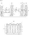
- Figs. 2a -d show schematic representations of a device 100 according to an exemplary embodiment of the present invention.
- the device 100 is an actuator device.
- the principle concept of the present invention more generally relates to shifting a fluid within a fluid channel so that it is not necessary that the device 100 comprises all components essential for an actuator.
- the device 100 may merely relate to a fluid shifting device, the basic concept of the present invention is described in view of using this concept for an actuator and particularly a tactile display.
- the fluid shifting device 100 comprises an actuation channel 20 comprising at least one chamber 15. Each chamber is filled with a fluid or carrier liquid 12 comprising an electrolyte and having at least two inlets 17.
- the carrier liquid 12 is provided by a shift channel 10 (also referred to as main channel).
- the carrier liquid 12 may be provided by pumping the liquid 12 from the shift channel 10 into the actuation channel 20.
- an (external) pump which is indicated in Fig. 2b by reference sign P, may be used.
- the device 100 comprises a sealing control element 13 being enclosed in the carrier liquid 12 of the actuation channel 20 for sealing the at least one chamber 15 and controlling a shift of the liquid 12 within the actuation channel 20 in response to a control signal 30.
- the status of the control signal 30, i.e., whether the control signal is switched on or off, is indicated in Figs. 2a-d by "on" and "off".
- the control signal is applied to at least one pair of electrodes which are not explicitly shown in Figs. 2a-d .
- the at least one pair of electrodes is arranged such that the electrodes are in fluidic contact with the at least one chamber 15 for causing, in response to the control signal 30, an electrocapillary force acting on the sealing control element 13, see Figs. 4a-e and 5a-d .
- each inlet 17 has a cross-section which is smaller than a cross-section of the at least one chamber 15.
- the sealing control element 13 has a surface tension which is higher than a surface tension of the carrier liquid 12, such that in the absence of the control signal 30 the sealing control element 13 is trapped in one of the at least one chamber 15 due to an intrinsic capillary force.
- the device 100 comprises two chambers 15, wherein each chamber 15 has two inlets 17.
- the sealing control element 13 is trapped in one of the two chambers 15 (namely in the lower one of the two chambers), and in Fig.
- the sealing control element 13 is trapped in the other one of the two chambers 15 (namely in the upper one of the two chambers). If the sealing control element 13 is located and/or trapped in one of the chambers 15, it seals the chamber in which it is located and/or trapped. In such a situation or state, the actuation channel 20 is closed, since no fluid or liquid can pass the sealed channel.
- the device 100 comprises an elastic membrane 6 which is arranged at an end portion of the device 100 and which seals a corresponding end portion of the actuation channel 20.
- the elastic membrane 6 serves as actuating element which is actuated by a shift of the fluid 12 within the actuation channel 20.
- FIG. 1 illustrates a distinct state of the device 100 in order to describe the basic principle of the present invention.
- the basic principle combines three components: capillary barriers (realized by inlets 17), external triggers (realized by control signal 30) and a segmented flow (realized by sealing control element 13).
- a single actuator 100 comprises an actuator channel 20 which is sealed with an elastic membrane 6.
- the actuator channel 20 branches off from one main microfluidic channel 10 from which and into which liquid 12 can be probed by a single (syringe) pump P (i.e., one pump operates all actuators 100).
- the actuator channel 20 is subdivided into discreet chambers 15 interconnected by capillary barriers 17.
- the chambers 15 are designed such that capillary forces are negligible, i.e., with larger diameters than the capillary barriers 17. Further, immiscible plugs 13 are inserted into the carrier liquid 12 thus forming a segmented flow. Each actuator channel 20 features one of these plugs 13 which are generated in a suitable microfluidic structure located further up along the main channel 10.
- the sealing control element (immiscible plug) 13 is preferably made from a liquid with high surface tension and low viscosity.
- liquid metals may be used as sealing control element 13 because liquid metals have high surface tensions (several 100 mN/m, at least an order of magnitude greater than water) and very low viscosities, usually in the range of water (a few mPa ⁇ s). This means that they will experience large positive capillary pressure when entering a microchannel, but once they penetrate the channel, they will flow readily due to their low viscosity.
- the sealing control element 13 is located in the first chamber 15 along the actuator channel 20. It is trapped between the two capillary barriers 17 sealing the chamber 15. This is the stable off-state of the actuator 100 (membrane not deflected, 2a).
- the actuator is then switched by an external trigger (control signal 30) which locally changes the wetting behavior of the sealing control element 13 inside the capillary barrier 17 from non-wetting to wetting.
- control signal 30 an external trigger which locally changes the wetting behavior of the sealing control element 13 inside the capillary barrier 17 from non-wetting to wetting.
- the non-wetting behavior is characterized by a contact angle of ⁇ > 90°
- the wetting behavior is characterized by a contact angle of ⁇ ⁇ 90°.
- the sealing control element 13 Due to this change in the wetting behavior of the sealing control element 13, the sealing control element 13 can enter the capillary barrier 17 and move from the first (lower) to the second (upper) chamber 15, see Fig. 2b , thereby shifting a volume ⁇ V of the fluid 12 within the fluid channel 20 and deforming the elastic membrane 6.
- the wetting behavior of the sealing control element 13 inside the capillary barrier 17 changes again from wetting to non-wetting.
- the sealing control element 13 is trapped in the second (upper) chamber 15, see Fig. 2c .
- the elastic membrane 6 is elongated and forms an elevation which is detectable by a finger 40.
- a taxel can be defined and/or set, wherein the taxel has a distinct value (in form of a distinct height of the elastic membrane 6) as shown in Figs. 2a and 2c , respectively.
- the external trigger control signal 30
- the wetting behavior of the sealing control element 13 inside the capillary barrier 17 changes again from non-wetting to wetting, thereby opening the capillary barrier 17 (gate) again (i.e. the sealing control element 13 can enter the capillary barrier 17 again).
- the sealing control element 13 moves from the second (upper) chamber to the first (lower) chamber, see Fig. 2d .
- the pump may pump out a volume ⁇ V of the fluid 12 from the shift channel 10 and thus the fluid channel 20, i.e., a negative ⁇ V and thus a suction may be applied and/or caused by means of the pump.
- the stable off-state as shown in Fig. 2a , is reached again.
- each device 100 is in fluidic contact with a common shift channel 10.
- the plurality of devices 100 are arranged in a row or a matrix, thereby forming a tactile display 200.
- the tactile display 100 may be controlled by an external control unit.
- the tactile display 200 may comprise a control unit for applying control signals 30 to the electrodes 8 of each of the plurality of devices 100.
- the tactile display may comprise a pump for pumping fluid 12 from the shift channel 10 into the actuator channels 20 of the actuators 100.
- each actuator device 100 can be controlled individually by means of a corresponding control signal (not explicitly shown in Fig. 2e ), i.e., for each actuator device 100, a position of the sealing control element 13 within the actuator channel 20 can be adjusted individually. Depending on this position, each actuator 100 defines a distinct taxel value.
- a change of the wetting behavior of the plug 13 inside the capillary barrier 17 from non-wetting to wetting can be accomplished by several mechanisms, all of which change the surface tension forces in the carrier/plug/surface interface.
- two main effects can be used: continuous electrowetting (CEW) and electrowetting-on-dielectrics (EWOD).
- CEW and EWOD are two effects based on electrocapillarity (EC), i.e., the electrostatic control of the solid/fluid interfacial tension in a microchannel which induces an electrocapillary pressure (ECP) that eventually surpasses the positive capillary pressure (see Fig. 2b ).
- ⁇ is the surface tension of a liquid (e.g. the plug or sealing control element 13)
- d is the diameter of a capillary (e.g. the capillary barrier or inlet 17) and ⁇ denotes the contact angle.
- l is the length of the capillary (e.g. the capillary barrier or inlet 17)
- d is the diameter of the capillary
- A is the cross-sectional area of the capillary
- V is the volume of the capillary
- ⁇ ⁇ is a change in the surface tension of a liquid (e.g. the plug or sealing control element 13)
- ⁇ 0 is the vacuum permittivity
- ⁇ r is the relative permittivity of the liquid.
- the capillary barriers or gates 17 effectively fulfill their purpose.
- the electrocapillary pressure p ECP equals or exceeds the positive capillary pressure p CAP , the gate can be opened.
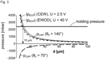
- Fig. 3 shows the acting forces as a function of the channel diameter d as well as the required holding pressure during tactile reading.
- the positive capillary pressure p CAP and the electrocapillary pressure p ECP are calculated according to Eq. 1 and Eq. 2 for CEW and EWOD (50 nm parylene C as dielectric layer) using Galinstan as liquid.
- the electrocapillary pressure p ECP is shown in Fig. 3 as absolute values which acts in opposite direction to the positive capillary pressure p CAP .
- the capillary gate is effective closed as the positive capillary pressure p CAP exceeds the forces on the actuator 100.
- the electrocapillary pressure p ECP exceeds the positive capillary pressure p CAP .
- the liquid metal plug 13 can be moved via pressure applied in the shift channel 10 over the capillary barrier 17 into the next discreet chamber 15, thereby displacing the actuator 100 by one actuator increment i (see Fig. 2c ), bulging the membrane 6 and thus defining and/or setting the taxel.
- the external trigger 30 is then removed, the wetting behavior in the capillary barrier 17 switches back from wetting to non-wetting which again locks the plug 13 in place ( Fig. 2c ). This is the stable on-state of the actuator 100. Reversing to the off-state is performed by reversing this operation ( Fig. 2d ): The external trigger 30 removes the capillary barrier 17, the plug 13 moves (either self-propelling or driven by the relaxation force of the membrane 6 or suction applied via the pump P) back into the lower chamber 15 where it is again locked in place.
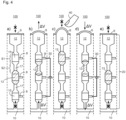
- Figs. 4a -e illustrate the "ratched-lock mode”
- Figs. 5a -d illustrate the "slide-lock mode”.
- the sealing control element 13 e.g. a liquid metal
- the sealing control element 13 is moved along a fluid channel 20 which has a periodic structuring comprising segments S1 and S2 with low (S1) and high (S2) positive capillary pressure, the first segments S1 serving as discrete “ratchet chambers” (chambers 15) and the latter segments S2 serving as "capillary gates” (inlets 17).
- Electrodes 8 are arranged such that an individually addressable set of electrodes can be operated to locally open a single capillary barrier or gate 17.
- a set of electrodes 8 is arranged such that they can actuate the liquid metal plug (sealing control element 13) across each of the capillary gates (inlets 17).
- the immiscible liquid metal plug 13 is entrapped in one of the ratchet chambers 15 located along the actuator channel 20.
- Ratchet chambers 15 are sections S1 of low positive capillary pressure along this actuator channel 20 intersected by sections S2 of high positive capillary pressure which act as a capillary gate.
- Electrodes 8 are arranged such that the liquid metal plug 13 can be moved across each barrier individually. The actuation proceeds from a common shift channel 10. If no electrodes 8 are actuated, i.e.
- Resetting the taxel proceeds likewise due to the back-driving force and/or pressure exerted by the expanded membrane 6 (see Figs. 4d and 4e ).
- resetting the taxel may be achieved in a self-propelling manner.
- resetting the taxel may be achieved by pumping a distinct volume ⁇ V of fluid 12 out of the shift channel 10 and thus out of the fluid channel 20, i.e. by a suction applied via the pump.
- the device 100 comprises three chambers 15, wherein each chamber 15 has two inlets 17.
- the sealing control element or plug 13 is trapped in one of the three chambers 15.
- the sealing control element 13 and the control signal 30 are configured such that the surface tension of the sealing control element 13 is reduced in the presence of the control signal 30 and increased again to its previous value in the absence of the control signal 30.
- the device 100 is configured to switch from a first stable state (e.g. an off- or on-state) to a second stable state (e.g. an on- or off-state) in response to the control signal 30.
- a first stable state e.g. an off- or on-state
- a second stable state e.g. an on- or off-state
- the sealing control element 13 is displaced along a longitudinal axis of the fluid channel 20 from a first chamber to a second chamber in response to the control signal 30.
- the ratchet-lock configuration is challenging to fabricate as the channel shaping needs to be distinctively precise and the control electronics is complex as many electrode pairs need to be actuated.
- the actuation channels 20 must be sufficiently long to accommodate the total volume required for taxel actuation which means, it must be sufficiently long. Given that a single taxel requires several microliters for maximum actuation, at the required small dimension of the microchannels, the actuation channel 20 must be several cm in length which makes the manufacturing of actuator arrays significantly more challenging.
- the liquid metal plug (sealing control element 13) operates perpendicular to the actuator channel 20 and seals it similarly to a sliding lock.
- the main actuation is performed by the same shift mechanism as in the ratchet-lock mode described above.
- the slide-lock configuration only requires the sealing control element 13 to move for very small distances and requires only one pair of electrodes 8 per actuator, thus making the whole configuration significantly simpler in setup compared to the ratchet-lock mode.
- the setting of taxels to arbitrary heights, e.g., for encoding greyscale is very easy in this mode as the discrete positional locking of the ratchet mode does not apply here.
- the ratchet mode if a greyscale value is to be encoded, another ratchet chamber 15, a capillary barrier 17 as well as another set of electrodes 8 need to be added per discrete position of the taxel.
- the slide-lock mode is continuous as the positional setting of the taxel is controlled via the shift channel solely.
- a portion of the immiscible liquid metal plug 13 is attracted by and entrapped in a circular chamber 15 which has the electrodes 8 connected in two dead-end channels left and right. Due to the shaping of the channel, the liquid metal plug 13 is continuously pushed into the chamber 15 and thus seals the actuator channel 20.
- the shift channel 10 operates perpendicular to it. If the electrodes 8 are not actuated, i.e., if no control signal 30 (voltage U) is applied to the electrodes 8 (see Fig. 5a ), the plug 13 seals the chamber 15 and thus locks the taxel. In Fig. 5a , the taxel is in a flat (off-)state.
- the deformation or elongation of the membrane 6 may be abolished in a self-propelling manner. Further alternatively or in addition, the deformation or elongation of the membrane 6 may be abolished by pumping a distinct volume ⁇ V of fluid 12 out of the shift channel 10 and thus out of the fluid channel 20, i.e. by a suction applied via the pump. Subsequently removing the control signal 30 (voltage U) closes the chamber 15 again and thus locks the taxel to the initial state (off-state) of Fig. 5a .
- the chamber 15 has a circular shape in the example shown in Figs. 5a-d
- the chamber 15 may alternatively have a different shape which is suitable to lock the fluid channel 20.
- the chamber 15 may be formed as the crossing of the inlets 17. Accordingly, the chamber 15 may have a cruciform shape and/or a cruciform cross section.
- the device 100 of Figs. 6a-d works similar to the device 100 of Figs. 5a-d . If the electrodes 8 are not actuated, i.e., if no control signal 30 (voltage U) is applied to the electrodes 8 (see Fig. 6a ), the plug 13 is attracted by the chamber 15 due to capillary forces.
- the plug 13 Due to its position in this state, the plug 13 seals the chamber 15 and thus locks the taxel.
- the taxel is in a flat (off-)state.
- Applying a voltage U (control signal 30) across the electrodes 8 moves or withdraws the liquid metal 13 perpendicular to the fluid channel 20, thus moving it at least partly out of the way similarly to a sliding lock. This allows the pressure from the shift channel 10 to actuate the taxel.
- the plug 13 moves back to the crossing of the inlets 17 and closes the chamber 15, thereby setting the taxel to an elongated (on-)state (see Fig. 6c ). Resetting the taxel proceeds likewise.
- the deformation or elongation of the membrane 6 may be abolished by pumping a distinct volume ⁇ V of fluid 12 out of the shift channel 10 and thus out of the fluid channel 20, i.e. by a suction applied via the pump. Subsequently removing the control signal 30 (voltage U) closes the chamber 15 again and thus locks the taxel to the initial state (off-state) of Fig. 6a .
- the device 100 comprises only one chamber 15 having at least two inlets 17.
- a control signal 30 In the absence of a control signal 30, at least a portion of the sealing control element 13 is trapped in said chamber 15.
- the sealing control element 13 and the control signal 30 are configured such that the surface tension of the sealing control element 13 is reduced in the presence of the control signal 30 and increased again to its previous value in the absence of the control signal 30.
- the device 100 is configured to switch from a first stable state (e.g. an off- or on-state) to a second stable state (e.g. an on- or off-state) in response to the control signal 30.
- the sealing control element 13 is displaced orthogonal to the longitudinal axis of the fluid channel 20 in response to the control signal 30, thereby enabling the fluid 12 to enter and/or pass the chamber 15 along the longitudinal axis of the fluid channel 20.
- microactuators The relevant scientific state-of-the-art is the field of microactuators.
- many of the required properties are problematic for classical microactuators.
- a 1.4 mm pitch which is required for tactile displays is significantly smaller than the lateral size of most microactuators.
- Even if the core components of microactuators are microscopic in scale, they often require bulky external components (magnets, springs, fixtures) making them unsuitable for high-density integration.
- microactuators do not support a 100 mN holding force, as required for tactile displays, and actuator strokes in the range of 0.5 mm are challenging. If a bistable (latchable) microactuator is sought, the choice is further restricted.
- actuators In terms of high-density integration, many actuators suffer from the fact that they require hybrid manufacturing processes, manual assembly or specialized and expensive materials. Even if an actuator allows dense integration the required bulky external components, e.g., for generating high magnetic or electric fields, prevent it.
- microactuators In general, current state-of-the-art microactuators always compromise between the most important parameters: actuator stroke, stability, integration density, costs and lateral size. In improving one property, one usually degrades another. As an example, if the actuator stroke must be increased, stronger and bulkier components usually have to be used, thus increasing size and decreasing integration density.
- the only microactuators for which high-density integration has been demonstrated are the electrostatic actuators which drive digital micromirror devices (DMDs). However, these actuators only achieve a few ⁇ m of actuator stroke and possess virtually no holding force.
- microfluidics large-scale integration (MLSI) based on pneumatic membrane valves developed by the Quake group has been discussed as an option for tactile displays, see M. A. Unger, H. P.
- MLSI is designed as microfluidic valve platform which miniaturizes only the actual valve but not the actuator itself.
- the Quake valves require macroscopic external pneumatic valves for actuation.
- MLSI makes use of (de-)multiplexing concepts which does not allow setting the on-chip valves individually and in parallel.
- thermal actuator arrays with up to 588 individually addressable as well as bistable valves based on phase-change materials have been developed, see C. Richter, K. Gambheimer et al., Microfluid. Nanofluid., 20, 130 (2016 ). However these concepts were too slow for the use in tactile displays.
- Fig. 7 lists noteworthy attempts for setting up tactile displays by using known microactuator concepts.
- Piezoactuators have been among the first actuators used for tactile displays, see H. Hernandez, E. Preza et al., Electronics, Robotics and Automotive Mechanics Conference, 2009. CERMA'09., 402 (2009 ). Even though they are the de facto standard in commercial Braille lines and tactile displays, they are too expensive, not bistable and thus unsuitable for mobile tactile displays. Similar to MLSI, pneumatic actuation prohibits dense integration and usually yields taxels of insufficient mechanical stability, see X. Wu, H. Zhu et al., TRANSDUCERS 2007-2007 International Solid-State Sensors, Actuators and Microsystems Conference, 1409 (2007 ).
- Electroactive polymers which make use of the piezoelectric properties of certain polymers have been studied as an alternative means to generate taxel actuators. However, due to fact that they require extremely high electric fields, they have proven unsuitable for high-density integration, see H. S. Lee, H. Phung et al., Sensors and Actuators A: Physical, 205, 191 (2014 ). Actuators based on thermopneumatic actuators yield taxels of inferior mechanical stability as do shape-memory alloys and shape-memory polymers, see J. S. Lee und S. Lucyszyn, Journal of Microelectromechanical Systems, 14, 673 (2005 ) and T. Matsunaga, K.
- each of the conventional actuator concepts has drawbacks so that these conventional actuator concepts do not provide all properties that are required for a tactile display. With the concept provided within the present invention, however, these drawbacks have been overcome.
- an actuator which is based on the concept of the present invention may have a number of unique features which make it a ground-breaking novel concept for fundamental research and specifically for large-scale tactile displays:
Landscapes
- Engineering & Computer Science (AREA)
- Theoretical Computer Science (AREA)
- General Physics & Mathematics (AREA)
- Physics & Mathematics (AREA)
- General Engineering & Computer Science (AREA)
- Audiology, Speech & Language Pathology (AREA)
- Educational Administration (AREA)
- Educational Technology (AREA)
- Health & Medical Sciences (AREA)
- Business, Economics & Management (AREA)
- General Health & Medical Sciences (AREA)
- Human Computer Interaction (AREA)
- Micromachines (AREA)
- User Interface Of Digital Computer (AREA)
- Position Input By Displaying (AREA)
- Manipulator (AREA)
- Actuator (AREA)
Claims (14)
- Eine Fluidverschiebungsvorrichtung (100), die Folgendes umfasst:- einen Fluidkanal (20), der mindestens eine Kammer (15) umfasst, wobei jede Kammer (15) mit einem Fluid (12) gefüllt ist, das einen Elektrolyten umfasst, und mindestens zwei Einlässe (17) aufweist, wobei jeder Einlass (17) einen Querschnitt aufweist, der kleiner als ein Querschnitt der mindestens einen Kammer (15) ist;- ein Dichtungssteuerelement (13), das vom Fluid (12) des Fluidkanals (20) umschlossen ist, um die mindestens eine Kammer (15) abzudichten und in Reaktion auf ein Steuersignal (30) eine Verschiebung des Fluids (12) innerhalb des Fluidkanals (20) zu steuern; und- mindestens ein Paar Elektroden (8), die so angeordnet sind, dass die Elektroden (8) in Fluidkontakt mit der mindestens einen Kammer (15) stehen, um in Reaktion auf das Steuersignal (30) eine elektrokapillare Kraft zu bewirken, die auf das Dichtungssteuerelement (13) wirkt;wobei das Dichtungssteuerelement (13) eine Oberflächenspannung aufweist, die höher ist als eine Oberflächenspannung des Fluids (12), sodass in Abwesenheit des Steuersignals (30) mindestens ein Teil des Dichtungssteuerelements (13) in einer der mindestens einen Kammer (15) aufgrund einer intrinsischen Kapillarkraft eingeschlossen bzw. gefangen ist (trapped), wodurch die genannte eine der mindestens einen Kammer (15) abgedichtet wird.
- Die Vorrichtung (100) nach Anspruch 1, wobei das Dichtungssteuerelement (13) ein Fluidsegment ist, das mit dem Fluid (12) unmischbar ist.
- Die Vorrichtung (100) nach irgendeinem der vorstehenden Ansprüche, wobei die Vorrichtung (100) konfiguriert ist, um in Reaktion auf das Steuersignal (30) von einem ersten stabilen Zustand in einen zweiten stabilen Zustand umzuschalten, wobei das Dichtungssteuerelement (13) und das Steuersignal (30) so konfiguriert sind, dass die Oberflächenspannung des Dichtungssteuerelements (13) bei Anwesenheit des Steuersignals (30) verringert und bei Abwesenheit des Steuersignals (30) wieder auf ihren vorherigen Wert erhöht wird.
- Die Vorrichtung (100) nach irgendeinem der vorstehenden Ansprüche, wobei in Reaktion auf das Steuersignal (30)das Dichtungssteuerelement (13) entlang einer Längsachse des Fluidkanals (20) von einer ersten Kammer zu einer zweiten Kammer verschoben wird, oderdas Dichtungssteuerelement (13) orthogonal zur Längsachse des Fluidkanals (20) verschoben wird, wodurch es dem Fluid (12) ermöglicht wird, entlang der Längsachse des Fluidkanals (20) in die mindestens eine Kammer (15) einzutreten und/oder diese zu passieren.
- Die Vorrichtung (100) nach irgendeinem der vorstehenden Ansprüche, die ferner Folgendes umfasst:- eine Pumpe (P) zum Pumpen von Fluid in den Fluidkanal (20).
- Die Vorrichtung (100) nach irgendeinem der vorstehenden Ansprüche, wobei ein Endabschnitt des Fluidkanals (20) mit einer elastischen Membran (6) verschlossen ist, und
wobei insbesondere die elastische Membran (6) ein Betätigungselement ist, der Fluidkanal (20) ein Betätigungskanal ist und die Vorrichtung (100) ein bistabiles Betätigungselement ist. - Eine Verwendung der Vorrichtung (100) nach irgendeinem der vorstehenden Ansprüche für eine taktile Anzeige (200), wobei ein Taxel durch Verschieben des Fluids (12) im Fluidkanal (20) definiert ist.
- Eine taktile Anzeige (200), die Folgendes umfasst:- eine Vielzahl von Vorrichtungen (100) nach irgendeinem der Ansprüche von 1 bis 6, wobei die Vorrichtungen (100) in einer Reihe oder einer Matrix angeordnet sind, und wobei jede der Vielzahl von Vorrichtungen (100) in Fluidkontakt mit einem Verschiebungskanal (10) steht, der jeder der Vielzahl von Vorrichtungen (100) Fluid (12) zuführt.
- Die taktile Anzeige (200) nach Anspruch 8, die ferner Folgendes umfasst:- eine Steuereinheit zum Anlegen von Steuersignalen (30) an die Elektroden (8) einer jeden der Vielzahl von Vorrichtungen (100).
- Die taktile Anzeige (200) nach Anspruch 8 oder 9, die ferner Folgendes umfasst:- eine Pumpe (P) zum Pumpen des Fluids (12) in jeden Fluidkanal (20) der Vielzahl von Vorrichtungen (100), wobei die Pumpe (P) vorzugsweise eine einzelne Spritzenpumpe ist.
- Ein Verfahren zum Verschieben eines Fluids (12) innerhalb eines Fluidkanals (20) mittels eines Steuersignals (30), wobei der Fluidkanal (20) mindestens eine Kammer (15) umfasst, wobei jede Kammer (15) mindestens zwei Einlässe (17) aufweist und mit einem Fluid (12) gefüllt ist, das einen Elektrolyten umfasst, wobei jeder Einlass (17) einen Querschnitt aufweist, der kleiner ist als ein Querschnitt der mindestens einen Kammer (15), und wobei in Abwesenheit des Steuersignals (30), zumindest ein Teil eines Dichtungssteuerelements (13), das vom Fluid (12) des Fluidkanals (20) umschlossen ist, um die mindestens eine Kammer (15) abzudichten und eine Verschiebung des Fluids (12) innerhalb des Fluidkanals (20) in Reaktion auf das Steuersignal (30) zu steuern, in einer der mindestens einen Kammer (15) aufgrund einer intrinsischen Kapillarkraft eingeschlossen bzw. gefangen ist (trapped), wodurch die genannte eine von der mindestens einen Kammer (15) abgedichtet wird, wobei das Dichtungssteuerelements (13) eine Oberflächenspannung aufweist, die höher ist als eine Oberflächenspannung des Fluids (12), wobei das Verfahren umfasst:- Anlegen des Steuersignals (30) an oder zwischen (on or across) ein Paar von Elektroden (8), die in Fluidkontakt mit der mindestens einen Kammer (15) stehen, wodurch eine elektrokapillare Kraft bewirkt wird, die auf das Dichtungssteuerelement (13) wirkt.
- Das Verfahren nach Anspruch 11,wobei das angelegte Steuersignal (30) so konfiguriert ist, dass die durch das Steuersignal (30) verursachte elektrokapillare Kraft der intrinsischen Kapillarkraft entgegenwirkt und größer ist als die intrinsische Kapillarkraft, sodass sich das Dichtungssteuerelement (13) als Reaktion auf das Steuersignal (30) zumindest teilweise aus der genannten einen der mindestens einen Kammer (15) herausbewegt, wodurch eine Verschiebung des Fluids (12) innerhalb des Fluidkanals (20) ermöglicht wird, und/oderwobei das angelegte Steuersignal (30) so konfiguriert ist, dass es eine Oberflächenspannung des Dichtungssteuerelements (13) verringert.
- Das Verfahren nach Anspruch 11 oder 12, wobei die Verschiebung des Fluids (12) selbsttreibend und/oder durch Pumpen von Fluid (12) in den und/oder aus dem Fluidkanal (20) erfolgt.
- Das Verfahren nach irgendeinem der Ansprüche von 11 bis 13, das ferner Folgendes umfasst:- Definieren eines Taxels durch Verschieben des Fluids (12) innerhalb des Fluidkanals (20).
Priority Applications (8)
| Application Number | Priority Date | Filing Date | Title |
|---|---|---|---|
| EP21166147.5A EP4068249B1 (de) | 2021-03-31 | 2021-03-31 | Vorrichtung und verfahren zum verschieben eines fluids in einem fluidkanal, verwendung der vorrichtung und taktile anzeige |
| JP2023560392A JP2024517576A (ja) | 2021-03-31 | 2022-03-25 | 流体チャネル内の流体をシフトさせる装置及び方法、この装置の使用、及び触覚ディスプレイ |
| CA3212777A CA3212777A1 (en) | 2021-03-31 | 2022-03-25 | Device and method for shifting a fluid within a fluid channel, use of the device, and tactile display |
| US18/549,763 US20240153402A1 (en) | 2021-03-31 | 2022-03-25 | Device and Method for Shifting a Fluid within a Fluid Device Channel, Use of the Device, and Tactile Display |
| KR1020237036526A KR20230159595A (ko) | 2021-03-31 | 2022-03-25 | 유체 채널 내의 유체를 변위시키는 장치 및 방법, 이 장치의 용도, 및 촉각 디스플레이 |
| PCT/EP2022/057858 WO2022207472A1 (en) | 2021-03-31 | 2022-03-25 | Device and method for shifting a fluid within a fluid channel, use of the device, and tactile display |
| CN202280025466.XA CN117157689A (zh) | 2021-03-31 | 2022-03-25 | 用于在流体通道内使流体移位的装置和方法、装置的用途以及触觉显示器 |
| AU2022248402A AU2022248402B2 (en) | 2021-03-31 | 2022-03-25 | Device and method for shifting a fluid within a fluid channel, use of the device, and tactile display |
Applications Claiming Priority (1)
| Application Number | Priority Date | Filing Date | Title |
|---|---|---|---|
| EP21166147.5A EP4068249B1 (de) | 2021-03-31 | 2021-03-31 | Vorrichtung und verfahren zum verschieben eines fluids in einem fluidkanal, verwendung der vorrichtung und taktile anzeige |
Publications (2)
| Publication Number | Publication Date |
|---|---|
| EP4068249A1 EP4068249A1 (de) | 2022-10-05 |
| EP4068249B1 true EP4068249B1 (de) | 2024-10-09 |
Family
ID=75339450
Family Applications (1)
| Application Number | Title | Priority Date | Filing Date |
|---|---|---|---|
| EP21166147.5A Active EP4068249B1 (de) | 2021-03-31 | 2021-03-31 | Vorrichtung und verfahren zum verschieben eines fluids in einem fluidkanal, verwendung der vorrichtung und taktile anzeige |
Country Status (8)
| Country | Link |
|---|---|
| US (1) | US20240153402A1 (de) |
| EP (1) | EP4068249B1 (de) |
| JP (1) | JP2024517576A (de) |
| KR (1) | KR20230159595A (de) |
| CN (1) | CN117157689A (de) |
| AU (1) | AU2022248402B2 (de) |
| CA (1) | CA3212777A1 (de) |
| WO (1) | WO2022207472A1 (de) |
Families Citing this family (1)
| Publication number | Priority date | Publication date | Assignee | Title |
|---|---|---|---|---|
| WO2026016038A1 (en) * | 2024-07-16 | 2026-01-22 | Westlake University | A control system for an array of 3d shape-morphing units and a 3d shape-morphing system |
Family Cites Families (12)
| Publication number | Priority date | Publication date | Assignee | Title |
|---|---|---|---|---|
| GB2212336A (en) * | 1987-11-10 | 1989-07-19 | Gen Electric Co Plc | Liquid displacement |
| EP1490601B1 (de) | 2002-03-23 | 2007-08-15 | Starbridge Systems Limited | Mikromechanische bauelemente |
| CN100550593C (zh) * | 2002-06-19 | 2009-10-14 | 皇家飞利浦电子股份有限公司 | 触觉装置 |
| EP1519212A1 (de) * | 2003-09-27 | 2005-03-30 | 3M Innovative Properties Company | Anzeigevorrichtung zum irreversiblen Umschalten aus einem ersten in einen zweiten Zustand |
| TWI479195B (zh) * | 2007-09-12 | 2015-04-01 | Univ Cincinnati | 電流體裝置、視覺顯示器及製造與操作該等電流體裝置之方法 |
| US8551599B2 (en) | 2008-09-03 | 2013-10-08 | The Regents Of The University Of Michigan | Reconfigurable microactuator and method of configuring same |
| EP2406783B1 (de) * | 2009-03-12 | 2016-02-10 | Creator Technology B.V. | Elektrofluidische anzeigevorrichtung |
| US8508468B2 (en) * | 2009-05-29 | 2013-08-13 | Creator Technology B.V. | Display apparatus comprising electrofluidic cells driven based on calculated charge corresponding to current and new pixel cell display properties |
| FR2955404B1 (fr) | 2010-01-18 | 2012-01-27 | Commissariat Energie Atomique | Actionneur fluidique et dispositif d'affichage a actionneurs fluidiques |
| DE102012005992B3 (de) | 2012-03-23 | 2013-07-11 | Karlsruher Institut für Technologie | Bistabiler Aktor, Aktoranordnung, Verfahren zum Aktuieren und Verwendung |
| WO2016205375A1 (en) * | 2015-06-18 | 2016-12-22 | The Regents Of The University Of Michigan | Microfluidic actuators with integrated addressing |
| US11198128B2 (en) * | 2018-09-05 | 2021-12-14 | International Business Machines Corporation | Microfluidic device with array of chambers for encoding detectable information |
-
2021
- 2021-03-31 EP EP21166147.5A patent/EP4068249B1/de active Active
-
2022
- 2022-03-25 WO PCT/EP2022/057858 patent/WO2022207472A1/en not_active Ceased
- 2022-03-25 US US18/549,763 patent/US20240153402A1/en active Pending
- 2022-03-25 AU AU2022248402A patent/AU2022248402B2/en active Active
- 2022-03-25 JP JP2023560392A patent/JP2024517576A/ja active Pending
- 2022-03-25 KR KR1020237036526A patent/KR20230159595A/ko not_active Ceased
- 2022-03-25 CN CN202280025466.XA patent/CN117157689A/zh active Pending
- 2022-03-25 CA CA3212777A patent/CA3212777A1/en active Pending
Also Published As
| Publication number | Publication date |
|---|---|
| WO2022207472A1 (en) | 2022-10-06 |
| EP4068249A1 (de) | 2022-10-05 |
| CN117157689A (zh) | 2023-12-01 |
| US20240153402A1 (en) | 2024-05-09 |
| AU2022248402A1 (en) | 2023-08-31 |
| AU2022248402B2 (en) | 2024-08-15 |
| KR20230159595A (ko) | 2023-11-21 |
| JP2024517576A (ja) | 2024-04-23 |
| CA3212777A1 (en) | 2022-10-06 |
Similar Documents
| Publication | Publication Date | Title |
|---|---|---|
| EP1597716B1 (de) | Elektroaktive polymer-betätigungsglied-braille-zelle und braille-anzeige | |
| Khoshmanesh et al. | Liquid metal enabled microfluidics | |
| US20070229233A1 (en) | Reconfigurable tactile-enhanced display including "tap-and-drop" computing system for vision impaired users | |
| Wang et al. | Digital microfluidic operations on micro-electrode dot array architecture | |
| AU2022248402B2 (en) | Device and method for shifting a fluid within a fluid channel, use of the device, and tactile display | |
| EP1518315A1 (de) | Tastvorrichtung | |
| Chae et al. | 3D electrowetting-on-dielectric actuation | |
| Cho et al. | Splitting a liquid droplet for electrowetting-based microfluidics | |
| JP2008517250A (ja) | コンピュータを用いた微少流体制御方法およびシステム並びにこれに用いるコンピュータプログラム製品 | |
| US20070020589A1 (en) | Electrothermal refreshable Braille cell and method for actuating same | |
| Yang et al. | Development of a miniature tunable stiffness display using MR fluids for haptic application | |
| Han et al. | HapBead: on-skin microfluidic haptic Interface using tunable bead | |
| Sadeghi et al. | Electrostatic micro-hydraulic systems | |
| Piyasena et al. | Electroosmotically driven microfluidic actuators | |
| Abe et al. | Droplet μTAS using electro-conjugate fluid—feedback position control of multiple droplets in flow channel matrix | |
| Kohl | Fluidic actuation by electrorheological microdevices | |
| CN100506685C (zh) | 利用磁性液滴的微通道流体驱动方法 | |
| Fouillet et al. | EWOD digital microfluidics for Lab on a Chip | |
| DE102019108971B4 (de) | Displaysystem, Touchscreen mit Displaysystem sowie Verfahren zum Betrieb eines Displaysystems und Computerprogrammprodukt | |
| Lee | Microactuation by continuous electrowetting and electrowetting: Theory, fabrication, and demonstration | |
| Berthier et al. | Modeling microdrop motion between covered and open regions of EWOD microsystems | |
| CN104112372A (zh) | 一种盲文电子书 | |
| Baroud | Droplet Microfluidics in Two-Dimensional Channels | |
| Paneri et al. | Effect of change in ratio of electrode to total pitch length in EWOD based microfluidic system | |
| Yunus et al. | Effect of applied voltage on a new designed lab on a chip electrowetting actuation system |
Legal Events
| Date | Code | Title | Description |
|---|---|---|---|
| PUAI | Public reference made under article 153(3) epc to a published international application that has entered the european phase |
Free format text: ORIGINAL CODE: 0009012 |
|
| STAA | Information on the status of an ep patent application or granted ep patent |
Free format text: STATUS: THE APPLICATION HAS BEEN PUBLISHED |
|
| AK | Designated contracting states |
Kind code of ref document: A1 Designated state(s): AL AT BE BG CH CY CZ DE DK EE ES FI FR GB GR HR HU IE IS IT LI LT LU LV MC MK MT NL NO PL PT RO RS SE SI SK SM TR |
|
| STAA | Information on the status of an ep patent application or granted ep patent |
Free format text: STATUS: REQUEST FOR EXAMINATION WAS MADE |
|
| 17P | Request for examination filed |
Effective date: 20230330 |
|
| RBV | Designated contracting states (corrected) |
Designated state(s): AL AT BE BG CH CY CZ DE DK EE ES FI FR GB GR HR HU IE IS IT LI LT LU LV MC MK MT NL NO PL PT RO RS SE SI SK SM TR |
|
| GRAP | Despatch of communication of intention to grant a patent |
Free format text: ORIGINAL CODE: EPIDOSNIGR1 |
|
| STAA | Information on the status of an ep patent application or granted ep patent |
Free format text: STATUS: GRANT OF PATENT IS INTENDED |
|
| INTG | Intention to grant announced |
Effective date: 20240522 |
|
| GRAS | Grant fee paid |
Free format text: ORIGINAL CODE: EPIDOSNIGR3 |
|
| GRAA | (expected) grant |
Free format text: ORIGINAL CODE: 0009210 |
|
| STAA | Information on the status of an ep patent application or granted ep patent |
Free format text: STATUS: THE PATENT HAS BEEN GRANTED |
|
| AK | Designated contracting states |
Kind code of ref document: B1 Designated state(s): AL AT BE BG CH CY CZ DE DK EE ES FI FR GB GR HR HU IE IS IT LI LT LU LV MC MK MT NL NO PL PT RO RS SE SI SK SM TR |
|
| REG | Reference to a national code |
Ref country code: CH Ref legal event code: EP |
|
| REG | Reference to a national code |
Ref country code: DE Ref legal event code: R081 Ref document number: 602021019770 Country of ref document: DE Owner name: GLASSOMER GMBH, DE Free format text: FORMER OWNER: ANMELDERANGABEN UNKLAR / UNVOLLSTAENDIG, 80297 MUENCHEN, DE Ref country code: DE Ref legal event code: R081 Ref document number: 602021019770 Country of ref document: DE Owner name: ALBERT-LUDWIGS-UNIVERSITAET FREIBURG, KOERPERS, DE Free format text: FORMER OWNER: ANMELDERANGABEN UNKLAR / UNVOLLSTAENDIG, 80297 MUENCHEN, DE |
|
| REG | Reference to a national code |
Ref country code: DE Ref legal event code: R096 Ref document number: 602021019770 Country of ref document: DE |
|
| REG | Reference to a national code |
Ref country code: IE Ref legal event code: FG4D |
|
| REG | Reference to a national code |
Ref country code: LT Ref legal event code: MG9D |
|
| REG | Reference to a national code |
Ref country code: NL Ref legal event code: MP Effective date: 20241009 |
|
| REG | Reference to a national code |
Ref country code: AT Ref legal event code: MK05 Ref document number: 1731455 Country of ref document: AT Kind code of ref document: T Effective date: 20241009 |
|
| PG25 | Lapsed in a contracting state [announced via postgrant information from national office to epo] |
Ref country code: NL Free format text: LAPSE BECAUSE OF FAILURE TO SUBMIT A TRANSLATION OF THE DESCRIPTION OR TO PAY THE FEE WITHIN THE PRESCRIBED TIME-LIMIT Effective date: 20241009 |
|
| PG25 | Lapsed in a contracting state [announced via postgrant information from national office to epo] |
Ref country code: NL Free format text: LAPSE BECAUSE OF FAILURE TO SUBMIT A TRANSLATION OF THE DESCRIPTION OR TO PAY THE FEE WITHIN THE PRESCRIBED TIME-LIMIT Effective date: 20241009 |
|
| PG25 | Lapsed in a contracting state [announced via postgrant information from national office to epo] |
Ref country code: PT Free format text: LAPSE BECAUSE OF FAILURE TO SUBMIT A TRANSLATION OF THE DESCRIPTION OR TO PAY THE FEE WITHIN THE PRESCRIBED TIME-LIMIT Effective date: 20250210 Ref country code: HR Free format text: LAPSE BECAUSE OF FAILURE TO SUBMIT A TRANSLATION OF THE DESCRIPTION OR TO PAY THE FEE WITHIN THE PRESCRIBED TIME-LIMIT Effective date: 20241009 Ref country code: IS Free format text: LAPSE BECAUSE OF FAILURE TO SUBMIT A TRANSLATION OF THE DESCRIPTION OR TO PAY THE FEE WITHIN THE PRESCRIBED TIME-LIMIT Effective date: 20250209 |
|
| PG25 | Lapsed in a contracting state [announced via postgrant information from national office to epo] |
Ref country code: FI Free format text: LAPSE BECAUSE OF FAILURE TO SUBMIT A TRANSLATION OF THE DESCRIPTION OR TO PAY THE FEE WITHIN THE PRESCRIBED TIME-LIMIT Effective date: 20241009 |
|
| PG25 | Lapsed in a contracting state [announced via postgrant information from national office to epo] |
Ref country code: BG Free format text: LAPSE BECAUSE OF FAILURE TO SUBMIT A TRANSLATION OF THE DESCRIPTION OR TO PAY THE FEE WITHIN THE PRESCRIBED TIME-LIMIT Effective date: 20241009 |
|
| PG25 | Lapsed in a contracting state [announced via postgrant information from national office to epo] |
Ref country code: ES Free format text: LAPSE BECAUSE OF FAILURE TO SUBMIT A TRANSLATION OF THE DESCRIPTION OR TO PAY THE FEE WITHIN THE PRESCRIBED TIME-LIMIT Effective date: 20241009 |
|
| PG25 | Lapsed in a contracting state [announced via postgrant information from national office to epo] |
Ref country code: NO Free format text: LAPSE BECAUSE OF FAILURE TO SUBMIT A TRANSLATION OF THE DESCRIPTION OR TO PAY THE FEE WITHIN THE PRESCRIBED TIME-LIMIT Effective date: 20250109 |
|
| PG25 | Lapsed in a contracting state [announced via postgrant information from national office to epo] |
Ref country code: LV Free format text: LAPSE BECAUSE OF FAILURE TO SUBMIT A TRANSLATION OF THE DESCRIPTION OR TO PAY THE FEE WITHIN THE PRESCRIBED TIME-LIMIT Effective date: 20241009 Ref country code: AT Free format text: LAPSE BECAUSE OF FAILURE TO SUBMIT A TRANSLATION OF THE DESCRIPTION OR TO PAY THE FEE WITHIN THE PRESCRIBED TIME-LIMIT Effective date: 20241009 Ref country code: GR Free format text: LAPSE BECAUSE OF FAILURE TO SUBMIT A TRANSLATION OF THE DESCRIPTION OR TO PAY THE FEE WITHIN THE PRESCRIBED TIME-LIMIT Effective date: 20250110 |
|
| PG25 | Lapsed in a contracting state [announced via postgrant information from national office to epo] |
Ref country code: PL Free format text: LAPSE BECAUSE OF FAILURE TO SUBMIT A TRANSLATION OF THE DESCRIPTION OR TO PAY THE FEE WITHIN THE PRESCRIBED TIME-LIMIT Effective date: 20241009 |
|
| PG25 | Lapsed in a contracting state [announced via postgrant information from national office to epo] |
Ref country code: RS Free format text: LAPSE BECAUSE OF FAILURE TO SUBMIT A TRANSLATION OF THE DESCRIPTION OR TO PAY THE FEE WITHIN THE PRESCRIBED TIME-LIMIT Effective date: 20250109 |
|
| PG25 | Lapsed in a contracting state [announced via postgrant information from national office to epo] |
Ref country code: SM Free format text: LAPSE BECAUSE OF FAILURE TO SUBMIT A TRANSLATION OF THE DESCRIPTION OR TO PAY THE FEE WITHIN THE PRESCRIBED TIME-LIMIT Effective date: 20241009 |
|
| PG25 | Lapsed in a contracting state [announced via postgrant information from national office to epo] |
Ref country code: DK Free format text: LAPSE BECAUSE OF FAILURE TO SUBMIT A TRANSLATION OF THE DESCRIPTION OR TO PAY THE FEE WITHIN THE PRESCRIBED TIME-LIMIT Effective date: 20241009 |
|
| REG | Reference to a national code |
Ref country code: DE Ref legal event code: R097 Ref document number: 602021019770 Country of ref document: DE |
|
| PG25 | Lapsed in a contracting state [announced via postgrant information from national office to epo] |
Ref country code: EE Free format text: LAPSE BECAUSE OF FAILURE TO SUBMIT A TRANSLATION OF THE DESCRIPTION OR TO PAY THE FEE WITHIN THE PRESCRIBED TIME-LIMIT Effective date: 20241009 |
|
| PG25 | Lapsed in a contracting state [announced via postgrant information from national office to epo] |
Ref country code: RO Free format text: LAPSE BECAUSE OF FAILURE TO SUBMIT A TRANSLATION OF THE DESCRIPTION OR TO PAY THE FEE WITHIN THE PRESCRIBED TIME-LIMIT Effective date: 20241009 |
|
| PG25 | Lapsed in a contracting state [announced via postgrant information from national office to epo] |
Ref country code: SK Free format text: LAPSE BECAUSE OF FAILURE TO SUBMIT A TRANSLATION OF THE DESCRIPTION OR TO PAY THE FEE WITHIN THE PRESCRIBED TIME-LIMIT Effective date: 20241009 |
|
| PG25 | Lapsed in a contracting state [announced via postgrant information from national office to epo] |
Ref country code: CZ Free format text: LAPSE BECAUSE OF FAILURE TO SUBMIT A TRANSLATION OF THE DESCRIPTION OR TO PAY THE FEE WITHIN THE PRESCRIBED TIME-LIMIT Effective date: 20241009 |
|
| PG25 | Lapsed in a contracting state [announced via postgrant information from national office to epo] |
Ref country code: IT Free format text: LAPSE BECAUSE OF FAILURE TO SUBMIT A TRANSLATION OF THE DESCRIPTION OR TO PAY THE FEE WITHIN THE PRESCRIBED TIME-LIMIT Effective date: 20241009 |
|
| PLBE | No opposition filed within time limit |
Free format text: ORIGINAL CODE: 0009261 |
|
| STAA | Information on the status of an ep patent application or granted ep patent |
Free format text: STATUS: NO OPPOSITION FILED WITHIN TIME LIMIT |
|
| PG25 | Lapsed in a contracting state [announced via postgrant information from national office to epo] |
Ref country code: SE Free format text: LAPSE BECAUSE OF FAILURE TO SUBMIT A TRANSLATION OF THE DESCRIPTION OR TO PAY THE FEE WITHIN THE PRESCRIBED TIME-LIMIT Effective date: 20241009 |
|
| 26N | No opposition filed |
Effective date: 20250710 |
|
| PG25 | Lapsed in a contracting state [announced via postgrant information from national office to epo] |
Ref country code: MC Free format text: LAPSE BECAUSE OF FAILURE TO SUBMIT A TRANSLATION OF THE DESCRIPTION OR TO PAY THE FEE WITHIN THE PRESCRIBED TIME-LIMIT Effective date: 20241009 |
|
| REG | Reference to a national code |
Ref country code: CH Ref legal event code: H13 Free format text: ST27 STATUS EVENT CODE: U-0-0-H10-H13 (AS PROVIDED BY THE NATIONAL OFFICE) Effective date: 20251023 |
|
| PG25 | Lapsed in a contracting state [announced via postgrant information from national office to epo] |
Ref country code: LU Free format text: LAPSE BECAUSE OF NON-PAYMENT OF DUE FEES Effective date: 20250331 |
|
| GBPC | Gb: european patent ceased through non-payment of renewal fee |
Effective date: 20250331 |
|
| REG | Reference to a national code |
Ref country code: BE Ref legal event code: MM Effective date: 20250331 |
|
| PG25 | Lapsed in a contracting state [announced via postgrant information from national office to epo] |
Ref country code: GB Free format text: LAPSE BECAUSE OF NON-PAYMENT OF DUE FEES Effective date: 20250331 |
|
| PG25 | Lapsed in a contracting state [announced via postgrant information from national office to epo] |
Ref country code: BE Free format text: LAPSE BECAUSE OF NON-PAYMENT OF DUE FEES Effective date: 20250331 |
|
| PG25 | Lapsed in a contracting state [announced via postgrant information from national office to epo] |
Ref country code: CH Free format text: LAPSE BECAUSE OF NON-PAYMENT OF DUE FEES Effective date: 20250331 |
|
| PG25 | Lapsed in a contracting state [announced via postgrant information from national office to epo] |
Ref country code: IE Free format text: LAPSE BECAUSE OF NON-PAYMENT OF DUE FEES Effective date: 20250331 |
|
| PGFP | Annual fee paid to national office [announced via postgrant information from national office to epo] |
Ref country code: DE Payment date: 20260326 Year of fee payment: 6 |
|
| PGFP | Annual fee paid to national office [announced via postgrant information from national office to epo] |
Ref country code: FR Payment date: 20260326 Year of fee payment: 6 |