EP1490839B1 - Verfahren zur umprogrammierung bidirektionaler gegenständen - Google Patents
Verfahren zur umprogrammierung bidirektionaler gegenständen Download PDFInfo
- Publication number
- EP1490839B1 EP1490839B1 EP03725301.0A EP03725301A EP1490839B1 EP 1490839 B1 EP1490839 B1 EP 1490839B1 EP 03725301 A EP03725301 A EP 03725301A EP 1490839 B1 EP1490839 B1 EP 1490839B1
- Authority
- EP
- European Patent Office
- Prior art keywords
- common key
- objects
- order
- routine
- new
- Prior art date
- Legal status (The legal status is an assumption and is not a legal conclusion. Google has not performed a legal analysis and makes no representation as to the accuracy of the status listed.)
- Expired - Lifetime
Links
Images


Classifications
-
- G—PHYSICS
- G07—CHECKING-DEVICES
- G07C—TIME OR ATTENDANCE REGISTERS; REGISTERING OR INDICATING THE WORKING OF MACHINES; GENERATING RANDOM NUMBERS; VOTING OR LOTTERY APPARATUS; ARRANGEMENTS, SYSTEMS OR APPARATUS FOR CHECKING NOT PROVIDED FOR ELSEWHERE
- G07C9/00—Individual registration on entry or exit
- G07C9/00174—Electronically operated locks; Circuits therefor; Nonmechanical keys therefor, e.g. passive or active electrical keys or other data carriers without mechanical keys
- G07C9/00857—Electronically operated locks; Circuits therefor; Nonmechanical keys therefor, e.g. passive or active electrical keys or other data carriers without mechanical keys where the code of the data carrier can be programmed
-
- G—PHYSICS
- G05—CONTROLLING; REGULATING
- G05B—CONTROL OR REGULATING SYSTEMS IN GENERAL; FUNCTIONAL ELEMENTS OF SUCH SYSTEMS; MONITORING OR TESTING ARRANGEMENTS FOR SUCH SYSTEMS OR ELEMENTS
- G05B19/00—Program-control systems
- G05B19/02—Program-control systems electric
- G05B19/04—Program control other than numerical control, i.e. in sequence controllers or logic controllers
-
- G—PHYSICS
- G08—SIGNALLING
- G08C—TRANSMISSION SYSTEMS FOR MEASURED VALUES, CONTROL OR SIMILAR SIGNALS
- G08C19/00—Electric signal transmission systems
- G08C19/16—Electric signal transmission systems in which transmission is by pulses
- G08C19/28—Electric signal transmission systems in which transmission is by pulses using pulse code
Definitions
- the invention relates to the field of the remote control of actuators and in particular to the wireless control of actuators used in the comfort and safety of buildings, for example for lighting, the operation of closures, solar protection. , ventilation and air conditioning systems, etc.
- actuators and / or associated sensors are controlled by control units or control points capable of communicating in reception but also in transmission by a bidirectional link, typically radiofrequencies.
- Actuators or sensors and control units can therefore be generically qualified as bidirectional objects.
- the actuators or sensors are often placed in parts that are difficult to access for the installer, and even more so for the user.
- control points are unidirectional or bidirectional, nomadic or fixed. Often a fixed control point is itself battery powered, eliminating the need for wiring. When a control point is equipped with a transceiver, the receive function can only be activated on command or intermittently to limit consumption.
- a pairing procedure enables a pair formed of an actuator and a control point to be associated with a common identifier. Sharing a common identifier then allows the actuator to recognize commands from the control point, in order to respond to them.
- the pairing procedure can be repeated to control multiple actuators from one control point or for one actuator to respond to multiple control points.
- the identifier is transmitted from the actuator control unit to the control point which records it, or on the contrary from the control point to the actuator control unit , which records it. Pairing solutions are for example described in patent applications US-A-4,529,980 or US-A-5,148,159 or in the French patent applications filed by the applicant under the numbers 01 09 369 from 13.07.01 and 01 16709 from 21.12.01.
- a stolen actuator can be used remotely, for example to deactivate an alarm or to open a door or a roller shutter.
- EP-A-0 688 929 describes learning mechanisms in code hopping systems , with an analogous solution. This document specifies that it may be necessary to exclude a transmitter from the system.
- the proposed solution is as follows: an encoder is excluded by removing the corresponding codes in the decoder - in other words simply by unpairing the encoder and the decoder.
- an electronic key contains a two-field code A and B.
- Field A contains the valid opening code
- field B contains the authorization field.
- the next customer is provided with a new key, this time containing B and C.
- the first field is used to control opening if there is an identity between the one read on the key and the one recorded in the lock. If there is no identity, the lock compares this first field with the code authorization stored in the lock. If there is an identity, the lock records this code as a valid opening code and records the second field of the key as the new authorization code.
- EP-A-1 085 481 offers an installation in which all the elements of the installation share a site code, unique to the site.
- the site code is used by transmitters to encrypt information transmitted to the receiver.
- the receiver decrypts the information it receives from the transmitters, using the site code. It responds to commands from a transmitter if the information it receives from this transmitter is consistent with the information previously received from this transmitter.
- the advantage presented in this document is to avoid any programming of the receiver. However, this document does not address the issue of losing a transmitter or deleting a transmitter; in fact, the proposed solution makes it impossible to deprogram one of the transmitters.
- command transmitter and “command receiver” are used below to designate objects which have the function of transmitting or receiving the commands given by a user; a command transmitter is also commonly referred to as a control unit, while a command receiver is an actuator or associated sensor.
- a command transmitter is also commonly referred to as a control unit, while a command receiver is an actuator or associated sensor.
- These designations are not representative of the functionality of "transmitters” or “receivers”, which from a signal point of view, are capable of transmitting as well as receiving.
- the words “transmitters” or “receivers” are used - which only represent the assignment of a given bidirectional object to a particular use.
- each bidirectional object is provided with a unique identifier; it may be an identifier corresponding to a code of the object, given in the factory and which cannot be modified; it may also be a number that can be modified, such as a random number chosen from the object or even a number chosen using microswitches.
- the origin of the identifier has no effect on the operation of the process.
- the identifier used in the following can be modified after the definition of the group or after the pairing: it is simply used, during the pairing, to identify an object.
- the figure 1 shows a schematic view of an installation in which the method can be implemented.
- the installation includes an operator 2.
- This operator can, for example roll up or unroll blinds, roller shutters or a garage door, activate a light fixture, open a door, trigger or trigger an alarm, etc.
- a receiver is connected to the operator.
- the command receiver has an antenna 6 which allows it to receive commands transmitted over the air from a command transmitter; the command receiver 4 can also transmit signals, for example over the air, using the same antenna 6.
- the transmission by radio of commands from a transmitter to a receiver or in the reverse direction is known per se and is not described in more detail here.
- the figure 1 also shows a plurality of operators 8, 12, each having their command receiver 10, 14. It also shows command transmitters 16, 18 and 20; these are suitable for transmitting over the air one or more orders to receivers 4, 10, 14, and for this purpose have an antenna (not shown).
- a command transmitter in the case of controlling a rolling shutter, can transmit orders to raise or lower the shutter or to stop the shutter; other orders can be provided, such as placing the shutter in pre-programmed shutter positions, shutter programming orders, etc.
- the command transmitter therefore has one or more devices allowing the user to enter a command, in the simplest case one or more command buttons.
- a command transmitter is also suitable for receiving signals from the command receiver (s); it is possible, as in the case of the command receiver, to use the same antenna.
- the command transmitter as well as for the command receiver, it is possible to provide various transmission channels for transmission or reception; in a simple configuration, the radio is used, the transmitter as the transmitter then constituting a "transceiver", that is to say a transceiver.
- the pairing described in the documents of the state of the art mentioned above, consists in making each object of a pair "learn" the identifier of the other object of the pair; after pairing, an object of a pair executes the orders transmitted to it by the other object of the pair.
- These orders can be very diverse in nature depending on the installation; in a roller shutter installation, the orders are typically orders to raise or lower the shutters; programming orders can also be provided for the creation of other pairings.
- the order may be to turn the alarm on or off or even to program functions. It is therefore generally possible to define by "order" an instruction transmitted by one object to another object.
- transmitter 16 controls the receivers 4 and 10
- transmitter 18 controls the receiver 10
- transmitter 20 controls all of the receivers.
- a bidirectional object comprises a reception stage, capable of receiving signals from the other objects or some of them, a transmission stage capable of transmitting signals to the other objects or some of them and a logic unit controlling the reception stage and the emission stage.
- the object also includes a memory, containing the programs implemented in the logical unit and in particular the programs for operating the object.
- the memory of the object can also contain at least one common key; the object can also contain matching information, for example identifiers of other objects stored in the memory.
- the objects can have different inputs (buttons, microswitches, switches) or outputs (to an operator); the operating program may also differ depending on the functions for which an object is intended.
- the problem solved by the invention is that of the reprogramming of bidirectional objects, which arises when it is desired to exclude an object from a set of paired objects.
- This problem arises in particular in the event of loss or theft of an object.
- This problem also arises if one wishes to replace one object with another, for example replacing an old transmitter with a new transmitter.
- Steps 24 and 26 are steps of providing a key common to the objects and of matching between the objects; these steps are not strictly speaking part of the process and can be carried out by any desired method. Their chronology can be reversed, the pairing step preceding that of providing a common key. At the end of these steps, a common key is provided to all the objects which must subsequently participate in the reprogramming. In the simplest case, it is all the objects of the installation; one can imagine that the pairings are defined inside two distinct sub-groups and that a common key is assigned to each of the sub-groups. To provide this common key, it is possible in particular to use the method described in the patent application.
- the bidirectional objects which can subsequently participate in the reprogramming each have a common key.
- This common key is for example a sequence of digits stored in a memory associated with each of the objects.
- Step 28 corresponds to the disappearance of an order transmitter - which is only one example of a circumstance in which one may wish to reprogram the objects.
- step 30 a new common key is provided to the objects of the installation - except for the object to be excluded.
- Various solutions for providing this new common key are detailed below.
- the objects to reprogram - with the exception of the object to be excluded - have the new common key.
- the new common key can be provided in different forms to the different objects.
- step 32 an object attempts to establish communication with another object with which it is paired, to transmit an order to it.
- an order transmitter is used to transmit an order to an order receiver.
- step 34 for the pair of objects affected by the attempt to transmit an order, it is checked whether the two objects have the new common key. If this is the case, we go to step 36 and if not, we go to step 38.
- the verification can be carried out using any authentication procedure allowing each object to verify that the other has the new key. .
- verification requires providing the new common key, in one form or another, to the command receiver.
- step 36 it turns out that the two objects have the new common key - in other words, they are not excluded.
- the order is therefore accepted, ie executed by its recipient. This is the case, in the example, if the command transmitters 18 or 20 are used. The user can therefore continue to use the command transmitters, as before. It does not have to reprogram all pairings.
- step 38 it turns out that the objects do not both have the new common key.
- the order is refused - therefore the recipient of the order does not execute it.
- the command transmitter 16, which has not received the new common key cannot control one of the two command receivers 4 or 10 to which it was paired.
- Steps 34, 36 and 38 are implemented for the different pairings considered; they can be implemented successively, at each occurrence of use of an object. They can also be implemented almost simultaneously: this could be the case if an object tries to send an order simultaneously to a plurality of other objects.
- the object 20 when the object 20 is used for the first time after the supply of a new common key, it issues a command to the objects 4, 10 and 14; thus, the verification of step 34 is carried out three times, on each pair of objects.
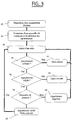
- the figure 3 shows a flow chart of a more elaborate embodiment of the invention.
- the verification provided for in figure 2 at step 34 of the figure 2 is only implemented, for a given pair of objects, on the first attempt to send an order from one object to another.
- the pairings are carried out by storing in an object identifiers of all the objects with which it is paired.
- the command transmitter 16 stores identifiers of the command receivers 4 and 10
- the command receiver 10 stores the identifiers of the command transmitters 16, 18 and 20.
- a marker is provided for each stored identifier; the marker is binary and its function appears from the description which follows. In "normal" operation of the installation, the marker has a first value - the value zero in the example.
- step 42 objects with a common key and between which pairings are defined.
- step 42 an order transmitter disappears.
- a new common key is provided in step 44.
- the marker associated with each identifier changes value; it is changed to the value 1. This value denotes that the pairing in question is temporarily invalidated.
- step 46 an object sends an order to another object.
- step 48 in the object to which the order is addressed, the existence of a pairing is checked. If the pairing exists, we go to step 50 and otherwise to step 52.
- step 52 in the recipient object, the order is refused if the pairing does not exist. This is a normal application of the rules of operation of objects.
- step 50 it is tested in the object having received the pairing whether the corresponding marker is valid - at state "0" in the example. If this is the case, we go to step 56 and otherwise to step 54.
- step 56 the order is executed.
- step 54 it is tested whether the new key is present in the sender object and in the recipient object of the order. If this is the case, we go to step 62 and otherwise to step 60.
- step 60 the pairing is deleted in the two objects.
- the pairing is therefore definitively invalidated; in the simplest mode of implementation, the memories of each of the objects of the pair storing the identifier of the other object of the pair are erased. This ensures that the excluded object can no longer be used in the installation. More complex solutions can be provided, for example warning the user by a particular signal or causing the objects to be completely inactivated. It is also possible to remove the pairing only after a second attempt, which leaves the user the possibility of transmitting the new common key to the object which does not have one.
- step 62 the order is executed and the identifier of the identifier of the other object is changed to the value "0" in the two objects.
- the pairing is again "validated” or "restored”.
- step 46 After steps 52, 56, 60 and 62, we go back to step 46.
- step 54 the two objects have the common key and we go to step 62: the markers of the identifier of the object 10 in the object 18 and of the identifier of the object 18 in the object 10 go to "0". If object 18 sends a new order to object 10, the flowchart is run through following steps 48, 50, 56. The presence of the marker makes it possible to test only once the presence of the new common key, this which simplifies exchanges.
- step 54 object 16 does not present not the new common key. Therefore, in step 60, the pairing is deleted.
- the identifiers of objects 4 and 10 are deleted in object 16 and the identifier of object 16 is deleted in objects 4 and 10. This prevents a subsequent attempt to use object 16 from being attempted. is successful - it would lead to going through the flowchart according to steps 48 and 52. This also makes it possible to free a memory location in the objects to allow other pairings.
- provision can be made for the verification to be carried out only during a predetermined period of time following the provision of a new common key; this mode of implementation ensures greater security, by eliminating objects which are not or rarely used. In this case, at the end of the predetermined period of time, the identifiers of the objects for which the marker is still at "1" are eliminated.
- Steps 48 to 62 are implemented for the various pairings considered; they can be implemented successively, at each occurrence of use of an object. They can also be implemented almost simultaneously: this could be the case if an object sends an order simultaneously to a plurality of other objects.
- the object 20 when the object 20 is used for the first time after providing a new common key, it issues a command to the objects 4, 8 and 12; thus, steps 48, 50, 54 and 62 are performed three times on each pair of objects.
- each pairing is carried out by storing in an object identifiers of all the objects with which it is paired.
- the pairing can be more simply carried out by partial storage: for example that of the identifier of an order transmitter in an order receiver, without the identifier of the order receiver is stored in the order transmitter, or by the storage in an order transmitter of one of the identifiers or addresses of the order receiver, without said order receiver containing the 'identifier of the order transmitter. It remains that in each case, the order receiver has the possibility of invalidating the pairing, or even of deleting it, as explained previously.
- the supply of the new common key is carried out using only one of the remote control points, nomadic or fixed.
- a particular keyboard command, or combination of keys allows this remote control to enter a mode where it generates a new key NK, for example using a pseudo-random algorithm, or even by any other means, that being without affecting the content of the invention.
- the old common OK key can be kept in memory by the remote control, for the reasons explained below. This variant has the advantage of simplicity and ease of implementation.
- At least two control points are necessary to allow the change of the common key of one of them.
- the keyboard procedure of the first variant is initiated, but this has the effect of causing the transmission by T1 of a particular authentication request.
- T1 sends a sign proving that it contains the old common key - it can be in the clear the value of this common key, or any other encrypted value derived from this common key.
- another remote control T2 On receipt of such an authentication request AND in response to at least one keyboard command from the user, another remote control T2 will send an acquisition signal to T1 provided that T2 has verified that the old common key transmitted by T1 was indeed that known to T2. It is only on receipt of such an acquisition signal that the remote control T1 is able to modify its own common key by creating NK while keeping the old value OK in memory. To increase the security corresponding to this method, it is possible to impose that the acquisition signal be transmitted in a short time range following the transmission of the particular authentication request signal.
- one of the objects - a remote control in the example - has the new key.
- the new NK key should then be distributed to the other control points.
- this diffusion takes place in a substantially collective manner, i. e. point to multipoint; according to a second variant, this broadcasting takes place by succession of point-to-point broadcasts.
- the object which contains the new key addresses, in response to a particular keyboard command from the user, or directly after the generation of the new key, a key change request message to all of the users. objects; the message simultaneously contains the old OK key and the new NK. Any object receiving this message, possibly repeated over a period of a few minutes, proceeds to modify its own current common key into a new key NK, after having verified the identity of its current key with the old key OK.
- Another form of this first so-called collective variant consists in the object having the new key simply sending a key change order accompanied by the new key NK.
- Each object receiving the general key change request order then initiating an authentication dialogue with the object having the new key, and accepting the new key NK only if this dialogue proves that the object having the new key contains the old common key OK. This prevents, as in the previous form, that an object of one installation does not react to a key change command coming from an object of another installation.
- the new key is transmitted from object to object, with at least one user operation during each transmission.
- the transmission of the new common key is accompanied by the transmission of the old common key, or else leads to a dialogue proving to the object receiving the new key that the object which transmits the new common key also possessed the old one. .
- the fact of providing a user operation during each transmission secures the provision of the new key.
- this last variant accommodates a low consumption mode of the points of command, which only gives them reception operation during manual activation. It is also possible in this second variant to impose the use of two objects to generate the new key.
- control points can be implemented for all the objects; however, it is advantageous to use them only to broadcast the new key to directional objects used as control points. Indeed, the control points are easily accessible by the user, which makes the second variant easy to implement. On the other hand, it can be complicated for the user to access each operator or receiver for manual control. We could also only implement these variants for nomadic remote controls, i.e. for control points which are not fixed: we can indeed assume that fixed control points cannot normally disappear.
- the new key can then be broadcast to the other objects as explained now.
- the distribution of the new key to the actuators is first possible according to the methods indicated in the patent application. 02 01 631 from 11.02.02.
- a message containing a group identifier is then sent - for example by one of the objects having undergone the initiating event.
- An object having undergone the initiating event and receiving this message stores the group identifier, and then considers that it is part of the group defined by this identifier.
- the instant of application of the initiating event can be used in each time reference object to secure the definition of the group.
- the initiating event can consist of a particular collective order of the remote control already having the new key; the initiating event can also be constituted by a specific action on a supply line common to the actuators, followed if necessary by the reception of a new key.
- actuators or fixed control points are identified as such - for example at installation or in the factory - it remains safe to send the new key, if necessary together with the old key, to the actuators and / or control points: indeed, such an order can only be accepted by objects identified as fixed and would not be accepted by a lost mobile control point.
- This solution also applies to the replacement of a fixed object: it would suffice that the fixed object to be replaced does not suffer the initiating event. In the case of a fixed control point, you can simply remove the battery power supply; for an actuator or a control point connected to the network, the control point can be disconnected.
- An object operating program therefore comprises routines adapted to the implementation of each step of the method.
- the method described above has the following advantages: in the event of loss or theft of an object - a remote control for example - it is unnecessary to carry out a complete re-pairing procedure to re-establish all the pairings between valid remote controls and actuators : these individual pairings are simply suspended by the common key change procedure and become valid again upon simple acknowledgment of agreement with the new common key; for the user, it is only necessary to trigger the supply of a new key, the other steps being undetectable and not requiring user intervention.
- the method keeps the pairings.
- the number of actions is therefore only a function of the number of control points and not of the number of pairings.
- the remote control 16 disappears, it suffices to validate the transmission of the new key to the remote controls 18 and 20, without having to re-establish the pairings (12, 18), (4, 20), ( 8, 20) and (12, 20).
- Another advantage is that the common key can be provided globally to all transmitters in an installation, regardless of pairings.
- the invention is not limited to the embodiments given above.
- the radio transmission used between a transmitter and a receiver is given only as an example and can be modified.
- the invention applies in particular whether the transmitters and receivers use a single frequency or each transmit on a different frequency, or by frequency hopping, or with different modulations. It would also be possible to use separate transmission media in the transmitter-to-receiver direction or in the receiver-to-transmitter direction, or else separate transmission media for groups of different transmitters or transmitters.
- the method applies as soon as the command transmitters or receivers are “bidirectional objects” capable of transmitting and receiving.
- command receivers and “operators” have been used, which apply in particular to the example of roller shutter operators.
- the receiver and the operator can be separate elements, as in the examples, or else form a single whole - for example by integrating the command receiver into the operator.
Landscapes
- Physics & Mathematics (AREA)
- General Physics & Mathematics (AREA)
- Engineering & Computer Science (AREA)
- Automation & Control Theory (AREA)
- Lock And Its Accessories (AREA)
- Selective Calling Equipment (AREA)
- Stored Programmes (AREA)
- Storage Device Security (AREA)
- Management, Administration, Business Operations System, And Electronic Commerce (AREA)
Claims (15)
- Verfahren zum Umprogrammieren eines Satzes von bidirektionalen Objekten (4, 10, 14, 16, 18, 20) einer Anlage, insbesondere einer Hausautomatisierungsanlage, wobei die Objekte der Anlage drahtlose Sende- und Empfangsmöglichkeiten haben und einen gemeinsamen Schlüssel enthalten, mindestens zwei Objekte der Anlage gepaart werden, um das Senden eines Befehls von einem Objekt (16, 18, 20) des Paares an das andere Objekt des Paares (4, 10, 14) und die Ausführung des Befehls durch das andere Objekt (4, 10, 14) zu ermöglichen, wobei das Verfahren zum Umprogrammieren die folgenden Schritte umfasst:• Bereitstellen (30) eines neuen gemeinsamen Schlüssels für die Objekte der Anlage mit Ausnahme eines auszuschließenden Objekts, wobei der Bereitstellungsschritt das Erzeugen des neuen gemeinsamen Schlüssels und das Verbreiten des erzeugten neuen gemeinsamen Schlüssels umfasst, wobei der Verbreitungsschritt beim Verbreiten des neuen gemeinsamen Schlüssels von einem Objekt zu einem anderen Objekt das Überprüfen umfasst, dass beide Objekte den alten gemeinsamen Schlüssel enthalten; dann• beim Senden (32) eines Befehls von einem Objekt an ein anderes damit gepaartes Objekt, Überprüfen (34), dass beide Objekte den neuen gemeinsamen Schlüssel enthalten, und• Verweigern (38) der Ausführung des Befehls durch das andere Objekt, wenn die beiden Objekte nicht den neuen gemeinsamen Schlüssel enthalten, wobei das Verfahren gekennzeichnet ist durch:• beispielsweise das Bereitstellen (30) eines neuen gemeinsamen Schlüssels für die Objekte der Anlage, mit Ausnahme des auszuschließenden Objekts, die Verbreitung eines verschlüsselten Wertes, der aus dem alten gemeinsamen Schlüssel abgeleitet ist, von einem Objekt des Paares auf das andere Objekt des Paares umfasst.
- Verfahren nach Anspruch 1, dadurch gekennzeichnet, dass der Überprüfungsschritt (34) für zwei gegebene Objekte nur bei dem ersten Befehl nach dem Bereitstellen des neuen gemeinsamen Schlüssels ausgeführt wird.
- Verfahren nach Anspruch 1 oder 2, dadurch gekennzeichnet, dass der Erzeugungsschritt von einem einzigen Objekt aus durchgeführt wird.
- Verfahren nach Anspruch 1 oder 2, dadurch gekennzeichnet, dass der Erzeugungsschritt von zwei Objekten aus durchgeführt wird.
- Verfahren nach einem der Ansprüche 1 bis 4, dadurch gekennzeichnet, dass der Verbreitungsschritt eine Punkt-zu-Mehrpunkt-Verbreitung umfasst.
- Verfahren nach einem der Ansprüche 1 bis 5, dadurch gekennzeichnet, dass der Verbreitungsschritt eine Punkt-zu-Punkt-Verbreitung umfasst.
- Verfahren nach Anspruch 6, dadurch gekennzeichnet, dass die Punkt-zu-Punkt-Verbreitung eine Benutzeraktion an jedem Punkt umfasst.
- Verfahren nach einem der Ansprüche 1 bis 4, dadurch gekennzeichnet, dass der Verbreitungsschritt Folgendes umfasst:• eine Punkt-zu-Punkt-Verbreitung aus einer Teilmenge der Objekte;• eine Punkt-zu-Mehrpunkt-Verbreitung zu einer anderen Teilmenge der Objekte.
- Programm zum Betreiben eines bidirektionalen Objekts (4, 10, 14), das von dem bidirektionalen Objekt (4, 10, 14) ausgeführt wird, als Befehlsempfänger fungiert und drahtlose Sende- und Empfangsmöglichkeiten aufweist, das zum Speichern mindestens eines gemeinsamen Schlüssels und mindestens einer Paarungsinformation geeignet ist, mit:a) einer Vorgehensweise zur Erzeugung eines neuen gemeinsamen Schlüssels;b) einer Vorgehensweise zur Übertragung eines neuen gemeinsamen Schlüssels an ein anderes Objekt, einschließlich der Überprüfung, ob beide Objekte den alten gemeinsamen Schlüssel enthalten;c) einer Vorgehensweise zum Empfang eines neuen gemeinsamen Schlüssels;c) einer Vorgehensweise zum Empfang eines Befehls;d) einer Vorgehensweise zum Überprüfen eines Befehls, der von einem gepaarten Senderobjekt empfangen wurde, auf das Vorkommen des gemeinsamen Schlüssels im Senderobjekt, unde) einer Vorgehensweise zur Verweigerung der Ausführung des Befehls, wenn die Überprüfung negativ ausfällt,wobei das Programm dadurch gekennzeichnet ist, dass die Überprüfung, dass die beiden Objekte den alten gemeinsamen Schlüssel enthalten, die Verbreitung eines verschlüsselten Wertes umfasst, der von dem alten gemeinsamen Schlüssel abgeleitet ist.
- Programm nach Anspruch 9, dadurch gekennzeichnet, dass die Vorgehensweise zum Überprüfen einer bestimmten Paarung nur bei dem ersten erhaltenen Befehl durchgeführt wird.
- Programm zum Betreiben eines bidirektionalen Objekts (16, 18, 20), das von dem bidirektionalen Objekt (16, 18, 20) ausgeführt wird, als Befehlssender fungiert und drahtlose Sende- und Empfangsfähigkeiten aufweist, und das dazu geeignet ist, mindestens einen gemeinsamen Schlüssel und mindestens eine Paarungsinformation zu speichern, mit:a) einer Vorgehensweise zur Erzeugung eines neuen gemeinsamen Schlüssels;b) einer Vorgehensweise zur Übertragung eines neuen gemeinsamen Schlüssels an ein anderes Objekt, einschließlich der Überprüfung, ob beide Objekte den alten gemeinsamen Schlüssel enthalten;c) einer Vorgehensweise zum Empfang eines neuen gemeinsamen Schlüssels;d) einer Vorgehensweise zum Senden eines Befehls an ein gepaartes Zielobjekt;e) einer Vorgehensweise zum Überprüfen des Vorkommens des gemeinsamen Schlüssels im Zielobjekt,wobei das Programm dadurch gekennzeichnet ist, dass die Überprüfung, dass die beiden Objekte den alten gemeinsamen Schlüssel enthalten, die Verbreitung eines verschlüsselten Wertes umfasst, der vom alten gemeinsamen Schlüssel abgeleitet ist.
- Programm nach Anspruch 12, dadurch gekennzeichnet, dass die Vorgehensweise zum Überprüfen einer bestimmten Paarung nur bei dem ersten gesendeten Befehl ausgeführt wird.
- Programm nach einem der Ansprüche 9 bis 12, dadurch gekennzeichnet, dass die Vorgehensweise des Erzeugens eine untergeordnete Vorgehensweise zum Senden eines Befehls für das Erzeugen des gemeinsamen Schlüssels an ein anderes Objekt umfasst.
- Programm nach einem der Ansprüche 9 bis 13, dadurch gekennzeichnet, dass es ferner eine Vorgehensweise zur Übertragung eines neuen gemeinsamen Schlüssels an mehrere andere Objekte umfasst.
- Bidirektionales Objekt, das Folgendes aufweist:• eine Stufe des drahtlosen Empfangs;• eine Stufe des drahtlosen Sendens;• eine logische Einheit, die die Empfangsstufe und die Sendestufe steuert, und• ein Speicher, der ein Programm nach einem der Ansprüche 9 bis 14 enthält.
Applications Claiming Priority (3)
| Application Number | Priority Date | Filing Date | Title |
|---|---|---|---|
| FR0203752A FR2837939B1 (fr) | 2002-03-26 | 2002-03-26 | Procede de reprogrammation d'objets bidirectionnels |
| FR0203752 | 2002-03-26 | ||
| PCT/FR2003/000860 WO2003081352A2 (fr) | 2002-03-26 | 2003-03-18 | Procede de reprogrammation d'objets bidirectionnels |
Publications (2)
| Publication Number | Publication Date |
|---|---|
| EP1490839A2 EP1490839A2 (de) | 2004-12-29 |
| EP1490839B1 true EP1490839B1 (de) | 2020-12-16 |
Family
ID=27839192
Family Applications (1)
| Application Number | Title | Priority Date | Filing Date |
|---|---|---|---|
| EP03725301.0A Expired - Lifetime EP1490839B1 (de) | 2002-03-26 | 2003-03-18 | Verfahren zur umprogrammierung bidirektionaler gegenständen |
Country Status (9)
| Country | Link |
|---|---|
| US (1) | US8552854B2 (de) |
| EP (1) | EP1490839B1 (de) |
| JP (1) | JP2005521307A (de) |
| KR (1) | KR20040102062A (de) |
| CN (1) | CN1643548B (de) |
| AU (1) | AU2003227846B2 (de) |
| ES (1) | ES2234456T1 (de) |
| FR (1) | FR2837939B1 (de) |
| WO (1) | WO2003081352A2 (de) |
Families Citing this family (10)
| Publication number | Priority date | Publication date | Assignee | Title |
|---|---|---|---|---|
| FR2869134B1 (fr) | 2004-04-16 | 2008-10-03 | Somfy Soc Par Actions Simplifiee | Procede de transmission d'informations entre objets bidirectionnels |
| ITMI20060409A1 (it) * | 2006-03-07 | 2007-09-08 | Nice Spa | Impianto tadioricevitore e radiotrasmettitore per automatismi radiocomandati di apeertura-chiusura |
| CN101309436B (zh) * | 2008-07-02 | 2012-04-18 | 三一重工股份有限公司 | 一种无线通信设备匹配认证方法、装置及系统 |
| FR2966625B1 (fr) | 2010-10-26 | 2012-12-21 | Somfy Sas | Procede de fonctionnement d'une installation domotique. |
| FR2966626B1 (fr) | 2010-10-26 | 2013-04-19 | Somfy Sas | Procede de fonctionnement d'une unite mobile de commande d'une installation domotique. |
| FR2966627B1 (fr) | 2010-10-26 | 2012-12-21 | Somfy Sas | Procede de fonctionnement d'une unite mobile de commande d'une installation domotique. |
| KR101243150B1 (ko) * | 2011-01-31 | 2013-03-13 | 국방과학연구소 | 표적 관리 시스템, 장치 및 방법 |
| FR2987531B1 (fr) * | 2012-02-27 | 2014-03-14 | Somfy Sas | Procede de configuration d'une installation domotique |
| US10360748B2 (en) * | 2017-08-14 | 2019-07-23 | Q & K International Group Limited | Method of achieving free-pairing wireless door lock based on DIP switch, a wireless door lock and a communication method for the wireless door lock |
| US10396860B2 (en) * | 2017-09-29 | 2019-08-27 | The Boeing Company | System and method for automated calibration of wireless identification device location determination equipment |
Family Cites Families (16)
| Publication number | Priority date | Publication date | Assignee | Title |
|---|---|---|---|---|
| US3821704A (en) | 1972-03-13 | 1974-06-28 | D Sabsay | Self re keying security device with coded key |
| US4529980A (en) * | 1982-09-23 | 1985-07-16 | Chamberlain Manufacturing Corporation | Transmitter and receiver for controlling the coding in a transmitter and receiver |
| USRE35364E (en) | 1985-10-29 | 1996-10-29 | The Chamberlain Group, Inc. | Coding system for multiple transmitters and a single receiver for a garage door opener |
| JPS6462044A (en) | 1987-09-02 | 1989-03-08 | Matsushita Electric Industrial Co Ltd | Digital radio communication equipment |
| US5148159A (en) * | 1989-04-26 | 1992-09-15 | Stanley Electronics | Remote control system with teach/learn setting of identification code |
| US5576701A (en) * | 1990-07-16 | 1996-11-19 | The Chamberlain Group, Inc. | Remote actuating apparatus comprising keypad controlled transmitter |
| US5144667A (en) * | 1990-12-20 | 1992-09-01 | Delco Electronics Corporation | Method of secure remote access |
| US6166650A (en) | 1991-05-29 | 2000-12-26 | Microchip Technology, Inc. | Secure self learning system |
| US5686904A (en) * | 1991-05-29 | 1997-11-11 | Microchip Technology Incorporated | Secure self learning system |
| EP0688929B1 (de) * | 1994-06-21 | 2004-10-13 | Microchip Technology Inc. | Geschütztes Selbstlernen |
| US6026165A (en) * | 1996-06-20 | 2000-02-15 | Pittway Corporation | Secure communications in a wireless system |
| IE20000728A1 (en) | 1999-09-13 | 2001-04-04 | Phisilog Res Ltd | "A remote control transmitter" |
| US6617961B1 (en) * | 1999-11-15 | 2003-09-09 | Strattec Security Corporation | Security system for a vehicle and method of operating same |
| EP1104213A3 (de) | 1999-11-29 | 2003-05-21 | Philips Intellectual Property & Standards GmbH | Drahtloses Netzwerk mit einer Prozedur zur Schlüsseländerung |
| CA2391405C (en) | 2000-04-10 | 2006-01-10 | Zensys A/S | Rf home automation system comprising replicable controllers |
| EP1410600B1 (de) * | 2001-07-16 | 2008-08-27 | Research In Motion Limited | System und verfahren zur unterstützung von mehreren zertifizierungsbehörden auf einem mobilen kommunikationsgerät |
-
2002
- 2002-03-26 FR FR0203752A patent/FR2837939B1/fr not_active Expired - Lifetime
-
2003
- 2003-03-18 ES ES03725301T patent/ES2234456T1/es active Pending
- 2003-03-18 JP JP2003579019A patent/JP2005521307A/ja active Pending
- 2003-03-18 CN CN038071193A patent/CN1643548B/zh not_active Expired - Lifetime
- 2003-03-18 KR KR10-2004-7015496A patent/KR20040102062A/ko not_active Ceased
- 2003-03-18 EP EP03725301.0A patent/EP1490839B1/de not_active Expired - Lifetime
- 2003-03-18 US US10/506,951 patent/US8552854B2/en not_active Expired - Lifetime
- 2003-03-18 WO PCT/FR2003/000860 patent/WO2003081352A2/fr not_active Ceased
- 2003-03-18 AU AU2003227846A patent/AU2003227846B2/en not_active Ceased
Non-Patent Citations (1)
| Title |
|---|
| None * |
Also Published As
| Publication number | Publication date |
|---|---|
| CN1643548B (zh) | 2011-07-13 |
| US20050225428A1 (en) | 2005-10-13 |
| CN1643548A (zh) | 2005-07-20 |
| FR2837939A1 (fr) | 2003-10-03 |
| AU2003227846A1 (en) | 2003-10-08 |
| WO2003081352A3 (fr) | 2004-04-01 |
| FR2837939B1 (fr) | 2004-09-17 |
| WO2003081352A2 (fr) | 2003-10-02 |
| US8552854B2 (en) | 2013-10-08 |
| ES2234456T1 (es) | 2005-07-01 |
| JP2005521307A (ja) | 2005-07-14 |
| EP1490839A2 (de) | 2004-12-29 |
| KR20040102062A (ko) | 2004-12-03 |
| AU2003227846B2 (en) | 2008-06-19 |
Similar Documents
| Publication | Publication Date | Title |
|---|---|---|
| EP1476859B1 (de) | Verfahren zur zuordnung bidirektionaler gegenständen | |
| EP1587044B1 (de) | Verfahren zur Datenübertragung zwischen bidirektionalen Gegenständen | |
| EP1490839B1 (de) | Verfahren zur umprogrammierung bidirektionaler gegenständen | |
| EP2633506B1 (de) | Verfahren für den betrieb einer mobilen steuereinheit einer domotikanlage | |
| WO2003054827A1 (fr) | Procede d'appariement de transmetteurs et de recepteur | |
| EP1410360B1 (de) | Verfahren zur zuordnung von sender zu empfänger | |
| FR2912821A1 (fr) | Procede de configuration d'une installation domotique et outil pour la mise en oeuvre d'un tel procede | |
| WO2012055857A1 (fr) | Procede de fonctionnement d'une unite mobile de commande d'une installation domotique | |
| EP1476860B1 (de) | Verfahren zur Definition einer Gruppe zwischen bidirektionalen Objekten | |
| EP1561192B1 (de) | Verfahren zur sicherung des registrierungsmodus einer hausautomatisierungsvorrichtung | |
| FR2685525A1 (fr) | Commande a distance pour un moyen de man oeuvre, en particulier pour un vehicule automobile. | |
| EP2632084B1 (de) | Konfigurationsverfahren einer Heimanlage | |
| EP1527430A1 (de) | Verfahen zur karakterisierung eines bidirektionalen objektes | |
| EP1722340B1 (de) | Betriebsverfahren für eine Hausautomatisierungsanlage und zugehörige Hausautomatisierungsanlage | |
| EP0724056B1 (de) | Fernbedienungseinrichtung mit Hertzschen, infraroten Wellen od. dgl. zur Steuerung von motorbetriebenen Schliesssystemen | |
| FR2531587A1 (fr) | Procede pour la transmission d'informations sur un canal d'echanges unique et application de ce procede notamment a des dispositifs formant un systeme d'alarme | |
| FR2859854A1 (fr) | Procede de communication entre objets | |
| FR2834578A1 (fr) | Procede d'authentifications successives d'une unite par une autre | |
| FR2782112A1 (fr) | Procede et dispositif de commande d'acces a un lieu collectif | |
| WO2007026069A1 (fr) | Procede et dispositif d 'activation et de controle a distance de multiples appareillages electriques par telecommande |
Legal Events
| Date | Code | Title | Description |
|---|---|---|---|
| PUAI | Public reference made under article 153(3) epc to a published international application that has entered the european phase |
Free format text: ORIGINAL CODE: 0009012 |
|
| 17P | Request for examination filed |
Effective date: 20041026 |
|
| AK | Designated contracting states |
Kind code of ref document: A2 Designated state(s): AT BE BG CH CY CZ DE DK EE ES FI FR GB GR HU IE IT LI LU MC NL PT RO SE SI SK TR |
|
| AX | Request for extension of the european patent |
Extension state: AL LT LV MK |
|
| 17Q | First examination report despatched |
Effective date: 20081111 |
|
| STAA | Information on the status of an ep patent application or granted ep patent |
Free format text: STATUS: EXAMINATION IS IN PROGRESS |
|
| GRAP | Despatch of communication of intention to grant a patent |
Free format text: ORIGINAL CODE: EPIDOSNIGR1 |
|
| STAA | Information on the status of an ep patent application or granted ep patent |
Free format text: STATUS: GRANT OF PATENT IS INTENDED |
|
| RIC1 | Information provided on ipc code assigned before grant |
Ipc: G07C 9/00 20200101AFI20200723BHEP Ipc: G08C 19/28 20060101ALN20200723BHEP |
|
| INTG | Intention to grant announced |
Effective date: 20200813 |
|
| RIN1 | Information on inventor provided before grant (corrected) |
Inventor name: AUTRET, CAPUCINE Inventor name: ORSAT, JEAN-MICHEL |
|
| RAP1 | Party data changed (applicant data changed or rights of an application transferred) |
Owner name: SOMFY ACTIVITES SA |
|
| GRAS | Grant fee paid |
Free format text: ORIGINAL CODE: EPIDOSNIGR3 |
|
| GRAA | (expected) grant |
Free format text: ORIGINAL CODE: 0009210 |
|
| STAA | Information on the status of an ep patent application or granted ep patent |
Free format text: STATUS: THE PATENT HAS BEEN GRANTED |
|
| AK | Designated contracting states |
Kind code of ref document: B1 Designated state(s): AT BE BG CH CY CZ DE DK EE ES FI FR GB GR HU IE IT LI LU MC NL PT RO SE SI SK TR |
|
| REG | Reference to a national code |
Ref country code: GB Ref legal event code: FG4D Free format text: NOT ENGLISH |
|
| REG | Reference to a national code |
Ref country code: DE Ref legal event code: R096 Ref document number: 60352604 Country of ref document: DE |
|
| REG | Reference to a national code |
Ref country code: IE Ref legal event code: FG4D Free format text: LANGUAGE OF EP DOCUMENT: FRENCH |
|
| REG | Reference to a national code |
Ref country code: AT Ref legal event code: REF Ref document number: 1346278 Country of ref document: AT Kind code of ref document: T Effective date: 20210115 |
|
| PG25 | Lapsed in a contracting state [announced via postgrant information from national office to epo] |
Ref country code: GR Free format text: LAPSE BECAUSE OF FAILURE TO SUBMIT A TRANSLATION OF THE DESCRIPTION OR TO PAY THE FEE WITHIN THE PRESCRIBED TIME-LIMIT Effective date: 20210317 Ref country code: FI Free format text: LAPSE BECAUSE OF FAILURE TO SUBMIT A TRANSLATION OF THE DESCRIPTION OR TO PAY THE FEE WITHIN THE PRESCRIBED TIME-LIMIT Effective date: 20201216 |
|
| REG | Reference to a national code |
Ref country code: AT Ref legal event code: MK05 Ref document number: 1346278 Country of ref document: AT Kind code of ref document: T Effective date: 20201216 |
|
| REG | Reference to a national code |
Ref country code: NL Ref legal event code: MP Effective date: 20201216 |
|
| PG25 | Lapsed in a contracting state [announced via postgrant information from national office to epo] |
Ref country code: BG Free format text: LAPSE BECAUSE OF FAILURE TO SUBMIT A TRANSLATION OF THE DESCRIPTION OR TO PAY THE FEE WITHIN THE PRESCRIBED TIME-LIMIT Effective date: 20210316 Ref country code: SE Free format text: LAPSE BECAUSE OF FAILURE TO SUBMIT A TRANSLATION OF THE DESCRIPTION OR TO PAY THE FEE WITHIN THE PRESCRIBED TIME-LIMIT Effective date: 20201216 |
|
| PG25 | Lapsed in a contracting state [announced via postgrant information from national office to epo] |
Ref country code: NL Free format text: LAPSE BECAUSE OF FAILURE TO SUBMIT A TRANSLATION OF THE DESCRIPTION OR TO PAY THE FEE WITHIN THE PRESCRIBED TIME-LIMIT Effective date: 20201216 |
|
| PG25 | Lapsed in a contracting state [announced via postgrant information from national office to epo] |
Ref country code: EE Free format text: LAPSE BECAUSE OF FAILURE TO SUBMIT A TRANSLATION OF THE DESCRIPTION OR TO PAY THE FEE WITHIN THE PRESCRIBED TIME-LIMIT Effective date: 20201216 Ref country code: CZ Free format text: LAPSE BECAUSE OF FAILURE TO SUBMIT A TRANSLATION OF THE DESCRIPTION OR TO PAY THE FEE WITHIN THE PRESCRIBED TIME-LIMIT Effective date: 20201216 Ref country code: SK Free format text: LAPSE BECAUSE OF FAILURE TO SUBMIT A TRANSLATION OF THE DESCRIPTION OR TO PAY THE FEE WITHIN THE PRESCRIBED TIME-LIMIT Effective date: 20201216 Ref country code: PT Free format text: LAPSE BECAUSE OF FAILURE TO SUBMIT A TRANSLATION OF THE DESCRIPTION OR TO PAY THE FEE WITHIN THE PRESCRIBED TIME-LIMIT Effective date: 20210416 Ref country code: RO Free format text: LAPSE BECAUSE OF FAILURE TO SUBMIT A TRANSLATION OF THE DESCRIPTION OR TO PAY THE FEE WITHIN THE PRESCRIBED TIME-LIMIT Effective date: 20201216 |
|
| PG25 | Lapsed in a contracting state [announced via postgrant information from national office to epo] |
Ref country code: AT Free format text: LAPSE BECAUSE OF FAILURE TO SUBMIT A TRANSLATION OF THE DESCRIPTION OR TO PAY THE FEE WITHIN THE PRESCRIBED TIME-LIMIT Effective date: 20201216 |
|
| REG | Reference to a national code |
Ref country code: DE Ref legal event code: R097 Ref document number: 60352604 Country of ref document: DE |
|
| PLBE | No opposition filed within time limit |
Free format text: ORIGINAL CODE: 0009261 |
|
| STAA | Information on the status of an ep patent application or granted ep patent |
Free format text: STATUS: NO OPPOSITION FILED WITHIN TIME LIMIT |
|
| PG25 | Lapsed in a contracting state [announced via postgrant information from national office to epo] |
Ref country code: MC Free format text: LAPSE BECAUSE OF FAILURE TO SUBMIT A TRANSLATION OF THE DESCRIPTION OR TO PAY THE FEE WITHIN THE PRESCRIBED TIME-LIMIT Effective date: 20201216 Ref country code: IT Free format text: LAPSE BECAUSE OF FAILURE TO SUBMIT A TRANSLATION OF THE DESCRIPTION OR TO PAY THE FEE WITHIN THE PRESCRIBED TIME-LIMIT Effective date: 20201216 |
|
| REG | Reference to a national code |
Ref country code: CH Ref legal event code: PL |
|
| 26N | No opposition filed |
Effective date: 20210917 |
|
| GBPC | Gb: european patent ceased through non-payment of renewal fee |
Effective date: 20210318 |
|
| PG25 | Lapsed in a contracting state [announced via postgrant information from national office to epo] |
Ref country code: ES Free format text: LAPSE BECAUSE OF FAILURE TO SUBMIT A TRANSLATION OF THE DESCRIPTION OR TO PAY THE FEE WITHIN THE PRESCRIBED TIME-LIMIT Effective date: 20201216 Ref country code: DK Free format text: LAPSE BECAUSE OF FAILURE TO SUBMIT A TRANSLATION OF THE DESCRIPTION OR TO PAY THE FEE WITHIN THE PRESCRIBED TIME-LIMIT Effective date: 20201216 |
|
| REG | Reference to a national code |
Ref country code: BE Ref legal event code: MM Effective date: 20210331 |
|
| PG25 | Lapsed in a contracting state [announced via postgrant information from national office to epo] |
Ref country code: LI Free format text: LAPSE BECAUSE OF NON-PAYMENT OF DUE FEES Effective date: 20210331 Ref country code: LU Free format text: LAPSE BECAUSE OF NON-PAYMENT OF DUE FEES Effective date: 20210318 Ref country code: CH Free format text: LAPSE BECAUSE OF NON-PAYMENT OF DUE FEES Effective date: 20210331 Ref country code: GB Free format text: LAPSE BECAUSE OF NON-PAYMENT OF DUE FEES Effective date: 20210318 Ref country code: IE Free format text: LAPSE BECAUSE OF NON-PAYMENT OF DUE FEES Effective date: 20210318 |
|
| PG25 | Lapsed in a contracting state [announced via postgrant information from national office to epo] |
Ref country code: SI Free format text: LAPSE BECAUSE OF FAILURE TO SUBMIT A TRANSLATION OF THE DESCRIPTION OR TO PAY THE FEE WITHIN THE PRESCRIBED TIME-LIMIT Effective date: 20201216 |
|
| PGFP | Annual fee paid to national office [announced via postgrant information from national office to epo] |
Ref country code: DE Payment date: 20220216 Year of fee payment: 20 |
|
| PGFP | Annual fee paid to national office [announced via postgrant information from national office to epo] |
Ref country code: FR Payment date: 20220318 Year of fee payment: 20 |
|
| PG25 | Lapsed in a contracting state [announced via postgrant information from national office to epo] |
Ref country code: BE Free format text: LAPSE BECAUSE OF NON-PAYMENT OF DUE FEES Effective date: 20210331 |
|
| REG | Reference to a national code |
Ref country code: DE Ref legal event code: R071 Ref document number: 60352604 Country of ref document: DE |
|
| PG25 | Lapsed in a contracting state [announced via postgrant information from national office to epo] |
Ref country code: HU Free format text: LAPSE BECAUSE OF FAILURE TO SUBMIT A TRANSLATION OF THE DESCRIPTION OR TO PAY THE FEE WITHIN THE PRESCRIBED TIME-LIMIT; INVALID AB INITIO Effective date: 20030318 |
|
| PG25 | Lapsed in a contracting state [announced via postgrant information from national office to epo] |
Ref country code: CY Free format text: LAPSE BECAUSE OF FAILURE TO SUBMIT A TRANSLATION OF THE DESCRIPTION OR TO PAY THE FEE WITHIN THE PRESCRIBED TIME-LIMIT Effective date: 20201216 |
|
| PG25 | Lapsed in a contracting state [announced via postgrant information from national office to epo] |
Ref country code: TR Free format text: LAPSE BECAUSE OF FAILURE TO SUBMIT A TRANSLATION OF THE DESCRIPTION OR TO PAY THE FEE WITHIN THE PRESCRIBED TIME-LIMIT Effective date: 20201216 |