EP1490873B1 - Positionserfassung von bandführungsstift in einem kassettengehäuse - Google Patents
Positionserfassung von bandführungsstift in einem kassettengehäuse Download PDFInfo
- Publication number
- EP1490873B1 EP1490873B1 EP03745202A EP03745202A EP1490873B1 EP 1490873 B1 EP1490873 B1 EP 1490873B1 EP 03745202 A EP03745202 A EP 03745202A EP 03745202 A EP03745202 A EP 03745202A EP 1490873 B1 EP1490873 B1 EP 1490873B1
- Authority
- EP
- European Patent Office
- Prior art keywords
- pin
- cartridge shell
- sensing
- cartridge
- arrangement
- Prior art date
- Legal status (The legal status is an assumption and is not a legal conclusion. Google has not performed a legal analysis and makes no representation as to the accuracy of the status listed.)
- Expired - Lifetime
Links
- 238000001514 detection method Methods 0.000 claims abstract description 12
- 238000000034 method Methods 0.000 claims abstract description 11
- 238000000605 extraction Methods 0.000 claims 2
- 238000012544 monitoring process Methods 0.000 description 6
- 239000000463 material Substances 0.000 description 5
- 230000007246 mechanism Effects 0.000 description 5
- 238000005516 engineering process Methods 0.000 description 4
- XEEYBQQBJWHFJM-UHFFFAOYSA-N Iron Chemical compound [Fe] XEEYBQQBJWHFJM-UHFFFAOYSA-N 0.000 description 2
- 230000000694 effects Effects 0.000 description 2
- 238000011084 recovery Methods 0.000 description 2
- 229910001220 stainless steel Inorganic materials 0.000 description 2
- 239000010935 stainless steel Substances 0.000 description 2
- CWYNVVGOOAEACU-UHFFFAOYSA-N Fe2+ Chemical compound [Fe+2] CWYNVVGOOAEACU-UHFFFAOYSA-N 0.000 description 1
- 229910000831 Steel Inorganic materials 0.000 description 1
- 238000004891 communication Methods 0.000 description 1
- 239000000470 constituent Substances 0.000 description 1
- 238000010276 construction Methods 0.000 description 1
- 238000013500 data storage Methods 0.000 description 1
- 238000013461 design Methods 0.000 description 1
- 229910052742 iron Inorganic materials 0.000 description 1
- 238000005259 measurement Methods 0.000 description 1
- 239000007769 metal material Substances 0.000 description 1
- 230000003287 optical effect Effects 0.000 description 1
- 230000000246 remedial effect Effects 0.000 description 1
- 230000035945 sensitivity Effects 0.000 description 1
- 239000010959 steel Substances 0.000 description 1
Images

Classifications
-
- G—PHYSICS
- G11—INFORMATION STORAGE
- G11B—INFORMATION STORAGE BASED ON RELATIVE MOVEMENT BETWEEN RECORD CARRIER AND TRANSDUCER
- G11B23/00—Record carriers not specific to the method of recording or reproducing; Accessories, e.g. containers, specially adapted for co-operation with the recording or reproducing apparatus ; Intermediate mediums; Apparatus or processes specially adapted for their manufacture
- G11B23/20—Record carriers not specific to the method of recording or reproducing; Accessories, e.g. containers, specially adapted for co-operation with the recording or reproducing apparatus ; Intermediate mediums; Apparatus or processes specially adapted for their manufacture with provision for splicing to provide permanent or temporary connections
- G11B23/26—Record carriers not specific to the method of recording or reproducing; Accessories, e.g. containers, specially adapted for co-operation with the recording or reproducing apparatus ; Intermediate mediums; Apparatus or processes specially adapted for their manufacture with provision for splicing to provide permanent or temporary connections of leaders for loading or threading, e.g. to form a temporary connection
-
- G—PHYSICS
- G11—INFORMATION STORAGE
- G11B—INFORMATION STORAGE BASED ON RELATIVE MOVEMENT BETWEEN RECORD CARRIER AND TRANSDUCER
- G11B15/00—Driving, starting or stopping record carriers of filamentary or web form; Driving both such record carriers and heads; Guiding such record carriers or containers therefor; Control thereof; Control of operating function
- G11B15/02—Control of operating function, e.g. switching from recording to reproducing
- G11B15/16—Control of operating function, e.g. switching from recording to reproducing by sensing presence, absence or position of record carrier or container
-
- G—PHYSICS
- G11—INFORMATION STORAGE
- G11B—INFORMATION STORAGE BASED ON RELATIVE MOVEMENT BETWEEN RECORD CARRIER AND TRANSDUCER
- G11B15/00—Driving, starting or stopping record carriers of filamentary or web form; Driving both such record carriers and heads; Guiding such record carriers or containers therefor; Control thereof; Control of operating function
- G11B15/60—Guiding record carrier
- G11B15/66—Threading; Loading; Automatic self-loading
-
- G—PHYSICS
- G11—INFORMATION STORAGE
- G11B—INFORMATION STORAGE BASED ON RELATIVE MOVEMENT BETWEEN RECORD CARRIER AND TRANSDUCER
- G11B15/00—Driving, starting or stopping record carriers of filamentary or web form; Driving both such record carriers and heads; Guiding such record carriers or containers therefor; Control thereof; Control of operating function
- G11B15/60—Guiding record carrier
- G11B15/66—Threading; Loading; Automatic self-loading
- G11B15/67—Threading; Loading; Automatic self-loading by extracting end of record carrier from container or spool
Definitions
- the present invention relates to an arrangement for sensing the position of a leader pin on a tape which is located within a cartridge shell.
- a drive for the cartridge magnetic tape may entail implements such as small levers on a picking mechanism adapted to physically move when the pin is positioned to extend into the picking mechanism.
- the prior art structure fails to provide any capability of being able to detect if the pin is in its proper location or orientation prior to attempting to pick the pin, and also exposes the mechanism to a potential hang-up or dislodging of the pin if out of place or dislocated within the tape cartridge.
- the design of the mechanism in the state-of-the art is also extremely small in size and, resultingly, fragile in nature due to the demands of the tight space within which it is designed to implement mechanical sensing in a tape cartridge, for instance, such as an LTO cartridge, and consequently is prone to reliability problems in the operation or functioning thereof.
- US 6 034 839 A discloses an arrangement for sensing the position and the motion of motive elements for loading a tape leader pin from a single reel cartridge to a take-up reel.
- U.S. Patent No. 4,589,608 discloses a cassette loading apparatus wherein various mechanical devices are adapted to provide for appropriate tape positioning in the loading of a magnetic tape cassette.
- Baur U.S. Patent No. 5,454,681 discloses an automatic archiving and retrieval system for computer data storage cassettes.
- JP 1222888A and JP 63053771A each disclose cartridge magazines and methods for detecting pin positioning by means of a robot.
- this type of structure does not concern itself with the positioning of a pin on a tape within a cartridge shell adapted to provide for the feed of a magnetic tape.
- JP62062252A wherein a pin position detector is provided for primarily detecting pins on an integrated circuit package.
- IBM Technical Disclosure Bulletin, Volume 23, No. 4 of September 1980, pages 1657 and 1658 relates to an arrangement for detecting a web or tape wrapped on a hub.
- the detection arrangement senses as to when more than one turn of a magnetic tape is wrapped around the hub of a take-up reel.
- the invention provides for the detection of pin location from the exterior of the cartridge in either electromagnetic or electrostatic modes without having to physically enter the interior of the cartridge shell.
- This sensing or detection of the pin can be readily achieved by monitoring the changes in the electrical properties of an electromagnetic circuit, or through the intermediary of electrostatic detection means.
- the correct position of the pin on the tape leader within the cartridge shell can be readily determined, pursuant to a first embodiment, by positioning an electromagnetic circuit in the drive at such a position whereby the pin alters the inductance of the electromagnetic circuit when it is located in the correct position in the cartridge upon the cartridge being properly located within the drive.
- the inductance will be reduced for pins which are made of a conductive ferrous material; for instance, iron/steel.
- Non-ferrous pins; or stainless steel pins do not cause the inductance to be reduced, but modified by the introduction of eddy currents into the pins.
- the sensing of the pin in the cartridge is achieved by locating the electromagnetic circuit at opposite external ends of the pin, and whereby alternative electromagnetic circuits can be employed depending upon the sensitivity and electromagnetic and conductive properties of the pin, in this instance, being possibly constituted of a stainless steel material as commonly employed in LTO cartridges.
- sensing is effected through electrostatic detection means.
- electromagnetic circuitry can be employed in order to detect both the top and bottom of the tape leader pin independently if each other, and which renders it able to derive the positioning or possible misalignment of the pin on the tape at opposite sides of the cartridge shell.
- multiple sensors can be arranged on each side of the cartridge, so as to facilitate monitoring the pin position during picking and placement of the pin in the cartridge.
- multiple pin sensing structure it is possible to detect the situation in which the pin has proper placement and is being extracted from the media cartridge in the proper orientation thereof.
- error recovery procedures can be implemented in an attempt to appropriately align the pin in the media cartridge, or to abort the loading thereof prior to removing the pin from the cartridge, subsequent to which it would be impossible to replace the pin if improperly oriented.
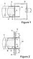
- FIG. 1 of the drawings there is diagrammatically illustrated an end portion 10 of a cartridge shell 12.
- a pin 14 is either rotatably journaled or non-rotatably supported therein, and is attached to a leading end 16 of a magnetic tape 18 as is well known in the art.
- the cartridge shell 12 may comprise a constituent of a magnetic tape cartridge, such as an LTO media cartridge.
- the positioning of an electromagnetic circuit 20 in communication with the opposite ends of the pin 14 externally of the cartridge shell 12 enables monitoring the changes in electrical properties of the electromagnetic circuit 20 in dependence upon the either appropriate or incorrect positioning of the tape pin 14.
- the correct placement of the pin 14 is readily determined by positioning the electromagnetic circuit 20 in the drive at a location such that the pin 14 alters the inductance V of the electromagnetic circuit when the former is in a correct orientation within the cartridge shell 12, with the media cartridge being properly located in the cassette drive.
- the electromagnetic circuitry 30 can be independently operated at opposite pin ends, or independent circuits 32, 34 provided at, respectively, the opposite ends 26, 28 of the pin 14. This enables monitoring the pin position during the picking and/or placing of the pin in the cartridge shell 12.
- This type of circuitry wherein the independent monitoring of the opposite ends of each of the pin 14 is effected, provides an improved versatility and degree of precision in measurement of the pin positioning or orientation.
- the pin-on-tape 14 may be detected through the use of multiple electromagnetic circuits 40,42;44,46 at respectively the opposite ends of the pin 14 on the opposite sides of the cartridge shell 12.
- circuits 40,42; 44, 46 upon movement of the pin detect that the pin 14 was not properly picked, an error recovery procedure can be implemented in an attempt to realign and reseat the pin 14 properly within the cartridge, or to abort the load of the media cartridge before the pin is removed from the cartridge, subsequent to which it would be impossible to correctly replace the pin 14 if improperly picked.
Landscapes
- Automatic Tape Cassette Changers (AREA)
- Registering, Tensioning, Guiding Webs, And Rollers Therefor (AREA)
- Impression-Transfer Materials And Handling Thereof (AREA)
- Mechanical Pencils And Projecting And Retracting Systems Therefor, And Multi-System Writing Instruments (AREA)
- Geophysics And Detection Of Objects (AREA)
- Automatic Disk Changers (AREA)
- Apparatus For Radiation Diagnosis (AREA)
- Air Bags (AREA)
Claims (10)
- Anordnung zum Erfassen der Position eines Stiftes (14) auf einem Band, das sich im Gehäuse einer Medienkassette (12) befindet; wobei die Anordnung Folgendes umfasst:einen Stift (14), der an einem Vorspannende (16) des Bandes befestigt ist, das sich in dem Kassettengehäuse (12) nahe einem offenen Ende (12a) des Kassettengehäuses befindet, wobei sich der Stift zwischen gegenüberliegenden Außenwänden des Kassettengehäuses erstreckt und Enden (26, 28) hat, die von den gegenüberliegenden Außenwänden gehalten werden; undeine Baugruppe zur Positionserfassung (20, 30, 32, 34, 40, 42, 44, 46), die sich außerhalb der gegenüberliegenden Wände des Kassettengehäuses in der Nähe der Enden des Stiftes befindet, wobei die Baugruppe zur Positionserfassung Mittel zum Erkennen der Lage des Stiftes umfasst.
- Anordnung nach Anspruch 1, wobei die Baugruppe zur Positionserfassung eine elektromagnetische Schaltung (20, 30) umfasst, die das Mittel zum gleichzeitigen Erkennen der gegenüberliegenden Enden des Stiftes bildet.
- Anordnung nach Anspruch 1, wobei die Baugruppe zur Positionserfassung mindestens zwei elektromagnetische Schaltungen (30, 32, 34) umfasst, die das Erkennungsmittel bilden, wobei jede dieser elektromagnetischen Schaltungen unabhängig voneinander ein gegenüberliegendes Ende des Stiftes erfasst, damit die Lage und Ausrichtung des Stiftes innerhalb des Kassettengehäuses gemeinsam ermittelt wird.
- Anordnung nach Anspruch 1, wobei die Baugruppe zur Positionserfassung ein Paar von im Abstand zueinander angeordneten elektromagnetischen Schaltungen (40, 42, 44, 46) an der jeweiligen äußeren Oberfläche der gegenüberliegenden Wände des Kassettengehäuses umfasst, damit die Position und Ausrichtung der gegenüberliegenden Enden des Stiftes unabhängig voneinander erkannt werden, wobei jedes der Paare elektromagnetischer Schaltungen in Bezug auf einander entlang der Wandoberfläche des Kassettengehäuses auf Abstand angeordnet ist, damit das Erkennen der korrekten Aufnahme des Stift und das Herausziehen des Stiftes in einer korrekten Ausrichtung erleichtert wird.
- Anordnung nach Anspruch 4, wobei der Zwischenraum zwischen den paarweisen elektromagnetischen Schaltungen an jeder gegenüberliegenden Oberfläche des Kassettengehäuses das Einrichten von Verfahrensweisen zur Fehlerkorrektur beim Positionieren des Stiftes bei den Bemühungen ermöglicht, den Stift in das Kassettengehäuse wieder einzusetzen oder seine Belastung vor dem Entfernen des Stiftes aus dem Kassettengehäuse zu vermeiden.
- Anordnung nach Anspruch 1, wobei das Mittel zum Erkennen des Stiftes eine Anordnung zur elektrostatischen Positionserfassung umfasst.
- Verfahren zur Positionserfassung eines Stiftes (14) auf einem Band, das sich im Gehäuse einer Medienkassette (12) befindet, wobei das Verfahren Folgendes umfasst:Bereitstellen eines Stiftes (14), der am Vorspannende (16) eines Bandes befestigt ist, das sich in dem Kassettengehäuse (12) nahe einem offenen Ende (12a) des Kassettengehäuses befindet, wobei sich der Stift zwischen gegenüberliegenden Außenwänden des Kassettengehäuses erstreckt und Enden (26, 28) hat, die in den gegenüberliegenden Außenwänden gelagert sind; undaußerhalb der gegenüberliegenden Wände des Kassettengehäuses in der Nähe der Enden des Stiftes eine Baugruppe zur Positionserfassung (20, 30, 32, 34, 40, 42, 44, 46), wobei diese Erfassungsbaugruppe Mittel zum Erkennen der Lage der Enden des Stiftes umfasst.
- Verfahren nach Anspruch 7, wobei die Baugruppe zur Positionserfassung eine elektromagnetische Schaltung (20, 30) umfasst, die das Mittel zum gleichzeitigen Erkennen der gegenüberliegenden Enden des Stiftes bildet.
- Verfahren nach Anspruch 7, wobei die Erfassungsbaugruppe mindestens zwei elektromagnetische Schaltungen (30, 32, 34) umfasst, die das Erkennungsmittel bilden, wobei die elektromagnetischen Schaltungen unabhängig voneinander ein gegenüberliegendes Ende des Stiftes erfassen, damit sie gemeinsam die Position und Ausrichtung des Stiftes innerhalb des Kassettengehäuses ermitteln.
- Verfahren nach Anspruch 7, wobei die Erfassungsbaugruppe ein Paar von mit Abstand zueinander angeordneten elektromagnetischen Schaltungen (40, 42, 44, 46) an der jeweiligen äußeren Oberfläche der gegenüberliegenden Wände des Kassettengehäuses umfasst, um unabhängig voneinander die Position und Ausrichtung der gegenüberliegenden Enden des Stiftes zu ermitteln, wobei jedes der Paare elektromagnetischer Schaltungen mit Zwischenraum zueinander entlang der Oberfläche der Kassettenwand angeordnet ist, um das Erkennen der korrekten Aufnahme des Stiftes und das Herausziehen des Stiftes in einer korrekten Ausrichtung zu erleichtern.
Applications Claiming Priority (3)
| Application Number | Priority Date | Filing Date | Title |
|---|---|---|---|
| US10/114,273 US6755367B2 (en) | 2002-04-02 | 2002-04-02 | Sensing position of pin on tape inside cartridge shell |
| US114273 | 2002-04-02 | ||
| PCT/GB2003/001217 WO2003083865A1 (en) | 2002-04-02 | 2003-03-21 | Sensing position of pin on tape inside cartridge shell |
Publications (2)
| Publication Number | Publication Date |
|---|---|
| EP1490873A1 EP1490873A1 (de) | 2004-12-29 |
| EP1490873B1 true EP1490873B1 (de) | 2006-01-25 |
Family
ID=28453766
Family Applications (1)
| Application Number | Title | Priority Date | Filing Date |
|---|---|---|---|
| EP03745202A Expired - Lifetime EP1490873B1 (de) | 2002-04-02 | 2003-03-21 | Positionserfassung von bandführungsstift in einem kassettengehäuse |
Country Status (9)
| Country | Link |
|---|---|
| US (1) | US6755367B2 (de) |
| EP (1) | EP1490873B1 (de) |
| JP (1) | JP4056478B2 (de) |
| KR (1) | KR100586772B1 (de) |
| CN (1) | CN1300799C (de) |
| AT (1) | ATE316683T1 (de) |
| AU (1) | AU2003215760A1 (de) |
| DE (1) | DE60303379T2 (de) |
| WO (1) | WO2003083865A1 (de) |
Families Citing this family (2)
| Publication number | Priority date | Publication date | Assignee | Title |
|---|---|---|---|---|
| US10424331B1 (en) * | 2018-05-21 | 2019-09-24 | International Business Machines Corporation | Remotely controlling a magnetic tape cartridge |
| CN116099826B (zh) * | 2021-11-10 | 2024-06-07 | 中国移动通信集团四川有限公司 | 一种lto磁带清理装置及清理方法 |
Family Cites Families (25)
| Publication number | Priority date | Publication date | Assignee | Title |
|---|---|---|---|---|
| DE1284101B (de) * | 1966-11-16 | 1968-11-28 | Philips Patentverwaltung | Anordnung zur beruehrungslosen Verschiebungsmessung |
| US4452406A (en) * | 1982-03-26 | 1984-06-05 | International Business Machines Corporation | Leader block for single reel tape cartridge |
| US4589608A (en) | 1982-10-22 | 1986-05-20 | Electro Sound, Inc. | Cassette loading apparatus |
| US4577811A (en) * | 1985-02-28 | 1986-03-25 | Storage Technology Corporation | Tape reel position sensor |
| JPS6262252A (ja) | 1985-09-11 | 1987-03-18 | Nec Corp | ピン位置検出装置 |
| JPH0739115Y2 (ja) * | 1985-11-05 | 1995-09-06 | 富士写真フイルム株式会社 | 磁気テープカセット |
| JPS6353771A (ja) | 1986-08-22 | 1988-03-08 | Hitachi Ltd | カ−トリツジマガジン |
| JP2685444B2 (ja) * | 1987-04-06 | 1997-12-03 | ソニー株式会社 | 磁気テープカセツト |
| JPS6470988A (en) * | 1987-05-14 | 1989-03-16 | Fujitsu Ltd | Medium recognizing method by reader block |
| US5454681A (en) | 1988-01-20 | 1995-10-03 | Grau Gmbh & Co. | Automated archiving and retrieval system for computer data storage cassettes |
| JPH0683977B2 (ja) | 1988-03-02 | 1994-10-26 | ニッタ株式会社 | パレットに立設したピンに筒状のワークを嵌入する方法 |
| JP2640692B2 (ja) * | 1990-07-18 | 1997-08-13 | 富士通株式会社 | 磁気テープ装置のテープスレッディング機構およびテープスレッディング機構の制御方法 |
| EP0630011A3 (de) | 1993-06-14 | 1996-02-21 | Ibm | Biderektionale Bandantriebsvorrichtung von Spule zu Spule. |
| JP3253573B2 (ja) * | 1997-10-31 | 2002-02-04 | 三洋電機株式会社 | Btl増幅回路 |
| US6034839A (en) * | 1997-11-07 | 2000-03-07 | Seagate Technology, Inc. | Mechanism and method for loading a tape from a cartridge to a take-up reel |
| US6064189A (en) * | 1998-03-04 | 2000-05-16 | Construction Fasteners, Inc. | Roof rib finder and fastening device using an inductive switch |
| US6003802A (en) * | 1998-04-03 | 1999-12-21 | Seagate Technology, Inc. | Tape leader pin assembly and method for making the same |
| EP1089933B1 (de) * | 1998-06-12 | 2003-10-08 | Maschinenfabrik Rieter Ag | Fadenchangierung |
| US5927633A (en) * | 1998-07-22 | 1999-07-27 | Hewlett-Packard Company | Resiliently biased parking seat for receiving the leader pin of a single reel tape cartridge |
| JP3755633B2 (ja) * | 1998-08-12 | 2006-03-15 | 富士写真フイルム株式会社 | 磁気テープカートリッジ |
| WO2000030093A1 (en) * | 1998-11-12 | 2000-05-25 | Koninklijke Philips Electronics N.V. | Recording and/or reproducing device having a take-up reel and having a tape pull-out assembly which can be positioned radially with respect to the take-up reel |
| EP1048027B1 (de) * | 1998-11-12 | 2008-08-20 | Jabil Circuit Cayman L.P. | Aufzeichnungs-und/oder wiedergabeeinrichtung mit einer aufwickelspule und mit einer an der aufwickelspule tangential positionierbaren bandauszieheinheit |
| US6186430B1 (en) * | 1999-04-16 | 2001-02-13 | Benchmark Tape Systems Corporation | Tape drive connection sensing assembly |
| DK1095929T3 (da) * | 1999-05-07 | 2005-01-17 | Ueno Seiyaku Oyo Kenkyujo Kk | Krystal af 2-hydroxynaphthalen-3-carboxylsyre og fremgangsmåde til fremstilling heraf |
| US6619577B2 (en) * | 2000-04-27 | 2003-09-16 | Seagate Removable Storage Solutions Llc | Position sensors for tape loading mechanism |
-
2002
- 2002-04-02 US US10/114,273 patent/US6755367B2/en not_active Expired - Lifetime
-
2003
- 2003-03-21 CN CNB038061031A patent/CN1300799C/zh not_active Expired - Lifetime
- 2003-03-21 KR KR1020047014137A patent/KR100586772B1/ko not_active Expired - Lifetime
- 2003-03-21 AU AU2003215760A patent/AU2003215760A1/en not_active Abandoned
- 2003-03-21 DE DE60303379T patent/DE60303379T2/de not_active Expired - Lifetime
- 2003-03-21 EP EP03745202A patent/EP1490873B1/de not_active Expired - Lifetime
- 2003-03-21 WO PCT/GB2003/001217 patent/WO2003083865A1/en not_active Ceased
- 2003-03-21 AT AT03745202T patent/ATE316683T1/de not_active IP Right Cessation
- 2003-03-21 JP JP2003581199A patent/JP4056478B2/ja not_active Expired - Fee Related
Also Published As
| Publication number | Publication date |
|---|---|
| KR20040093118A (ko) | 2004-11-04 |
| JP2005527927A (ja) | 2005-09-15 |
| JP4056478B2 (ja) | 2008-03-05 |
| WO2003083865A1 (en) | 2003-10-09 |
| DE60303379D1 (de) | 2006-04-13 |
| ATE316683T1 (de) | 2006-02-15 |
| EP1490873A1 (de) | 2004-12-29 |
| KR100586772B1 (ko) | 2006-06-08 |
| US20030183714A1 (en) | 2003-10-02 |
| DE60303379T2 (de) | 2006-08-17 |
| AU2003215760A1 (en) | 2003-10-13 |
| CN1300799C (zh) | 2007-02-14 |
| US6755367B2 (en) | 2004-06-29 |
| CN1692440A (zh) | 2005-11-02 |
Similar Documents
| Publication | Publication Date | Title |
|---|---|---|
| US6661596B2 (en) | Apparatus and method for adapting a data recording device to ambient environmental conditions such as temperature and humidity in order to reduce the risk of damage to the storage media | |
| US7675710B2 (en) | Tape drive with read/write head having legacy read elements and with special-purpose read channels | |
| CA1067616A (en) | Recording and/or playback apparatus and cassette for such an apparatus | |
| US5828514A (en) | Servo error detection in a noisy environment | |
| US5982568A (en) | Apparatus for detecting error in magnetic head for use in disk storage system | |
| US6574058B1 (en) | Recording medium detecting apparatus for distinguishing between a recording medium having a relatively high coercivity or a relatively low coercivity | |
| JPH11185441A (ja) | データストレージ用カセットおよびデータ用記録再生装置 | |
| CA1326544C (en) | Cassette loading device for recording and/or reproducing apparatus | |
| EP1490873B1 (de) | Positionserfassung von bandführungsstift in einem kassettengehäuse | |
| US6813112B2 (en) | Method, apparatus and software for tape drive mechanical fault detection | |
| CN101794602B (zh) | 图书馆设备 | |
| US4075667A (en) | Method and apparatus for aligning read/write heads in a disc recorder | |
| JPH06291500A (ja) | 電子部品実装方法 | |
| JP3006196B2 (ja) | 電子部品実装機の部品供給装置 | |
| Winarski et al. | Mechanical design of the cartridge and transport for the IBM 3480 magnetic tape subsystem | |
| US7097125B2 (en) | Tape drive with automatic adaptation for different size tape cassettes | |
| EP0557571A1 (de) | Reinigungskassette, entwickelt für den automatischen Betrieb | |
| JPS61160867A (ja) | カセツト位置検出機構 | |
| JP6834576B2 (ja) | 診断用媒体、磁気テープ装置、磁気テープシステム、方法およびプログラム | |
| JP3339176B2 (ja) | テープフォーマット方法及びテープフォーマット装置並びにカセットテープ | |
| JPH05258091A (ja) | カード読み取り方法 | |
| JPH0633561Y2 (ja) | テープ引出しピンの位置ずれ検出装置 | |
| JP2000100119A (ja) | テープカセットの識別方法 | |
| EP0767451A1 (de) | Verfahren zur Bandkantendetektion | |
| JP3738906B2 (ja) | 磁気テープ装置及びそのアンスレッディング処理方法 |
Legal Events
| Date | Code | Title | Description |
|---|---|---|---|
| PUAI | Public reference made under article 153(3) epc to a published international application that has entered the european phase |
Free format text: ORIGINAL CODE: 0009012 |
|
| 17P | Request for examination filed |
Effective date: 20041015 |
|
| AK | Designated contracting states |
Kind code of ref document: A1 Designated state(s): AT BE BG CH CY CZ DE DK EE ES FI FR GB GR HU IE IT LI LU MC NL PT RO SE SI SK TR |
|
| AX | Request for extension of the european patent |
Extension state: AL LT LV MK |
|
| RIN1 | Information on inventor provided before grant (corrected) |
Inventor name: TAYLOR, MARK, ALLAN C/O IBM UK LTD, INT.PROP.LAW Inventor name: CHILDERS, EDWIN, RALPH |
|
| GRAP | Despatch of communication of intention to grant a patent |
Free format text: ORIGINAL CODE: EPIDOSNIGR1 |
|
| GRAS | Grant fee paid |
Free format text: ORIGINAL CODE: EPIDOSNIGR3 |
|
| GRAA | (expected) grant |
Free format text: ORIGINAL CODE: 0009210 |
|
| AK | Designated contracting states |
Kind code of ref document: B1 Designated state(s): AT BE BG CH CY CZ DE DK EE ES FI FR GB GR HU IE IT LI LU MC NL PT RO SE SI SK TR |
|
| PG25 | Lapsed in a contracting state [announced via postgrant information from national office to epo] |
Ref country code: SK Free format text: LAPSE BECAUSE OF FAILURE TO SUBMIT A TRANSLATION OF THE DESCRIPTION OR TO PAY THE FEE WITHIN THE PRESCRIBED TIME-LIMIT Effective date: 20060125 Ref country code: SI Free format text: LAPSE BECAUSE OF FAILURE TO SUBMIT A TRANSLATION OF THE DESCRIPTION OR TO PAY THE FEE WITHIN THE PRESCRIBED TIME-LIMIT Effective date: 20060125 Ref country code: RO Free format text: LAPSE BECAUSE OF FAILURE TO SUBMIT A TRANSLATION OF THE DESCRIPTION OR TO PAY THE FEE WITHIN THE PRESCRIBED TIME-LIMIT Effective date: 20060125 Ref country code: NL Free format text: LAPSE BECAUSE OF FAILURE TO SUBMIT A TRANSLATION OF THE DESCRIPTION OR TO PAY THE FEE WITHIN THE PRESCRIBED TIME-LIMIT Effective date: 20060125 Ref country code: LI Free format text: LAPSE BECAUSE OF FAILURE TO SUBMIT A TRANSLATION OF THE DESCRIPTION OR TO PAY THE FEE WITHIN THE PRESCRIBED TIME-LIMIT Effective date: 20060125 Ref country code: FI Free format text: LAPSE BECAUSE OF FAILURE TO SUBMIT A TRANSLATION OF THE DESCRIPTION OR TO PAY THE FEE WITHIN THE PRESCRIBED TIME-LIMIT Effective date: 20060125 Ref country code: CH Free format text: LAPSE BECAUSE OF FAILURE TO SUBMIT A TRANSLATION OF THE DESCRIPTION OR TO PAY THE FEE WITHIN THE PRESCRIBED TIME-LIMIT Effective date: 20060125 Ref country code: BE Free format text: LAPSE BECAUSE OF FAILURE TO SUBMIT A TRANSLATION OF THE DESCRIPTION OR TO PAY THE FEE WITHIN THE PRESCRIBED TIME-LIMIT Effective date: 20060125 Ref country code: AT Free format text: LAPSE BECAUSE OF FAILURE TO SUBMIT A TRANSLATION OF THE DESCRIPTION OR TO PAY THE FEE WITHIN THE PRESCRIBED TIME-LIMIT Effective date: 20060125 |
|
| REG | Reference to a national code |
Ref country code: GB Ref legal event code: FG4D |
|
| REG | Reference to a national code |
Ref country code: CH Ref legal event code: EP |
|
| REG | Reference to a national code |
Ref country code: CH Ref legal event code: NV Representative=s name: INTERNATIONAL BUSINESS MACHINES CORPORATION |
|
| REG | Reference to a national code |
Ref country code: IE Ref legal event code: FG4D |
|
| PG25 | Lapsed in a contracting state [announced via postgrant information from national office to epo] |
Ref country code: MC Free format text: LAPSE BECAUSE OF NON-PAYMENT OF DUE FEES Effective date: 20060331 Ref country code: LU Free format text: LAPSE BECAUSE OF NON-PAYMENT OF DUE FEES Effective date: 20060331 |
|
| REF | Corresponds to: |
Ref document number: 60303379 Country of ref document: DE Date of ref document: 20060413 Kind code of ref document: P |
|
| PG25 | Lapsed in a contracting state [announced via postgrant information from national office to epo] |
Ref country code: SE Free format text: LAPSE BECAUSE OF FAILURE TO SUBMIT A TRANSLATION OF THE DESCRIPTION OR TO PAY THE FEE WITHIN THE PRESCRIBED TIME-LIMIT Effective date: 20060425 Ref country code: DK Free format text: LAPSE BECAUSE OF FAILURE TO SUBMIT A TRANSLATION OF THE DESCRIPTION OR TO PAY THE FEE WITHIN THE PRESCRIBED TIME-LIMIT Effective date: 20060425 Ref country code: BG Free format text: LAPSE BECAUSE OF FAILURE TO SUBMIT A TRANSLATION OF THE DESCRIPTION OR TO PAY THE FEE WITHIN THE PRESCRIBED TIME-LIMIT Effective date: 20060425 |
|
| PG25 | Lapsed in a contracting state [announced via postgrant information from national office to epo] |
Ref country code: ES Free format text: LAPSE BECAUSE OF FAILURE TO SUBMIT A TRANSLATION OF THE DESCRIPTION OR TO PAY THE FEE WITHIN THE PRESCRIBED TIME-LIMIT Effective date: 20060506 |
|
| PG25 | Lapsed in a contracting state [announced via postgrant information from national office to epo] |
Ref country code: PT Free format text: LAPSE BECAUSE OF FAILURE TO SUBMIT A TRANSLATION OF THE DESCRIPTION OR TO PAY THE FEE WITHIN THE PRESCRIBED TIME-LIMIT Effective date: 20060626 |
|
| NLV1 | Nl: lapsed or annulled due to failure to fulfill the requirements of art. 29p and 29m of the patents act | ||
| REG | Reference to a national code |
Ref country code: CH Ref legal event code: PL |
|
| ET | Fr: translation filed | ||
| PLBE | No opposition filed within time limit |
Free format text: ORIGINAL CODE: 0009261 |
|
| STAA | Information on the status of an ep patent application or granted ep patent |
Free format text: STATUS: NO OPPOSITION FILED WITHIN TIME LIMIT |
|
| 26N | No opposition filed |
Effective date: 20061026 |
|
| PG25 | Lapsed in a contracting state [announced via postgrant information from national office to epo] |
Ref country code: GR Free format text: LAPSE BECAUSE OF FAILURE TO SUBMIT A TRANSLATION OF THE DESCRIPTION OR TO PAY THE FEE WITHIN THE PRESCRIBED TIME-LIMIT Effective date: 20060426 Ref country code: CZ Free format text: LAPSE BECAUSE OF FAILURE TO SUBMIT A TRANSLATION OF THE DESCRIPTION OR TO PAY THE FEE WITHIN THE PRESCRIBED TIME-LIMIT Effective date: 20060125 |
|
| PG25 | Lapsed in a contracting state [announced via postgrant information from national office to epo] |
Ref country code: EE Free format text: LAPSE BECAUSE OF FAILURE TO SUBMIT A TRANSLATION OF THE DESCRIPTION OR TO PAY THE FEE WITHIN THE PRESCRIBED TIME-LIMIT Effective date: 20060125 |
|
| PG25 | Lapsed in a contracting state [announced via postgrant information from national office to epo] |
Ref country code: HU Free format text: LAPSE BECAUSE OF FAILURE TO SUBMIT A TRANSLATION OF THE DESCRIPTION OR TO PAY THE FEE WITHIN THE PRESCRIBED TIME-LIMIT Effective date: 20060726 Ref country code: TR Free format text: LAPSE BECAUSE OF FAILURE TO SUBMIT A TRANSLATION OF THE DESCRIPTION OR TO PAY THE FEE WITHIN THE PRESCRIBED TIME-LIMIT Effective date: 20060125 |
|
| PG25 | Lapsed in a contracting state [announced via postgrant information from national office to epo] |
Ref country code: CY Free format text: LAPSE BECAUSE OF FAILURE TO SUBMIT A TRANSLATION OF THE DESCRIPTION OR TO PAY THE FEE WITHIN THE PRESCRIBED TIME-LIMIT Effective date: 20060125 |
|
| REG | Reference to a national code |
Ref country code: GB Ref legal event code: 746 Effective date: 20090217 |
|
| REG | Reference to a national code |
Ref country code: FR Ref legal event code: PLFP Year of fee payment: 14 |
|
| REG | Reference to a national code |
Ref country code: FR Ref legal event code: PLFP Year of fee payment: 15 |
|
| REG | Reference to a national code |
Ref country code: FR Ref legal event code: PLFP Year of fee payment: 16 |
|
| REG | Reference to a national code |
Ref country code: DE Ref legal event code: R082 Ref document number: 60303379 Country of ref document: DE Representative=s name: KUISMA, SIRPA, FI |
|
| PGFP | Annual fee paid to national office [announced via postgrant information from national office to epo] |
Ref country code: IE Payment date: 20220308 Year of fee payment: 20 Ref country code: GB Payment date: 20220324 Year of fee payment: 20 Ref country code: DE Payment date: 20220223 Year of fee payment: 20 |
|
| PGFP | Annual fee paid to national office [announced via postgrant information from national office to epo] |
Ref country code: IT Payment date: 20220307 Year of fee payment: 20 Ref country code: FR Payment date: 20220309 Year of fee payment: 20 |
|
| REG | Reference to a national code |
Ref country code: DE Ref legal event code: R071 Ref document number: 60303379 Country of ref document: DE |
|
| REG | Reference to a national code |
Ref country code: GB Ref legal event code: PE20 Expiry date: 20230320 |
|
| REG | Reference to a national code |
Ref country code: IE Ref legal event code: MK9A |
|
| PG25 | Lapsed in a contracting state [announced via postgrant information from national office to epo] |
Ref country code: GB Free format text: LAPSE BECAUSE OF EXPIRATION OF PROTECTION Effective date: 20230320 |
|
| PG25 | Lapsed in a contracting state [announced via postgrant information from national office to epo] |
Ref country code: IE Free format text: LAPSE BECAUSE OF EXPIRATION OF PROTECTION Effective date: 20230321 |