EP1490936B1 - Rahmenstruktur und montageverfahren - Google Patents
Rahmenstruktur und montageverfahren Download PDFInfo
- Publication number
- EP1490936B1 EP1490936B1 EP03715112A EP03715112A EP1490936B1 EP 1490936 B1 EP1490936 B1 EP 1490936B1 EP 03715112 A EP03715112 A EP 03715112A EP 03715112 A EP03715112 A EP 03715112A EP 1490936 B1 EP1490936 B1 EP 1490936B1
- Authority
- EP
- European Patent Office
- Prior art keywords
- frame
- gusset
- post
- cabinet
- clamp plate
- Prior art date
- Legal status (The legal status is an assumption and is not a legal conclusion. Google has not performed a legal analysis and makes no representation as to the accuracy of the status listed.)
- Expired - Lifetime
Links
- 238000000034 method Methods 0.000 title claims description 12
- 230000000712 assembly Effects 0.000 abstract description 5
- 238000000429 assembly Methods 0.000 abstract description 5
- 238000010276 construction Methods 0.000 description 6
- 229910000831 Steel Inorganic materials 0.000 description 4
- 239000010959 steel Substances 0.000 description 4
- 239000002184 metal Substances 0.000 description 3
- 230000004075 alteration Effects 0.000 description 2
- 239000000463 material Substances 0.000 description 2
- 235000004443 Ricinus communis Nutrition 0.000 description 1
- 240000000528 Ricinus communis Species 0.000 description 1
- 230000008901 benefit Effects 0.000 description 1
- 230000001747 exhibiting effect Effects 0.000 description 1
- 239000003292 glue Substances 0.000 description 1
- 230000007246 mechanism Effects 0.000 description 1
- 238000012986 modification Methods 0.000 description 1
- 230000004048 modification Effects 0.000 description 1
- 230000000087 stabilizing effect Effects 0.000 description 1
Images


Classifications
-
- H—ELECTRICITY
- H02—GENERATION; CONVERSION OR DISTRIBUTION OF ELECTRIC POWER
- H02B—BOARDS, SUBSTATIONS OR SWITCHING ARRANGEMENTS FOR THE SUPPLY OR DISTRIBUTION OF ELECTRIC POWER
- H02B1/00—Frameworks, boards, panels, desks, casings; Details of substations or switching arrangements
- H02B1/26—Casings; Parts thereof or accessories therefor
- H02B1/30—Cabinet-type casings; Parts thereof or accessories therefor
-
- H—ELECTRICITY
- H02—GENERATION; CONVERSION OR DISTRIBUTION OF ELECTRIC POWER
- H02B—BOARDS, SUBSTATIONS OR SWITCHING ARRANGEMENTS FOR THE SUPPLY OR DISTRIBUTION OF ELECTRIC POWER
- H02B1/00—Frameworks, boards, panels, desks, casings; Details of substations or switching arrangements
- H02B1/01—Frameworks
- H02B1/014—Corner connections for frameworks
-
- Y—GENERAL TAGGING OF NEW TECHNOLOGICAL DEVELOPMENTS; GENERAL TAGGING OF CROSS-SECTIONAL TECHNOLOGIES SPANNING OVER SEVERAL SECTIONS OF THE IPC; TECHNICAL SUBJECTS COVERED BY FORMER USPC CROSS-REFERENCE ART COLLECTIONS [XRACs] AND DIGESTS
- Y10—TECHNICAL SUBJECTS COVERED BY FORMER USPC
- Y10T—TECHNICAL SUBJECTS COVERED BY FORMER US CLASSIFICATION
- Y10T403/00—Joints and connections
- Y10T403/44—Three or more members connected at single locus
- Y10T403/447—Mutually contacting
Definitions
- the present invention is directed to the field of cabinets for holding electronic equipment.
- the present invention is directed to a cabinet frame having precision modular construction, and providing a rack for rack-mounted electronic equipment such as servers and telecommunications- equipment.
- DE-U-20118376 describes A frame for a switchgear cabinet having - a support plate (4), - an upright (5) that can be fastened to one corner (2) of the support plate (4), - a stop plate (8), fastened to the support plate, exhibiting two stop surfaces (14, 15) at an angle relative to one another that converge at a vertex (11) and against which the upright (5) can be installed in a positive-fit manner, and - a clamping device (25, 26), which is designed such that it braces the upright (5) toward the vertex (11) in a state in which the upright is placed against the stop plate (8).
- the present invention relates to a cabinet according to claim 1 and to a method for constructing such a cabinet according to claim 8.
- the electronic cabinets are used to hold electronic equipment in a space-efficient configuration.
- the electronic equipment is configured with flanges for mounting to a rack inside the cabinet.
- FIG. 1 is a perspective view of a cabinet constructed in accordance with the present invention.
- FIG. 2 is a fragmental, perspective view of a connector assembly, constructed in accordance with the present invention, connecting a post to a frame.
- FIG. 3 is another perspective view of the connector assembly.
- FIG. 4 is a perspective view of a frame constructed in accordance with the present invention.
- FIG. 5 is a perspective view showing a corner gusset plate being connected to the frame depicted in FIG. 4.
- FIG. 6 is a perspective view of a post constructed in accordance with the present invention.
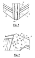
- FIGS. 7-9 illustrate the connection of the post to the frame using the connector assembly.
- FIG. 10 a cabinet constructed in accordance with the present invention.
- the cabinet 10 is provided with modular construction so that the cabinet 10 is typically configured for supporting electronic equipment 11, such as a server or telecom equipment.
- the cabinet 10 can be shipped when unassembled and then assembled on-site without any sacrifice of structural integrity or quality of the finally assembled cabinet 10.
- the cabinet 10 is typically supplied complete with front / rear doors, side panels, top and base plates, fan plate assembly, adjustable feet, grounding kit, depth members and adjustable mounting verticals.
- Other optional accessory parts including plain / vented front panels, cable trays, chassis runners, sliding shelves, fixed shelves, front stabilizing foot, and castors.
- the cabinet 10 is provided with two top / base frames 12.
- the top frame will be designated hereinafter as 12a, and the base frame will be designated hereinafter as 12b.
- the top frame 12a and the base frame 12b are identical in construction and function and thus, when referring in general to such construction, the top frame 12a or the base frame 12b will simply be referred to as the "frame 12".
- the cabinet 10 is also provided with one or more posts 16, and one or more connector assembly 18 (see FIG. 2).
- the connector assembly 18 connects the post 16 to the frame 12.
- the cabinet 10 can be characterized as a rectangular cabinet constructed of the top frame 12a, the base frame 12b, four posts 16 and eight connector assemblies 18.
- the top frame 12a and the base frame 12b substantially correspond in size and are both provided with a rectangular shape defining four corners 20 (only one of the corners 20 of the top frame and base frame 12a and 12b are designated herein for purposes of clarity.
- Each of the posts 16 is positioned adjacent to one of the corners 20 of the top frame 12a and the base frame 12b and extends between the top frame 12a and the base frame 12b.
- Two connector assemblies 18 are provided for connecting each of the posts 16 to the top frame 12a and the base frame 12b.
- the connector assembly 18 includes a corner gusset plate 24, and a corner clamp plate 26.
- the corner gusset plate 24 is rigidly supported by the frame 12.
- the corner clamp plate 26 is supported by the corner gusset plate 24 and spaced a distance therefrom to form a channel 28 between at least a portion of the corner gusset plate 24 and the corner clamp plate 26.
- At least a portion of the post 16 is positioned within the channel 28 and clamped between the corner gusset plate 24 and the corner clamp plate 26.
- the corner clamp plate 26 can be connected to the corner gusset plate 24 by a M12x25 button-head allen screw 27.
- corner gusset plate 24 can be connected to the corner clamp plate 26 by any other suitable method or assembly, such as a wingnut screw, a carriage screw, a clamping device, keys, magnets, or any other type of mechanical or magnetic assembly capable of changing the relative width of the channel 28 to clamp the post 16 as described herein.
- the frame 12 includes a horizontal wall 40 and a vertical sidewall 42.
- One or more slots 46 are formed in the horizontal wall 40 of the frame 12.
- the frame 12 is provided with four corners 20, and four slots 46 are formed in the horizontal wall 40 adjacent each of the corners 20.
- the horizontal wall 40 of the frame 12 includes sixteen slots 46.
- Each of the corner gusset plates 24 is provided with at least one tab 48 (FIG. 9) which is positioned within one of the slots 46.
- each of the corner gusset plates 24 is provided with four tabs 48 which correspond to the four slots 46 provided in each of the corners 20.
- the corner gusset plates 24 each include a vertical sidewall 50. At least one of the frame 12 and the corner gusset plate 24 have one or more holes 54 formed in the vertical sidewalls 42 and 50, and the other one of the frame 12 and the corner gusset plate 24 includes a semi-shear 58 positioned in the hole 54.
- each hole 54 is formed in the vertical sidewall 42 of the frame 12.
- the frame 12 is provided with a first end 62, an opposed second end 64, a first side 66, an opposed second side 68, and four vertical sidewalls 42.
- Two of the vertical sidewalls 42 extend generally between the first end 62 and the second end 64.
- the other two vertical sidewalls 42 extend generally between the first side 66 and the second side 68.
- Each vertical sidewall 42 has six holes 54 with three of the holes 54 in each vertical sidewall 42 being located adjacent to one of the corners 20.
- each corner gusset plate 24 has four semi-shears 58 connected to the vertical sidewall 50.
- each corner gusset plate 24 are disposed in four of the six holes 54 located adjacent to each corner 20.
- the other two holes 54 adjacent to each corner 20 receive a connecting device 70, such as a bolt, washer and nut, for connecting the vertical sidewalls 42 and 50 together.
- the semi-shear 58 functions to ensure the accurate placement / alignment of the corner gusset plate 24 in the corner positions. By ensuring accurate alignment of the corner gusset plate 24 in the top / bottom frame 12, the alignment of the corner posts 16 are guaranteed a precision fit.
- the corner gusset plate 24 is connected to the frame 12 by any suitable assembly such as glue, screws, magnets, or the like.
- the corner gusset plate 24 is provided with a horizontal plate 80.
- the horizontal plate 80 is rigidly connected to the horizontal wall 40 of the frame 12 via any suitable assembly 81, such as a bolt.
- the vertical sidewall 50 of the corner gusset plate 24 can be characterized as having at least two wall portions 86 and 88.
- the two wall portions 86 and 88 are disposed angularly with respect to each other such that the two wall portions 86 and 88 generally align with the vertical sidewall 42 of the frame 12.
- the wall portions 86 and 88 are disposed about 90° with respect to each other.
- the vertical sidewalls 42 and 50 of the frame 12 and the corner gusset plate 24 can be characterized as "mutually orthogonal vertical sidewalls".
- the vertical sidewall 50 is provided with a third wall portion 90 positioned in between the wall portions 86 and 88.
- the vertical sidewall 50 is formed of sheet metal which has been bent to form the wall portions 86, 88 and 90.
- the corner clamp plate 26 is supported by the wall portion 90 of the corner gusset plate 24.
- the post 16 includes a first end 100, an opposed second end 102, and one or more flanges 104 extending at least partly therebetween.
- the flange(s) 104 are sized and dimensioned to be inserted into the channel 28 formed between the corner clamp plate 26 and the corner gusset plate 24 to connect the post 16 to the frame 12.
- the first end 100 and the second end 102 of the post 16 are substantially identical in construction and function. Thus, only the first end 100 will be described hereinafter.
- the first end 100 of the post 16 includes a pair of recessed portions 108 separated from a medial portion 110 by a pair of shoulders 112. The size of the shoulders 112 can vary widely.
- the size of the shoulders 112 corresponds to the thickness of the horizontal wall 40 of the frame 12 such that the recessed portions 108 engage the horizontal wall 40 when the post 12 is positioned in an installed position (FIGS. 8 and 9) at the corner 20 of the frame 12.
- the post 16 can be provided with any suitable assembly for connecting the optional accessories discussed above to the post 16.
- the post 16 can be provided with a series of holes 120 so that certain of the optional accessories can be bolted directly to the post 16.
- the four corner gusset plates 24 are connected to the top frame 12a, and four corner gusset plates 24 are connected to the base frame 12b as described above.
- One of the corner clamp plates 26 is connected to each of the corner gusset plates 24 such that the corner clamp plates 26 are positioned a distance away from the corner gusset plate 24 and the channel 28 is formed between at least a portion of the corner gusset plate 24 and the corner clamp plate 26.
- At least a portion of each post 16 is positioned in the channel 28 and the corner clamp plate 26 is moved relative to the corner gusset plate 24 to clamp the post 16 between the corner clamp plate 26 and the corner gusset plate 24.
- the corner clamp plate 26 can be moved by tightening a screw. This procedure is then repeated seven more times to connect each of the four posts 16 to the top frame 12a and the base frame 12b.
- the frames 12a and 12b, the post 16, the corner gusset plate 24 and the corner clamp plate 26 are constructed of rigid materials, such as plastic, metal or polymeric materials.
- the frames 12a and 12b, the post 16, the corner gusset plate 24 and the corner clamp plate 26 are constructed of sheet metal manufactured using hard press tooling.
- the frame 12 can be constructed of 1.5 mm sheet steel
- the post 16 can be constructed of 1.5 mm sheet steel
- the corner gusset plate 24 can be constructed of 3.0 mm sheet steel
- the corner clamp plate 26 can be constructed of 3.0 mm sheet steel.
- the connector assembly 18 (or “corner assembly”) provides a very stable construction that reliably provides a precise fit. Because of how the parts are configured for the corners 20 of the rack frame 12, there is no tolerance buildup.
- top frame 12a to include top plate and fan plate
- bottom frame 12b to include bottom plate and adjustable feet
- side frames to include side panels, depth members, mounting verticals and cable trays
- the cabinet 10 is delivered to a customer with the corner assemblies 18 connected to the top frame 12a and the base frame 12b.
- the customer simply needs to slide the posts 16 into place and tighten the mechanism, such as a screw, controlling the distance between the corner clamp plate 26 and the corner gusset plate 24 to assemble the cabinet 10.
- the reliable precision fit aspect of the described embodiment means that unassembled shipping and on-site assembly can be carried out without any sacrifice of structural integrity or quality of the finally assembled rack frame product.
Landscapes
- Engineering & Computer Science (AREA)
- Power Engineering (AREA)
- Assembled Shelves (AREA)
- Connection Of Plates (AREA)
- Mutual Connection Of Rods And Tubes (AREA)
- Patch Boards (AREA)
- Casings For Electric Apparatus (AREA)
- Lock And Its Accessories (AREA)
- Control Of Motors That Do Not Use Commutators (AREA)
Claims (13)
- Schrank, der folgendes umfasst:einen Rahmen (12);einen Pfosten (16); undeine Verbindungseinheit (18), welche den Pfosten (16) mit dem Rahmen (12) verbinden kann, dadurch gekennzeichnet, dass die Verbindungseinheit folgendes umfasst:eine Eckversteifung (25), die präzise angeordnet ist und durch den Rahmen steif gestützt wird; undeine Klemmplatte (26), die durch die Eckversteifung (24) gestützt wird und von dieser räumlich getrennt angeordnet ist, so dass ein Kanal (28) zwischen mindestens einem Abschnitt der Eckversteifung (24) und der Klemmplatte (26) gebildet wird, wobei zumindest ein Abschnitt des Pfostens (16) in dem Kanal (28) positioniert ist und zwischen der Eckversteifung (24) und der Klemmplatte (26) geklemmt wird, wobeider genannte Abschnitt des Pfostens eine Struktur aufweist, welche die Montage des Pfostens (16) an dem Rahmen (12) ermöglicht, indem:zuerst die Klemmplatte (26) durch die Eckversteifung (24) gestützt wird, so dass der Kanal gebildet wird; undwobei danach der genannte Abschnitt des Pfostens (16) an die entsprechende Position in dem Kanal (28) geschoben wird.
- Schrank nach Anspruch 1, wobei der genannte Abschnitt des Pfostens (16) einen oder mehrere Flansche (104) aufweist, die sich zumindest teilweise zwischen den Enden des Pfostens (16) erstrecken; wobei der genannte eine oder die mehreren Flansche (104) für eine Einführung in den Kanal (28) bemessen und dimensioniert sind, wobei der Kanal zwischen der Klemmplatte (26) und der Eckversteifung (24) ausgebildet ist, um den Pfosten (16) mit dem Rahmen (12) zu verbinden.
- Schrank nach Anspruch 1 oder 2, wobei der Rahmen (12) eine horizontale Wand (40) und einen oder mehrere Schlitze (46) aufweist, die in der horizontalen Wand (40) ausgebildet sind, und wobei die Eckversteifung (24) mindestens einen Ansatz (48) aufweist, der in dem in dem Rahmen (12) ausgebildeten Schlitz (46) positioniert ist.
- Schrank nach einem der Ansprüche 1 bis 3, wobei der Rahmen (12) eine vertikale Seitenwand (42) aufweist, und wobei die Eckversteifung (24) eine vertikale Seitenwand (50) aufweist, wobei zumindest der Rahmen (12) oder die Eckversteifung (24) ein Loch (54) aufweist, das in der vertikalen Seitenwand ausgebildet ist, und wobei die jeweils andere Komponente von Rahmen und Eckversteifung eine Halbschereinrichtung (58) aufweist, die in dem Loch (54) positioniert ist.
- Schrank nach Anspruch 4, wobei der Rahmen (12) das Loch (54) aufweist, und wobei die Eckversteifung (24) die Halbschereinrichtung (58) aufweist.
- Schrank nach einem der Ansprüche 1 bis 5, wobei der Rahmen (12) und die Eckversteifung (24) orthogonale vertikale Seitenwände (42, 50) aufweisen, die angrenzend aneinander positioniert sind.
- Schrank nach einem der Ansprüche 1 bis 6, wobei der Rahmen (12) einen Eckausschnitt definiert, und wobei der Pfosten innerhalb zumindest einem Abschnitt des Eckausschnitts positioniert ist.
- Verfahren zur Konstruktion eines Schranks, wobei das Verfahren die folgenden Schritte umfasst:das Verbinden einer Eckversteifung (24) mit einem Rahmen (12);das Positionieren einer Klemmplatte (26) in einem Abstand von der Eckversteifung (24), so dass ein Kanal (28) zwischen mindestens einem Abschnitt der Eckversteifung (24) und der Klemmplatte (26) gebildet wird;das Positionieren zumindest eines Abschnitts eines Pfostens (16) in dem Kanal (28); unddas Bewegen der Klemmplatte (26) im Verhältnis zu der Eckversteifung (24), um den Pfosten (16) zwischen der Klemmplatte (26) und der Eckversteifung (24) zu klemmen.
- Verfahren nach Anspruch 8, wobei der Rahmen (12) eine horizontale Wand (40) und einen oder mehrere Schlitze (46) aufweist, die in der horizontalen Wand ausgebildet sind, und wobei das Verfahren ferner den Schritt des Positionierens eines Ansatzes (48) der Eckversteifung (249 in dem Schlitz (46) umfasst, der in dem Rahmen (12) ausgebildet ist.
- Verfahren nach einem der Ansprüche 8 bis 9, wobei der Rahmen (12) eine vertikale Seitenwand (42) aufweist, und wobei die Eckversteifung eine vertikale Seitenwand (50) aufweist, wobei mindestens der Rahmen (12) oder die Eckversteifung (24) ein in der vertikalen Seitenwand ausgebildetes Loch (54) aufweist, und wobei das Verfahren ferner den Schritt des Positionierens der jeweils anderen Komponente des Rahmens oder der Eckversteifung in dem Loch (54) umfasst.
- Verfahren nach Anspruch 10, wobei der Rahmen das Loch aufweist, und wobei die Eckversteifung eine Halbschereinrichtung (58) aufweist, die in dem Loch positioniert ist.
- Verfahren nach einem der Ansprüche 8 bis 11, wobei der Rahmen (12) und die Eckversteifung (245) orthogonale vertikale Seitenwände (42, 50) aufweisen, und wobei der Schritt des Verbindens der Eckversteifung (24) mit dem Rahmen (12) den Schritt des Positionierens der orthogonalen vertikalen Seitenwände (42, 50) angrenzend aneinander aufweist.
- Verfahren nach einem der Ansprüche 8 bis 12, wobei der Rahmen (12) einen Eckausschnitt definiert, und wobei der Schritt des Positionierens zumindest eines Abschnitts des Pfostens (16) in dem Kanal ferner definiert ist als das Positionieren zumindest eines Abschnitts des Pfostens in dem Eckausschnitt.
Applications Claiming Priority (3)
| Application Number | Priority Date | Filing Date | Title |
|---|---|---|---|
| US36839002P | 2002-03-28 | 2002-03-28 | |
| US368390P | 2002-03-28 | ||
| PCT/GB2003/001363 WO2003084298A2 (en) | 2002-03-28 | 2003-03-28 | Rack frame structure and method of assembling same |
Publications (2)
| Publication Number | Publication Date |
|---|---|
| EP1490936A2 EP1490936A2 (de) | 2004-12-29 |
| EP1490936B1 true EP1490936B1 (de) | 2007-07-04 |
Family
ID=28675478
Family Applications (1)
| Application Number | Title | Priority Date | Filing Date |
|---|---|---|---|
| EP03715112A Expired - Lifetime EP1490936B1 (de) | 2002-03-28 | 2003-03-28 | Rahmenstruktur und montageverfahren |
Country Status (9)
| Country | Link |
|---|---|
| US (3) | US20030214205A1 (de) |
| EP (1) | EP1490936B1 (de) |
| JP (1) | JP4069075B2 (de) |
| CN (1) | CN1703812B (de) |
| AT (1) | ATE366470T1 (de) |
| AU (1) | AU2003219304B2 (de) |
| DE (1) | DE60314739D1 (de) |
| ES (1) | ES2289277T3 (de) |
| WO (1) | WO2003084298A2 (de) |
Families Citing this family (39)
| Publication number | Priority date | Publication date | Assignee | Title |
|---|---|---|---|---|
| US20030214205A1 (en) * | 2002-03-28 | 2003-11-20 | Brendan Wyatt | Rack frame structure and method of assembling same |
| US6974036B2 (en) * | 2002-04-01 | 2005-12-13 | Viasystems Group, Inc. | Corner post and manufacturing process for making same |
| US20060117702A1 (en) * | 2004-12-06 | 2006-06-08 | Shih-Ming Lin | Table jointing device |
| ES2296442B1 (es) * | 2005-04-05 | 2009-03-16 | Rafael Gonzalez Llorens | Mesa, estanteria o estructura modular de perfiles huecos de seccion cuadrangular montados por acoplamiento con elementos retenedores de seguridad. |
| US20070170136A1 (en) * | 2006-01-25 | 2007-07-26 | Kenny Sean T | Modular outdoor kitchen systems |
| FR2914118B1 (fr) * | 2007-03-22 | 2009-04-17 | Schneider Electric Ind Sas | Pilier d'angle pour coffret electrique et coffret ainsi equipe |
| US20090283488A1 (en) | 2008-05-19 | 2009-11-19 | Chatsworth Products, Inc. | Seismically hardened two-post electronic equipment rack |
| FR2937114B1 (fr) * | 2008-10-13 | 2010-11-19 | Legrand France | Structure d'angle pour meuble metallique et application |
| CN101465089B (zh) * | 2008-12-17 | 2012-10-10 | 康佳集团股份有限公司 | 一种led显示屏模组 |
| TW201200073A (en) * | 2010-06-17 | 2012-01-01 | yong-yu Li | Assembly-type frame device |
| CN102316697A (zh) * | 2010-07-09 | 2012-01-11 | 鸿富锦精密工业(深圳)有限公司 | 机柜框架 |
| US8787023B2 (en) | 2010-09-10 | 2014-07-22 | Chatsworth Products, Inc. | Rail mounting clamp for electronic equipment enclosure |
| EP2429272A2 (de) | 2010-09-10 | 2012-03-14 | Chatsworth Products, Inc. | Kabeldurchlaufpaneel für Gehäuse eines elektronischen Geräts |
| US8901438B2 (en) | 2010-09-10 | 2014-12-02 | Chatsworth Products, Inc. | Electronic equipment cabinet structure |
| EP2525636B8 (de) * | 2011-05-16 | 2014-10-08 | Middle Atlantic Products, Inc. | Trägeranordnung |
| CA2793793C (en) * | 2011-10-28 | 2018-10-09 | Les Industries Cendrex Inc. | Access doors |
| DE102012001097B3 (de) | 2012-01-20 | 2013-04-25 | Rittal Gmbh & Co. Kg | Sockeleckstück für die Einhandmontage an einem Schaltschrank |
| US20140057767A1 (en) * | 2012-02-21 | 2014-02-27 | Coulter Ventures, LLC | Modular exercise platform |
| US8844736B1 (en) * | 2012-08-09 | 2014-09-30 | James Hangley | Method and stand apparatus for permanent creasing of articles of clothing including shirt sleeves, pants, and linen dress pants |
| US20140196394A1 (en) | 2013-01-11 | 2014-07-17 | Chatsworth Products, Inc. | Modular thermal isolation barrier for data processing equipment structure |
| US20140263129A1 (en) * | 2013-03-12 | 2014-09-18 | Ching-Chao Tseng | Rack assembly |
| CN106454174A (zh) * | 2013-07-02 | 2017-02-22 | 青岛海信电器股份有限公司 | 一种电视机 |
| US9351427B2 (en) | 2013-12-17 | 2016-05-24 | Chatsworth Products, Inc. | Electronic equipment enclosure |
| DE202014100664U1 (de) * | 2014-02-14 | 2014-02-24 | Aht Cooling Systems Gmbh | Kühlregal |
| DE102014102464B4 (de) * | 2014-02-25 | 2018-12-13 | Rittal Gmbh & Co. Kg | Eckverbinder zum Verbinden mindestens zweier senkrecht zueinander angeordneter Rahmenprofile eines Rahmengestells |
| US9301605B2 (en) * | 2014-03-13 | 2016-04-05 | Middle Atlantic Products, Inc. | Rack frame assembly |
| GB2528432B (en) * | 2014-05-30 | 2018-08-29 | Cannon Tech Limited | Rack assembly, method of assembly thereof and kit of parts for assembly thereof |
| CN104023501B (zh) * | 2014-07-02 | 2016-09-28 | 无锡康贝电子设备有限公司 | 拼装式机柜框架 |
| CN104648876B (zh) * | 2015-02-10 | 2017-01-04 | 苏州劲元油压机械有限公司 | 一种悬臂式货架的悬臂结构及其设置方法 |
| WO2017147665A1 (pt) * | 2016-03-04 | 2017-09-08 | Chung Kwo Tzuo | Suporte para perfil e parede lateral de display expositor, com sistema de montagem |
| US10368459B2 (en) | 2016-12-15 | 2019-07-30 | Raytheon Company | Equipment clamping assembly using clamps and friction to secure equipment for use in rugged and other environments |
| US10080306B2 (en) | 2016-12-15 | 2018-09-18 | Raytheon Company | Equipment clamping assembly having horizontal and vertical clamps for use in rugged and other environments |
| US10316509B2 (en) * | 2017-04-03 | 2019-06-11 | Revamp Panels, LLC | Post and beam system |
| CN109043821A (zh) * | 2018-08-07 | 2018-12-21 | 浙江建设职业技术学院 | 一种智能讲台用遮光保护罩及其制造方法 |
| US20200085192A1 (en) * | 2018-09-14 | 2020-03-19 | Quadrifoglio Partners Inc | Multifunctional furniture module |
| US20200149288A1 (en) | 2018-11-13 | 2020-05-14 | Katerra Inc. | Floor panel |
| KR102111394B1 (ko) * | 2019-08-22 | 2020-05-18 | 주식회사 한국창의교육 | 플레이트 연결 조립체 |
| JP7389612B2 (ja) * | 2019-10-28 | 2023-11-30 | 株式会社オカムラ | 什器 |
| CN113659463B (zh) * | 2021-09-17 | 2022-12-02 | 盐城春兴机械制造有限公司 | 一种组合式电气柜角撑架 |
Family Cites Families (30)
| Publication number | Priority date | Publication date | Assignee | Title |
|---|---|---|---|---|
| US858547A (en) * | 1907-03-20 | 1907-07-02 | Thorne Hold Fast Metal Bar Company | Window corner-post. |
| US2485172A (en) * | 1946-10-25 | 1949-10-18 | Samuel Stamping And Enameling | Furniture leg construction |
| US3229790A (en) * | 1961-01-30 | 1966-01-18 | Morris Norian | Tensioned frame structure |
| US3195196A (en) * | 1963-04-19 | 1965-07-20 | Vincent J Carisi | Corner fastening |
| US3275394A (en) * | 1964-08-03 | 1966-09-27 | Massinger Heinz | Furniture frame construction |
| US3353854A (en) * | 1965-04-09 | 1967-11-21 | Gen Electric | Structural corner assembly |
| US3370871A (en) * | 1965-08-20 | 1968-02-27 | Piarotto Ampelio | Device for joining panels, in particular wooden panels in the manufacture of compound furniture |
| US3769772A (en) * | 1969-10-30 | 1973-11-06 | Oetiker Hans | Structural assemblies |
| US3642310A (en) * | 1970-05-04 | 1972-02-15 | Keystone Lamp Mfg Corp | Corner joint assembly |
| DK136272B (da) * | 1974-10-11 | 1977-09-19 | Raaco Storage Systems As | Hjørnesamling i en byggereol og tilhørende samlingselement. |
| DE2515569B2 (de) * | 1975-04-10 | 1978-02-16 | Veyhl-Produktion KG, 7261 Zwerenberg | Verbindung fuer drei rohrabschnitte |
| US4078847A (en) * | 1976-05-11 | 1978-03-14 | Presnick Michael C | Electronic equipment enclosure |
| US4347015A (en) * | 1980-11-03 | 1982-08-31 | General Electric Company | Structural frame corner assembly for electrical switchboards and the like |
| FR2542046B1 (fr) * | 1983-01-13 | 1985-11-29 | Atal | Dispositif d'angle destine a l'assemblage d'un triedre de trois tubes |
| NO874024L (no) * | 1986-09-26 | 1988-03-28 | Vormet Quality Fab Close Corp | Ramme for elektrisk og elektronisk utstyr. |
| BR6900238U (pt) * | 1989-02-15 | 1990-11-20 | Sebastiao Ferreira Dias | Dispositivo fixadores de cantoneiras |
| GB2231117B (en) * | 1989-04-07 | 1992-08-12 | Marconi Co Ltd | Framework structure |
| US4954007A (en) * | 1989-05-08 | 1990-09-04 | Pinney Richard C | Framework for cabinet structure |
| US5020866A (en) * | 1989-11-13 | 1991-06-04 | Gichner Systems Group, Inc. | Enclosure for housing electronic components |
| FR2711454B1 (fr) * | 1993-10-18 | 1995-11-24 | Merlin Gerin | Liaison d'angle pour armoire, et armoire électrique comportant de telles liaisons. |
| US5639150A (en) * | 1995-09-22 | 1997-06-17 | Amco Engineering Co. | Electronic component enclosure and method |
| DE19536926C2 (de) * | 1995-10-04 | 1999-02-04 | Loh Kg Rittal Werk | Rahmenschenkel für einen Schaltschrank |
| DE19647791C2 (de) * | 1996-11-19 | 2002-06-13 | Rittal Gmbh & Co Kg | Eckverbindung für ein Rahmengestell |
| DE29623065U1 (de) * | 1996-11-19 | 1997-10-02 | Rittal-Werk Rudolf Loh GmbH & Co. KG, 35745 Herborn | Rahmenprofil für ein Rahmengestell eines Schaltschrankes |
| DE29623560U1 (de) * | 1996-11-19 | 1998-10-01 | Rittal-Werk Rudolf Loh GmbH & Co. KG, 35745 Herborn | Schaltschrank mit einem Rahmengestell |
| JP3523768B2 (ja) * | 1997-03-21 | 2004-04-26 | 三菱電機株式会社 | 組立式箱体 |
| US6379074B1 (en) * | 2000-05-08 | 2002-04-30 | Hsueh-Hung Chin | Coupler structure for steel pipe conjoinment stabilization |
| US6471434B2 (en) * | 2001-01-05 | 2002-10-29 | Hsueh-Hung Chin | Joint structure for strengthening steel pipe stability |
| DE20118376U1 (de) * | 2001-11-13 | 2002-01-24 | Roger Elektronikbauteile GmbH, 66131 Saarbrücken | Rahmengestell für einen Schaltschrank |
| US20030214205A1 (en) * | 2002-03-28 | 2003-11-20 | Brendan Wyatt | Rack frame structure and method of assembling same |
-
2003
- 2003-03-26 US US10/400,113 patent/US20030214205A1/en not_active Abandoned
- 2003-03-28 JP JP2003581559A patent/JP4069075B2/ja not_active Expired - Fee Related
- 2003-03-28 ES ES03715112T patent/ES2289277T3/es not_active Expired - Lifetime
- 2003-03-28 AT AT03715112T patent/ATE366470T1/de not_active IP Right Cessation
- 2003-03-28 WO PCT/GB2003/001363 patent/WO2003084298A2/en not_active Ceased
- 2003-03-28 CN CN03807258.0A patent/CN1703812B/zh not_active Expired - Fee Related
- 2003-03-28 EP EP03715112A patent/EP1490936B1/de not_active Expired - Lifetime
- 2003-03-28 AU AU2003219304A patent/AU2003219304B2/en not_active Ceased
- 2003-03-28 DE DE60314739T patent/DE60314739D1/de not_active Expired - Lifetime
-
2005
- 2005-12-09 US US11/299,614 patent/US7364243B2/en not_active Expired - Fee Related
-
2007
- 2007-05-23 US US11/752,611 patent/US20090001863A1/en not_active Abandoned
Also Published As
| Publication number | Publication date |
|---|---|
| JP4069075B2 (ja) | 2008-03-26 |
| CN1703812B (zh) | 2010-04-28 |
| EP1490936A2 (de) | 2004-12-29 |
| JP2005529480A (ja) | 2005-09-29 |
| US20090001863A1 (en) | 2009-01-01 |
| CN1703812A (zh) | 2005-11-30 |
| WO2003084298A3 (en) | 2004-05-13 |
| ATE366470T1 (de) | 2007-07-15 |
| US20060103274A1 (en) | 2006-05-18 |
| WO2003084298A2 (en) | 2003-10-09 |
| US20030214205A1 (en) | 2003-11-20 |
| ES2289277T3 (es) | 2008-02-01 |
| AU2003219304A1 (en) | 2003-10-13 |
| DE60314739D1 (de) | 2007-08-16 |
| AU2003219304B2 (en) | 2007-08-23 |
| US7364243B2 (en) | 2008-04-29 |
Similar Documents
| Publication | Publication Date | Title |
|---|---|---|
| EP1490936B1 (de) | Rahmenstruktur und montageverfahren | |
| US6974036B2 (en) | Corner post and manufacturing process for making same | |
| US9326413B2 (en) | Modular stackable shelving framework and equipment storage system | |
| AU2003241611B2 (en) | A cabinet and method for assembling the same | |
| US6601932B1 (en) | Close-off for use with an equipment rack | |
| US20020153814A1 (en) | Storage cabinet for electronic components | |
| CA1198803A (en) | Equipment cabinet | |
| US20170238438A1 (en) | Network element chassis tool and method for single person installation | |
| CA2962518A1 (en) | Multi-piece rack shelf | |
| EP4096374B1 (de) | Gestellanpassungsvorrichtung für ein gestell einer elektronische ausrüstung und adaptives gestellsystem damit | |
| JP2570191B2 (ja) | ラックマウント金具 | |
| JP3406545B2 (ja) | 組み立て部品ラックを覆うための組み立て要素セット | |
| HK1081331A (en) | Rack frame structure and method of assembling same | |
| US7891501B2 (en) | Shelf unit for use in rack for communication equipment | |
| CN218605942U (zh) | 一种货架 | |
| CN214510330U (zh) | 立柱及立柱柜 | |
| JP2705279B2 (ja) | 通信システム用架枠の構造 | |
| JPH0810296Y2 (ja) | 納骨壇 | |
| CN110799012B (zh) | 一种服务器机柜的安装主架及其安装方法 | |
| JP2724974B2 (ja) | 事務用棚 | |
| HK1077410A (zh) | 拐角支柱及其製造過程 |
Legal Events
| Date | Code | Title | Description |
|---|---|---|---|
| PUAI | Public reference made under article 153(3) epc to a published international application that has entered the european phase |
Free format text: ORIGINAL CODE: 0009012 |
|
| 17P | Request for examination filed |
Effective date: 20041022 |
|
| AK | Designated contracting states |
Kind code of ref document: A2 Designated state(s): AT BE BG CH CY CZ DE DK EE ES FI FR GB GR HU IE IT LI LU MC NL PT RO SE SI SK TR |
|
| AX | Request for extension of the european patent |
Extension state: AL LT LV MK |
|
| RAP1 | Party data changed (applicant data changed or rights of an application transferred) |
Owner name: VIASYSTEMS GROUP, INC. |
|
| RIN1 | Information on inventor provided before grant (corrected) |
Inventor name: WYATT, BRENDAN Inventor name: KIERNAN, BARRY |
|
| 17Q | First examination report despatched |
Effective date: 20060620 |
|
| GRAP | Despatch of communication of intention to grant a patent |
Free format text: ORIGINAL CODE: EPIDOSNIGR1 |
|
| GRAS | Grant fee paid |
Free format text: ORIGINAL CODE: EPIDOSNIGR3 |
|
| GRAA | (expected) grant |
Free format text: ORIGINAL CODE: 0009210 |
|
| AK | Designated contracting states |
Kind code of ref document: B1 Designated state(s): AT BE BG CH CY CZ DE DK EE ES FI FR GB GR HU IE IT LI LU MC NL PT RO SE SI SK TR |
|
| REG | Reference to a national code |
Ref country code: GB Ref legal event code: FG4D |
|
| REG | Reference to a national code |
Ref country code: CH Ref legal event code: EP |
|
| REG | Reference to a national code |
Ref country code: IE Ref legal event code: FG4D |
|
| REF | Corresponds to: |
Ref document number: 60314739 Country of ref document: DE Date of ref document: 20070816 Kind code of ref document: P |
|
| REG | Reference to a national code |
Ref country code: RO Ref legal event code: EPE |
|
| REG | Reference to a national code |
Ref country code: CH Ref legal event code: PL |
|
| PG25 | Lapsed in a contracting state [announced via postgrant information from national office to epo] |
Ref country code: SI Free format text: LAPSE BECAUSE OF FAILURE TO SUBMIT A TRANSLATION OF THE DESCRIPTION OR TO PAY THE FEE WITHIN THE PRESCRIBED TIME-LIMIT Effective date: 20070704 Ref country code: BG Free format text: LAPSE BECAUSE OF FAILURE TO SUBMIT A TRANSLATION OF THE DESCRIPTION OR TO PAY THE FEE WITHIN THE PRESCRIBED TIME-LIMIT Effective date: 20071004 Ref country code: PT Free format text: LAPSE BECAUSE OF FAILURE TO SUBMIT A TRANSLATION OF THE DESCRIPTION OR TO PAY THE FEE WITHIN THE PRESCRIBED TIME-LIMIT Effective date: 20071204 |
|
| REG | Reference to a national code |
Ref country code: ES Ref legal event code: FG2A Ref document number: 2289277 Country of ref document: ES Kind code of ref document: T3 |
|
| EN | Fr: translation not filed | ||
| PG25 | Lapsed in a contracting state [announced via postgrant information from national office to epo] |
Ref country code: AT Free format text: LAPSE BECAUSE OF FAILURE TO SUBMIT A TRANSLATION OF THE DESCRIPTION OR TO PAY THE FEE WITHIN THE PRESCRIBED TIME-LIMIT Effective date: 20070704 Ref country code: LI Free format text: LAPSE BECAUSE OF FAILURE TO SUBMIT A TRANSLATION OF THE DESCRIPTION OR TO PAY THE FEE WITHIN THE PRESCRIBED TIME-LIMIT Effective date: 20070704 Ref country code: CH Free format text: LAPSE BECAUSE OF FAILURE TO SUBMIT A TRANSLATION OF THE DESCRIPTION OR TO PAY THE FEE WITHIN THE PRESCRIBED TIME-LIMIT Effective date: 20070704 |
|
| PG25 | Lapsed in a contracting state [announced via postgrant information from national office to epo] |
Ref country code: BE Free format text: LAPSE BECAUSE OF FAILURE TO SUBMIT A TRANSLATION OF THE DESCRIPTION OR TO PAY THE FEE WITHIN THE PRESCRIBED TIME-LIMIT Effective date: 20070704 |
|
| PG25 | Lapsed in a contracting state [announced via postgrant information from national office to epo] |
Ref country code: GR Free format text: LAPSE BECAUSE OF FAILURE TO SUBMIT A TRANSLATION OF THE DESCRIPTION OR TO PAY THE FEE WITHIN THE PRESCRIBED TIME-LIMIT Effective date: 20071005 Ref country code: DK Free format text: LAPSE BECAUSE OF FAILURE TO SUBMIT A TRANSLATION OF THE DESCRIPTION OR TO PAY THE FEE WITHIN THE PRESCRIBED TIME-LIMIT Effective date: 20070704 |
|
| PLBE | No opposition filed within time limit |
Free format text: ORIGINAL CODE: 0009261 |
|
| STAA | Information on the status of an ep patent application or granted ep patent |
Free format text: STATUS: NO OPPOSITION FILED WITHIN TIME LIMIT |
|
| PG25 | Lapsed in a contracting state [announced via postgrant information from national office to epo] |
Ref country code: CZ Free format text: LAPSE BECAUSE OF FAILURE TO SUBMIT A TRANSLATION OF THE DESCRIPTION OR TO PAY THE FEE WITHIN THE PRESCRIBED TIME-LIMIT Effective date: 20070704 Ref country code: SK Free format text: LAPSE BECAUSE OF FAILURE TO SUBMIT A TRANSLATION OF THE DESCRIPTION OR TO PAY THE FEE WITHIN THE PRESCRIBED TIME-LIMIT Effective date: 20070704 |
|
| 26N | No opposition filed |
Effective date: 20080407 |
|
| PG25 | Lapsed in a contracting state [announced via postgrant information from national office to epo] |
Ref country code: SE Free format text: LAPSE BECAUSE OF FAILURE TO SUBMIT A TRANSLATION OF THE DESCRIPTION OR TO PAY THE FEE WITHIN THE PRESCRIBED TIME-LIMIT Effective date: 20071004 |
|
| PG25 | Lapsed in a contracting state [announced via postgrant information from national office to epo] |
Ref country code: FR Free format text: LAPSE BECAUSE OF FAILURE TO SUBMIT A TRANSLATION OF THE DESCRIPTION OR TO PAY THE FEE WITHIN THE PRESCRIBED TIME-LIMIT Effective date: 20080229 Ref country code: DE Free format text: LAPSE BECAUSE OF FAILURE TO SUBMIT A TRANSLATION OF THE DESCRIPTION OR TO PAY THE FEE WITHIN THE PRESCRIBED TIME-LIMIT Effective date: 20071005 |
|
| PG25 | Lapsed in a contracting state [announced via postgrant information from national office to epo] |
Ref country code: MC Free format text: LAPSE BECAUSE OF NON-PAYMENT OF DUE FEES Effective date: 20080331 Ref country code: FI Free format text: LAPSE BECAUSE OF NON-PAYMENT OF DUE FEES Effective date: 20080328 |
|
| GBPC | Gb: european patent ceased through non-payment of renewal fee |
Effective date: 20080328 |
|
| PGFP | Annual fee paid to national office [announced via postgrant information from national office to epo] |
Ref country code: NL Payment date: 20080922 Year of fee payment: 6 |
|
| PG25 | Lapsed in a contracting state [announced via postgrant information from national office to epo] |
Ref country code: EE Free format text: LAPSE BECAUSE OF FAILURE TO SUBMIT A TRANSLATION OF THE DESCRIPTION OR TO PAY THE FEE WITHIN THE PRESCRIBED TIME-LIMIT Effective date: 20070704 Ref country code: IE Free format text: LAPSE BECAUSE OF NON-PAYMENT OF DUE FEES Effective date: 20080328 |
|
| REG | Reference to a national code |
Ref country code: ES Ref legal event code: FD2A Effective date: 20080329 |
|
| PG25 | Lapsed in a contracting state [announced via postgrant information from national office to epo] |
Ref country code: GB Free format text: LAPSE BECAUSE OF NON-PAYMENT OF DUE FEES Effective date: 20080328 |
|
| PG25 | Lapsed in a contracting state [announced via postgrant information from national office to epo] |
Ref country code: ES Free format text: LAPSE BECAUSE OF NON-PAYMENT OF DUE FEES Effective date: 20080329 Ref country code: CY Free format text: LAPSE BECAUSE OF FAILURE TO SUBMIT A TRANSLATION OF THE DESCRIPTION OR TO PAY THE FEE WITHIN THE PRESCRIBED TIME-LIMIT Effective date: 20070704 |
|
| PG25 | Lapsed in a contracting state [announced via postgrant information from national office to epo] |
Ref country code: IT Free format text: LAPSE BECAUSE OF NON-PAYMENT OF DUE FEES Effective date: 20080328 |
|
| NLV4 | Nl: lapsed or anulled due to non-payment of the annual fee |
Effective date: 20091001 |
|
| PG25 | Lapsed in a contracting state [announced via postgrant information from national office to epo] |
Ref country code: RO Free format text: LAPSE BECAUSE OF NON-PAYMENT OF DUE FEES Effective date: 20070704 |
|
| PG25 | Lapsed in a contracting state [announced via postgrant information from national office to epo] |
Ref country code: NL Free format text: LAPSE BECAUSE OF NON-PAYMENT OF DUE FEES Effective date: 20091001 |
|
| PG25 | Lapsed in a contracting state [announced via postgrant information from national office to epo] |
Ref country code: LU Free format text: LAPSE BECAUSE OF NON-PAYMENT OF DUE FEES Effective date: 20080328 Ref country code: HU Free format text: LAPSE BECAUSE OF FAILURE TO SUBMIT A TRANSLATION OF THE DESCRIPTION OR TO PAY THE FEE WITHIN THE PRESCRIBED TIME-LIMIT Effective date: 20080105 |
|
| PG25 | Lapsed in a contracting state [announced via postgrant information from national office to epo] |
Ref country code: TR Free format text: LAPSE BECAUSE OF NON-PAYMENT OF DUE FEES Effective date: 20100914 |
|
| PG25 | Lapsed in a contracting state [announced via postgrant information from national office to epo] |
Ref country code: TR Free format text: LAPSE BECAUSE OF NON-PAYMENT OF DUE FEES Effective date: 20080328 |