EP1491082A1 - Procédé pour le nettoyage des outils de travail dans une machine agricole - Google Patents
Procédé pour le nettoyage des outils de travail dans une machine agricole Download PDFInfo
- Publication number
- EP1491082A1 EP1491082A1 EP04013454A EP04013454A EP1491082A1 EP 1491082 A1 EP1491082 A1 EP 1491082A1 EP 04013454 A EP04013454 A EP 04013454A EP 04013454 A EP04013454 A EP 04013454A EP 1491082 A1 EP1491082 A1 EP 1491082A1
- Authority
- EP
- European Patent Office
- Prior art keywords
- cleaning
- working
- crop
- grain tank
- tank emptying
- Prior art date
- Legal status (The legal status is an assumption and is not a legal conclusion. Google has not performed a legal analysis and makes no representation as to the accuracy of the status listed.)
- Granted
Links
- 238000004140 cleaning Methods 0.000 title claims abstract description 87
- 238000000034 method Methods 0.000 title claims abstract description 49
- 238000007664 blowing Methods 0.000 claims abstract description 9
- 210000000056 organ Anatomy 0.000 claims description 26
- 230000001960 triggered effect Effects 0.000 claims description 5
- 230000001419 dependent effect Effects 0.000 claims 1
- 238000003306 harvesting Methods 0.000 description 9
- 238000011109 contamination Methods 0.000 description 5
- 238000002360 preparation method Methods 0.000 description 5
- 239000010902 straw Substances 0.000 description 4
- 238000010586 diagram Methods 0.000 description 3
- 210000005069 ears Anatomy 0.000 description 3
- 241000209149 Zea Species 0.000 description 2
- 235000005824 Zea mays ssp. parviglumis Nutrition 0.000 description 2
- 235000002017 Zea mays subsp mays Nutrition 0.000 description 2
- 230000001133 acceleration Effects 0.000 description 2
- 235000005822 corn Nutrition 0.000 description 2
- 238000000926 separation method Methods 0.000 description 2
- 241000446313 Lamella Species 0.000 description 1
- 238000005520 cutting process Methods 0.000 description 1
- 230000000694 effects Effects 0.000 description 1
- 230000000977 initiatory effect Effects 0.000 description 1
- 239000000463 material Substances 0.000 description 1
- 230000003287 optical effect Effects 0.000 description 1
- 238000005457 optimization Methods 0.000 description 1
- 230000002035 prolonged effect Effects 0.000 description 1
- 238000010977 unit operation Methods 0.000 description 1
Images


Classifications
-
- A—HUMAN NECESSITIES
- A01—AGRICULTURE; FORESTRY; ANIMAL HUSBANDRY; HUNTING; TRAPPING; FISHING
- A01D—HARVESTING; MOWING
- A01D41/00—Combines, i.e. harvesters or mowers combined with threshing devices
- A01D41/12—Details of combines
-
- A—HUMAN NECESSITIES
- A01—AGRICULTURE; FORESTRY; ANIMAL HUSBANDRY; HUNTING; TRAPPING; FISHING
- A01F—PROCESSING OF HARVESTED PRODUCE; HAY OR STRAW PRESSES; DEVICES FOR STORING AGRICULTURAL OR HORTICULTURAL PRODUCE
- A01F12/00—Parts or details of threshing apparatus
- A01F12/44—Grain cleaners; Grain separators
- A01F12/444—Fanning means
Definitions
- the invention relates to a method for cleaning the organs within an agricultural machine, in particular a self-propelled combine.
- Different organs such as concaves, sieves, preparation trays and tray shakers, are arranged within a combine harvester. These organs are heavily stressed by the crop to be processed during harvesting and are accordingly heavily soiled. The organs must be kept clean to ensure optimal threshing, separation and further conveyance.
- the cleaning only refers to the sieves and does not extend to other work organs within the girls' harvester, which means that the sieves are cleaned immediately after cleaning are soiled again by the dirt adhering to other organs and become clogged in this way.
- the invention is therefore based on the object of providing a method for cleaning a plurality of organs within an agricultural machine, in particular a self-propelled combine harvester, which improves the method described at the outset and additionally relieves the driver of the agricultural machine.
- the object is achieved by a method for cleaning the organs within an agricultural machine according to the characterizing features of claim 1.
- an exact cleaning process can be determined without there being any crop loss.
- the at least one working element is the front attachment and its operating state is the standstill of the front attachment ensures that no new crop is fed to the agricultural harvesting machine.
- the cleaning process which is primarily carried out by blowing out the interior of the machine, can start, so that no threshed crop is carried out of the machine and the crop loss is kept low in this way.
- the grain tank emptying device can be considered as a further working organ, the operating state of which is the operation of the grain tank emptying device.
- the cleaning during the operation of the grain tank emptying device also avoids the loss of crop. This means that cleaning can take place safely in the state of the agricultural working machine and if there is no throughput, since then the crop that has already been harvested and is in the grain tank is no longer endangered by blowing it out and new crop does not get into the machine interior due to the lack of throughput.
- the cleaning can be carried out depending on different parameters, such as cutting unit operation, grain tank emptying operation, throughput quantity, position of the organs, type of crop or moisture conditions.
- the combination of the parameters can be adapted to the individual requirements. Due to a change in the parameters, an immediate setting can be made that is matched to the specific conditions, which results in an optimization of the cleaning process.
- the cleaning can be carried out automatically by arranging different sensors, such as optical dirt sensors, pressure sensors or crop loss sensors, within the agricultural machine and recording and transmitting the parameters to one Forward control unit. From there, cleaning can be started automatically.
- sensors such as optical dirt sensors, pressure sensors or crop loss sensors
- the driver can alternatively operate the cleaning manually as an alternative to the cleaning that starts automatically.
- the interior of the machine can be cleaned in a technically and structurally simple manner.
- the organs such as the sieves, the dirt is loosened before the actual cleaning process begins - which is done by generating winds - which simplifies blowing out.
- the cleaning process can also be done while the organs are being adjusted and even during the operation of the organs, but without throughput.
- the dirt is loosened by the constant movement and additionally removed by blowing out.
- the cleaning process can be carried out at intervals. This prevents dirt from accumulating due to prolonged use without cleaning.
- the cleaning device consisting of at least one blower can be arranged at different locations within the agricultural working machine.
- several cleaning devices can be integrated, in particular at the different locations susceptible to contamination. In this way, an effective and targeted cleaning of the entire interior of the machine can be carried out.
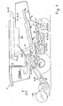
- FIG. 1 shows a schematic section through a combine harvester 1.
- the crop is cut by the front attachment 2 and fed to the following threshing elements 4 via the inclined conveyor 3.
- the strand of crop material is acted upon by the threshing drum 5, as a result of which the grains are separated therefrom and fall through the concave openings onto the preparation floor 7 arranged below the concave 6.
- the grains are conveyed against the direction of travel 8 of the combine harvester 1 by shaking movements.
- the main flow of the crop which mainly consists of straws, is passed between the threshing drum 5 and the concave 6 and passed through the subsequently arranged guide drum 9 to the separating device 10.
- FIG. 1 shows a schematic section through a combine harvester 1.
- the separating device 10 is designed as a possible exemplary embodiment as a step-shaped tray shaker 15.
- the separating device 10 can also be designed as an axial drum, not shown in the exemplary embodiment.
- the oscillating movements of the tray shaker 15 separate further grains and ears contained in the crop strand and feed them to the return floor 16 through openings within the tray shaker 15. From there, the seeds and ears of corn are transferred back to the preparation floor 7 in the direction of travel 8. Both the separated grains on the concave 6 and the crops transferred via the return floor 16 are then transferred to the cleaning units 17, while the straws of crop are conveyed to the end of the straw walker 15 and out of the rear part of the combine harvester 1 out of the combine harvester 1 on the ground fall.
- the cleaning units 17 consist of the top sieve 18 and the bottom sieve 19 and the cleaning fan 20.
- the top 18 and bottom sieve 19 is composed of adjustable fins, the air flow generated by the cleaning blower 20 these fins and that of the preparation base 7 crop falling on the top sieve 18 also passes through, as a result of which light non-grain components are conveyed out of the combine harvester 1. Heavier crop components, on the other hand, fall onto the top sieve 18 and are processed there by shaking movements.
- the grains separated in this way are fed to an elevator 30 via a guide plate 21, via which the grains are conveyed into the grain tank 25.
- the grains accumulated in the grain tank 25 can then be unloaded by means of a grain tank emptying device 22, for example on a transport vehicle (not shown).
- a grain tank emptying device 22 for example on a transport vehicle (not shown).
- these components are conveyed to the end of the sieve by the shaking movement of the top sieve 18 and from there pass via a guide plate 21 as a return via a further elevator 29 to the pre-acceleration drum 23 and pass through the threshing - and separation process a second time.
- sensors 24 at different locations on the combine harvester 1, which sensors detect, for example, the degree of contamination within the combine harvester 1.
- pressure sensors 24 can be sensitive to contamination Places are arranged within the combine harvester, which for example sense the blockages within the sieves 18, 19.
- Well-known sensors 24, which measure the layer thickness in the feed channel, can be used to detect the crop throughput. Due to the heavy contamination, the crop loss increases, since the grains are no longer optimally separated and, in some cases, can no longer pass through the sieve openings and fall over the cleaning device as a loss from the combine harvester 1.
- generally known loss sensors 24 - usually designed as baffle plates - can sense the number of grains falling out, which also allows conclusions to be drawn about the contamination.
- the signals generated by the sensors 24 can then automatically trigger a cleaning process or indicate to the driver of the agricultural working machine in the driver's cab that he has to initiate a cleaning cycle as soon as possible.
- the cleaning takes place in the form of a blowing out of the machine interior 26.
- the wind power required for this is generated by the cleaning fan 20.
- the drive of the cleaning fan 20 can be carried out as a function of the speed of the threshing elements 4 or completely independently of other machine components.
- the sieve openings can be adjusted during cleaning so that the dirt stuck between the lamellae is loosened by widening the sieve openings.
- all organs within the combine harvester 1 can be in operation in order to be able to convey residual crop components more easily through the air flow outside the machine area. It is also conceivable to position several cleaning fans at different locations within the combine.
- FIG. 2 shows a flow diagram according to which the method according to the invention works.
- the cleaning process takes place as a function of previously defined operating states of one or more working elements 28 and / or if there is no crop throughput.
- the working elements 28 are, for example, the threshing elements 4, the threshing drum 5, the guide drum 9, the separating device 10, the cleaning units 17, 18, 19 and the pre-acceleration drum 23 into consideration.
- the attachment 2 and the grain tank emptying device 22 are to be considered as essential working elements 28, the operating state of the attachment 2 being the standstill of the attachment 2 and the operating state of the grain tank emptying device 22 being their operation.
- the cleaning triggered does not only extend to the working members 28, but also to the entire area of the combine harvester 1 that is enclosed by the body.
- the cleaning process can be triggered automatically or manually by the driver of the agricultural working machine.
- the prerequisite is first that the combine harvester 1 is in harvesting mode, ie at least the threshing elements 4 of the combine harvester 1 are switched on. If this is the case, then in a step S 1 the sensors 24 arranged inside the combine 1 check whether the crop - crop throughput - is inside the combine 1, which still has to go through the threshing and cleaning process. If this is the case, no cleaning can take place. If the crop throughput is not present, it can be checked in a further step S 2 whether the header 2 is in operation or not. If the attachment 2 is not switched on and there is no crop throughput, the automatic organ cleaning starts.
- step S 3 whether the grain tank emptying device 22 is in operation. If the grain tank emptying device 22 is operated, the cleaning of the organs begins automatically. There can also be no loss here, since the grain that has already been harvested and cleaned has been conveyed into the grain tank and can no longer be lost by blowing it out. This further link serves as a safety circuit in order to achieve crop loss-free cleaning. If the grain tank emptying is not switched on, the cycle is repeated. In this case, cleaning does not take place.
- cleaning can take place when the combine harvester 1 is at a standstill. Insofar as the combine harvester 1 does not move, no crop can be forcibly harvested, so that cleaning can also take place in this constellation. Cleaning when the combine harvester 1 is at a standstill, for example after the entire harvesting process has ended, is required to shut down a clean machine, or else before the start of a new harvesting process in order to start harvesting with a cleaned machine.
- the combine harvester 1 is permanently cleaned by regular cleaning, so that soiling is removed relatively promptly and, as a result, larger soiling cannot occur at all.
- This has the advantage that lower engine speeds are required, which are required for generating the air currents of the cleaning device, since a lower air flow is necessary for less heavy soiling. Damage caused by stuck foreign bodies on the screen lamellas is also prevented.
- FIG. 3 shows a flow diagram according to which the organ cleansing is carried out on the basis of a process previously initiated manually by the driver.
- the condition is that the combine harvester 1 is in harvesting mode and there is no throughput.
- the attachment 2 is switched off by a step AS 1 by manual actuation.
- the grain tank emptying device 22 can be switched on by manual actuation in a step AS 2 which is independent of the step AS 1.
- organ cleansing automatically begins in one work step AS 3. This cleaning can consist of a single pass in one step AS 4. However, any extension of the cleaning phase is also conceivable.
- the organ cleansing stops in a work step AS 5.
- the driver can switch on the front attachment or, in a work step AS 7, switch off the grain tank emptying device 22 and start harvesting again.
- this variant has the advantage that cleaning is event-controlled, i.e. the organ cleansing is triggered by the driver after initiation of a certain process, whereas the work process shown in FIG. 2 runs through a continuous loop.
- the cleaning process can be stopped automatically by abruptly terminating the grain tank emptying or by switching the attachment 2 on again.
Landscapes
- Life Sciences & Earth Sciences (AREA)
- Environmental Sciences (AREA)
- Harvester Elements (AREA)
- Combines (AREA)
- Outside Dividers And Delivering Mechanisms For Harvesters (AREA)
Applications Claiming Priority (2)
| Application Number | Priority Date | Filing Date | Title |
|---|---|---|---|
| DE10328735 | 2003-06-25 | ||
| DE2003128735 DE10328735A1 (de) | 2003-06-25 | 2003-06-25 | Verfahren zur Reinigung der Organe innerhalb einer landwirtschaftlichen Arbeitsmaschine |
Publications (3)
| Publication Number | Publication Date |
|---|---|
| EP1491082A1 true EP1491082A1 (fr) | 2004-12-29 |
| EP1491082B1 EP1491082B1 (fr) | 2006-05-31 |
| EP1491082B2 EP1491082B2 (fr) | 2009-08-19 |
Family
ID=33394990
Family Applications (1)
| Application Number | Title | Priority Date | Filing Date |
|---|---|---|---|
| EP04013454A Expired - Lifetime EP1491082B2 (fr) | 2003-06-25 | 2004-06-08 | Procédé pour le nettoyage des outils de travail dans une machine agricole |
Country Status (2)
| Country | Link |
|---|---|
| EP (1) | EP1491082B2 (fr) |
| DE (2) | DE10328735A1 (fr) |
Cited By (3)
| Publication number | Priority date | Publication date | Assignee | Title |
|---|---|---|---|---|
| EP2774474B1 (fr) * | 2013-03-08 | 2019-12-11 | CLAAS Selbstfahrende Erntemaschinen GmbH | Moissonneuse-batteuse |
| US20200196531A1 (en) * | 2018-12-19 | 2020-06-25 | Agco International Gmbh | Combine harvester and method of controlling such |
| WO2023203413A1 (fr) * | 2022-04-21 | 2023-10-26 | Agco Corporation | Système de nettoyage pour un agencement de capteur |
Families Citing this family (1)
| Publication number | Priority date | Publication date | Assignee | Title |
|---|---|---|---|---|
| DE102013104121A1 (de) | 2013-04-24 | 2014-10-30 | Claas Selbstfahrende Erntemaschinen Gmbh | Landwirtschaftliche Erntemaschine |
Citations (4)
| Publication number | Priority date | Publication date | Assignee | Title |
|---|---|---|---|---|
| GB376781A (en) * | 1931-04-13 | 1932-07-13 | Harold Baron | Improvements in and relating to threshing machines |
| US2501906A (en) * | 1945-10-25 | 1950-03-28 | Lorenz Hans | Combine pickup cleaner |
| US3199125A (en) * | 1961-07-11 | 1965-08-10 | Harry E Mccullough | Corn picker rolls cleaner |
| EP0104676A2 (fr) | 1982-08-30 | 1984-04-04 | New Holland Inc. | Réglage automatique des grilles de nettoyage pour moissonneuse-batteuse |
Family Cites Families (3)
| Publication number | Priority date | Publication date | Assignee | Title |
|---|---|---|---|---|
| DE10030262A1 (de) † | 2000-06-20 | 2002-01-31 | Deere & Co | Reinigungseinrichtung |
| US6736722B1 (en) † | 2002-12-04 | 2004-05-18 | Deere & Company | Unloader tube cleaning system for harvesting apparatus |
| US6800025B2 (en) † | 2002-12-04 | 2004-10-05 | Deere & Co. | Combine air system for cleanout |
-
2003
- 2003-06-25 DE DE2003128735 patent/DE10328735A1/de not_active Withdrawn
-
2004
- 2004-06-08 EP EP04013454A patent/EP1491082B2/fr not_active Expired - Lifetime
- 2004-06-08 DE DE200450000647 patent/DE502004000647D1/de not_active Expired - Lifetime
Patent Citations (4)
| Publication number | Priority date | Publication date | Assignee | Title |
|---|---|---|---|---|
| GB376781A (en) * | 1931-04-13 | 1932-07-13 | Harold Baron | Improvements in and relating to threshing machines |
| US2501906A (en) * | 1945-10-25 | 1950-03-28 | Lorenz Hans | Combine pickup cleaner |
| US3199125A (en) * | 1961-07-11 | 1965-08-10 | Harry E Mccullough | Corn picker rolls cleaner |
| EP0104676A2 (fr) | 1982-08-30 | 1984-04-04 | New Holland Inc. | Réglage automatique des grilles de nettoyage pour moissonneuse-batteuse |
Cited By (4)
| Publication number | Priority date | Publication date | Assignee | Title |
|---|---|---|---|---|
| EP2774474B1 (fr) * | 2013-03-08 | 2019-12-11 | CLAAS Selbstfahrende Erntemaschinen GmbH | Moissonneuse-batteuse |
| US20200196531A1 (en) * | 2018-12-19 | 2020-06-25 | Agco International Gmbh | Combine harvester and method of controlling such |
| US11582915B2 (en) * | 2018-12-19 | 2023-02-21 | Agco International Gmbh | Combine harvester and method of controlling a combine harvester |
| WO2023203413A1 (fr) * | 2022-04-21 | 2023-10-26 | Agco Corporation | Système de nettoyage pour un agencement de capteur |
Also Published As
| Publication number | Publication date |
|---|---|
| DE10328735A1 (de) | 2005-02-10 |
| DE502004000647D1 (de) | 2006-07-06 |
| EP1491082B1 (fr) | 2006-05-31 |
| EP1491082B2 (fr) | 2009-08-19 |
Similar Documents
| Publication | Publication Date | Title |
|---|---|---|
| EP3662741B2 (fr) | Machine de travail agricole ainsi que procédé de fonctionnement d'une machine de travail agricole | |
| EP3560314B1 (fr) | Mécanisme de coupe à réglage automatique de l'orientation de dent de rabatteur | |
| DE602004005553T2 (de) | System zum Ausstossen von Ernteresten aus einem Mähdrescher | |
| EP1425956B1 (fr) | Moissonneuse-batteuse avec hache-paille | |
| EP2837280B2 (fr) | Moissonneuse-batteuse équipée d'un dispositif de hache-paille | |
| EP1358789B1 (fr) | Moissonneuse-batteuse avec hache-paille | |
| EP1493318B1 (fr) | Procédé de control d'un ensemble de battage pour moissonneuse-batteuse | |
| EP1350424B1 (fr) | Moisonneuse-batteuse avec dispositif de guidage de paille motorisé ajustable | |
| EP1442649B1 (fr) | Moissonneuse-batteuse et hache-paille | |
| DE102011085977A1 (de) | Sieb für eine Reinigungseinrichtung eines Mähdreschers | |
| DE102007046678A1 (de) | Landwirtschaftliches Arbeitsfahrzeug | |
| DE10147733A1 (de) | Verfahren und Vorrichtung zur Ermittlung einer Erntemaschineneinstellung | |
| DE102011052282A1 (de) | Reinigungssensor zur Steuerung der Erntegut- und Gebläsedruckverteilung | |
| DE102023127392A1 (de) | System und Verfahren zur automatischen Einstellung von Deckplatten | |
| DE102011052280A1 (de) | Vermeidung von Reinigungsverlusten bei starker Seitenneigung | |
| DE102020204859A1 (de) | Erntesteuerungssystem mit messerbalken-lasterfassung | |
| DE102015220561A1 (de) | Mähdrescher mit Reinigungsentlüftung durch ein von der Strohhäckslerwelle angetriebenes Sauggebläse | |
| EP2848113B1 (fr) | Dispositif de nettoyage pour une moissonneuse-batteuse | |
| EP1491082B2 (fr) | Procédé pour le nettoyage des outils de travail dans une machine agricole | |
| DE10359398B3 (de) | Erntegutbergungseinrichtung mit Abstreifelementen | |
| DE102020123939A1 (de) | Rotierender siebkasten | |
| DE102020207821A1 (de) | Mähdrescher mit einem vordrescher | |
| EP1470749B1 (fr) | Système batteur-séparateur | |
| DE19647433A1 (de) | Verfahren und Vorrichtung zum Hanfdrusch mit Schleppergeräten | |
| DE102011017620A1 (de) | Reinigungseinrichtung eines Mähdreschers |
Legal Events
| Date | Code | Title | Description |
|---|---|---|---|
| PUAI | Public reference made under article 153(3) epc to a published international application that has entered the european phase |
Free format text: ORIGINAL CODE: 0009012 |
|
| AK | Designated contracting states |
Kind code of ref document: A1 Designated state(s): AT BE BG CH CY CZ DE DK EE ES FI FR GB GR HU IE IT LI LU MC NL PL PT RO SE SI SK TR |
|
| AX | Request for extension of the european patent |
Extension state: AL HR LT LV MK |
|
| 17P | Request for examination filed |
Effective date: 20050629 |
|
| AKX | Designation fees paid |
Designated state(s): BE DE FR GB |
|
| GRAP | Despatch of communication of intention to grant a patent |
Free format text: ORIGINAL CODE: EPIDOSNIGR1 |
|
| GRAS | Grant fee paid |
Free format text: ORIGINAL CODE: EPIDOSNIGR3 |
|
| GRAA | (expected) grant |
Free format text: ORIGINAL CODE: 0009210 |
|
| AK | Designated contracting states |
Kind code of ref document: B1 Designated state(s): BE DE FR GB |
|
| REG | Reference to a national code |
Ref country code: GB Ref legal event code: FG4D Free format text: NOT ENGLISH |
|
| REF | Corresponds to: |
Ref document number: 502004000647 Country of ref document: DE Date of ref document: 20060706 Kind code of ref document: P |
|
| GBT | Gb: translation of ep patent filed (gb section 77(6)(a)/1977) |
Effective date: 20060615 |
|
| ET | Fr: translation filed | ||
| PLBI | Opposition filed |
Free format text: ORIGINAL CODE: 0009260 |
|
| PLAX | Notice of opposition and request to file observation + time limit sent |
Free format text: ORIGINAL CODE: EPIDOSNOBS2 |
|
| 26 | Opposition filed |
Opponent name: DEERE & COMPANY Effective date: 20070219 |
|
| PLBB | Reply of patent proprietor to notice(s) of opposition received |
Free format text: ORIGINAL CODE: EPIDOSNOBS3 |
|
| PUAH | Patent maintained in amended form |
Free format text: ORIGINAL CODE: 0009272 |
|
| STAA | Information on the status of an ep patent application or granted ep patent |
Free format text: STATUS: PATENT MAINTAINED AS AMENDED |
|
| 27A | Patent maintained in amended form |
Effective date: 20090819 |
|
| AK | Designated contracting states |
Kind code of ref document: B2 Designated state(s): BE DE FR GB |
|
| REG | Reference to a national code |
Ref country code: FR Ref legal event code: PLFP Year of fee payment: 13 |
|
| REG | Reference to a national code |
Ref country code: FR Ref legal event code: PLFP Year of fee payment: 14 |
|
| PGFP | Annual fee paid to national office [announced via postgrant information from national office to epo] |
Ref country code: GB Payment date: 20170620 Year of fee payment: 14 |
|
| REG | Reference to a national code |
Ref country code: FR Ref legal event code: PLFP Year of fee payment: 15 |
|
| GBPC | Gb: european patent ceased through non-payment of renewal fee |
Effective date: 20180608 |
|
| REG | Reference to a national code |
Ref country code: DE Ref legal event code: R084 Ref document number: 502004000647 Country of ref document: DE |
|
| PG25 | Lapsed in a contracting state [announced via postgrant information from national office to epo] |
Ref country code: GB Free format text: LAPSE BECAUSE OF NON-PAYMENT OF DUE FEES Effective date: 20180608 |
|
| P01 | Opt-out of the competence of the unified patent court (upc) registered |
Effective date: 20230512 |
|
| PGFP | Annual fee paid to national office [announced via postgrant information from national office to epo] |
Ref country code: FR Payment date: 20230622 Year of fee payment: 20 Ref country code: DE Payment date: 20230620 Year of fee payment: 20 |
|
| PGFP | Annual fee paid to national office [announced via postgrant information from national office to epo] |
Ref country code: BE Payment date: 20230620 Year of fee payment: 20 |
|
| REG | Reference to a national code |
Ref country code: DE Ref legal event code: R071 Ref document number: 502004000647 Country of ref document: DE |
|
| REG | Reference to a national code |
Ref country code: BE Ref legal event code: MK Effective date: 20240608 |