EP3560314B1 - Mécanisme de coupe à réglage automatique de l'orientation de dent de rabatteur - Google Patents
Mécanisme de coupe à réglage automatique de l'orientation de dent de rabatteur Download PDFInfo
- Publication number
- EP3560314B1 EP3560314B1 EP19169583.2A EP19169583A EP3560314B1 EP 3560314 B1 EP3560314 B1 EP 3560314B1 EP 19169583 A EP19169583 A EP 19169583A EP 3560314 B1 EP3560314 B1 EP 3560314B1
- Authority
- EP
- European Patent Office
- Prior art keywords
- reel
- actuator
- crop
- cutting unit
- cutting
- Prior art date
- Legal status (The legal status is an assumption and is not a legal conclusion. Google has not performed a legal analysis and makes no representation as to the accuracy of the status listed.)
- Active
Links
Images

Classifications
-
- A—HUMAN NECESSITIES
- A01—AGRICULTURE; FORESTRY; ANIMAL HUSBANDRY; HUNTING; TRAPPING; FISHING
- A01D—HARVESTING; MOWING
- A01D34/00—Mowers; Mowing apparatus of harvesters
- A01D34/01—Mowers; Mowing apparatus of harvesters characterised by features relating to the type of cutting apparatus
- A01D34/02—Mowers; Mowing apparatus of harvesters characterised by features relating to the type of cutting apparatus having reciprocating cutters
- A01D34/28—Adjusting devices for the cutter-bar
- A01D34/283—Adjustment of the cutter bar in a vertical plane, i.e. to adjust the angle between the cutter bar and the soil
-
- A—HUMAN NECESSITIES
- A01—AGRICULTURE; FORESTRY; ANIMAL HUSBANDRY; HUNTING; TRAPPING; FISHING
- A01D—HARVESTING; MOWING
- A01D41/00—Combines, i.e. harvesters or mowers combined with threshing devices
- A01D41/12—Details of combines
- A01D41/14—Mowing tables
- A01D41/141—Automatic header control
-
- A—HUMAN NECESSITIES
- A01—AGRICULTURE; FORESTRY; ANIMAL HUSBANDRY; HUNTING; TRAPPING; FISHING
- A01D—HARVESTING; MOWING
- A01D57/00—Delivering mechanisms for harvesters or mowers
- A01D57/01—Devices for leading crops to the mowing apparatus
- A01D57/02—Devices for leading crops to the mowing apparatus using reels
- A01D57/03—Devices for leading crops to the mowing apparatus using reels with supplementary controlled movement of the crop-engaging members, e.g. of the tines
-
- A—HUMAN NECESSITIES
- A01—AGRICULTURE; FORESTRY; ANIMAL HUSBANDRY; HUNTING; TRAPPING; FISHING
- A01D—HARVESTING; MOWING
- A01D57/00—Delivering mechanisms for harvesters or mowers
- A01D57/12—Rotating rakes
Definitions
- the present invention relates to a harvesting machine with a cutting unit which is equipped with a cutter bar for cutting crops from a field, a reel with reel tines arranged above the cutter bar and a cross conveyor for conveying the cut crops to a rear discharge opening, wherein the reel comprises reel arms which can be driven about a rotation axis, reel tine carriers which are supported on the reel arms so as to be rotatable about their longitudinal axes and have reel tines attached thereto, and an externally powered actuator connected to an electronic control unit for adjusting the angle of rotation of the reel tine carriers relative to the reel arms, and the electronic control unit can be operated to adjust the actuator depending on at least one property of the crop to be harvested.
- Headers are used in agriculture as harvesting headers on self-propelled harvesters when harvesting grain, usually combine harvesters, although they can also be used as harvesting headers on forage harvesters, for example when harvesting whole crop silage.
- Headers comprise a knife bar, a reel above it, and a cross conveyor which delivers the cut crop to a combine harvester's inclined conveyor or forage harvester's intake conveyor.
- the reel is designed to reach into the standing crop and feed it backwards so that it can be cut by the knife bar and picked up by the cross conveyor.
- the reel typically comprises a number of reel tine carriers attached to reel arms which in turn can be rotated about a central axis extending in the transverse direction. Reel tines are attached to the reel tine carriers.
- the orientation of the fingers over a rotation in the prior art is not radial to the axis of rotation of the reel arms, but essentially oriented downwards, which is achieved by a suitable control, for example using cam tracks ( US 6 170 244 B1 ) or chains ( DE 1 047 516 B ) or gears ( WO 2016/101059 A1 ) can scan a suitably shaped presetting device, e.g. in the form of a control cam.
- Harvesting threshed crops with high throughput and high quality starts at the cutting unit.
- the reel supports the intake of grain and correct use contributes significantly to an even material flow and low cutting unit losses.
- high cutting unit losses can occur and the uneven material flow can impair the function of all subsequent threshing and separating devices are negatively affected, reducing the efficiency of the entire combine harvester.
- the correct adjustment of all adjustable reel parameters requires a lot of experience from the machine operator.
- crops with uniform disturbances over large areas are rare (e.g. lodging grain), but fields with different crop characteristics in adjacent areas are more common (e.g. grain flattened by weather or wild animals).
- the operator would then have to adjust several reel parameters simultaneously in a short space of time. This is becoming increasingly difficult due to ever higher harvesting speeds and ever wider cutting units.
- the adjustable parameters of the reel are the speed, the height and the forward position.
- an automatic adjustment of these parameters based on sensed crop parameters, such as crop height has already been proposed (EP 2 517 549 A1 , DE 10 2016 118 637 A1 ), or a setting of these sizes depending on the cutting height ( EP 0 812 530 A1 ) or an adjustment of the position of the reel in case of cutting losses, which are detected by a camera ( DE 10 2016 202 628 A1 ).
- the DE 10 2016 215 197 A1 an automatic adjustment of an unspecified working parameter of a harvesting header in the event of sensory detection of lodged grain.
- Another adjustable size of the cutting unit is the orientation of the reel tines around the rotation axis of the reel tine carriers.
- this adjustment is carried out by mechanically adjusting a lever attached to the reel (see, for example, DE 1 047 516 B ) to adapt the orientation of the reel tines to the type of crop and conditions.
- a change during the harvesting process is therefore not possible or only possible with a great deal of time and effort, even if the conditions in a field should change during the harvest.
- the US 8 800 256 B2 describes a reel arrangement with a reel tine angle adjustment ring that is adjustable by an actuator to adjust the angle of the reel tines during rotation.
- the adjustment is carried out by an operator in the cab of the combine harvester or automatically based on the forward speed of the combine harvester or the speed of the reel or the density of the crop.
- a remote-controlled adjustment of the orientation of the reel tines is also used in the EP 1 297 735 A1 mentioned, but with the remark that automation of the independent adjustment of the angle of rotation of all reel tine carriers is less desirable due to the high complexity.
- the DE 24 11 153 A1 a cutting unit on a combine harvester in which the height of the reel is automatically controlled by a light barrier at the top of the crop. If the reel is moved all the way down for stored grain, a mechanical forced coupling automatically adjusts the angle of the reel tines backwards in order to better pick up the crop.
- the orientation of the reel teeth can only be changed manually or ( US 8 800 256 B2 ) to adjust them automatically depending on the throughput, the density of the crop or other field conditions or the forward speed of the combine harvester or ( DE 24 11 153 A1 ) by means of a mechanical coupling with the reel height for stored grain. This does not result in optimal acceptance of the harvested crop in all cases.
- reel parameters that are currently available for stored grain ( EP 0 812 530 A1 ) or funding problems ( DE 10 2016 202 628 A1 ), but the orientation of the reel tines is not varied.
- a harvesting machine is equipped with a cutting unit which is provided with a knife bar for cutting crops from a field, a reel with reel tines arranged above the knife bar and a cross conveyor for conveying the cut crops to a rear discharge opening.
- the reel comprises reel arms which can be driven about a rotation axis, reel tine carriers which are supported on the reel arms so as to be rotatable about their longitudinal axes and have reel tines attached to them, and an externally powered actuator connected to an electronic control unit for adjusting the angle of rotation of the reel tine carriers relative to the reel arms.
- the electronic control unit can be operated to adjust the actuator depending on at least one property of the crop to be harvested.
- the characteristics of the crop to be harvested concern the orientation of the crop stalks, i.e. whether it is standing or lying crop (stored grain) and, in the latter case, possibly also the direction in which the stored grain lies and/or a disturbance in the Material flow of the crop in the receiving area of the cutting unit between the knife bar and the cross conveyor, in particular possible conveying problems on the knife bar, on the cross conveyor or in between or winding of the reel.
- the system is particularly suitable for collecting stored grain and is most effective when used in conjunction with an optical sensor that can detect areas of stored grain in the field before the cutting unit and the orientation of the stored grain.
- an optical sensor that can detect areas of stored grain in the field before the cutting unit and the orientation of the stored grain.
- this or an additional optical sensor can also monitor the area around the cutter bar up to the cross conveyor screw for even material flow or for blockages. This sensor should also detect whether the reel is starting to wind or whether cut grain is being thrown back forward via the reel.
- the electronic control unit is connected to a sensor for detecting stored grain located in front of the cutting unit and its orientation and/or a stored map in which positions of stored grain located in front of the cutting unit and its orientation are stored and/or a sensor for detecting irregularities in the conveying behavior of the crop in the receiving area of the cutting unit and is operable to control the actuator depending on the map and/or the signals from at least one of the sensors.
- the electronic control unit can therefore be operated to control the actuator depending on the presence and orientation of stored grain to be picked up.
- the control unit may be operable to control further actuators for adjusting the cutting unit height and/or the position of the reel in the forward direction and/or the position of the reel in the vertical direction and/or the speed of rotation of the reel based on signals from at least one sensor and/or data entered in the map.
- the cutting unit is used in conjunction with a harvesting machine, which can be a combine harvester or a forage harvester.
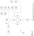
- the Figure 1 shows a self-propelled harvesting machine 10 in the manner of a combine harvester. It comprises a supporting chassis 12, which is supported on the ground by drivable front wheels 12 and steerable rear wheels 16 and is movable in a forward direction V across a field by the wheels 14, 16.
- the wheels 14 and optionally 16 are set in rotation by drive means (not shown) in order to move the harvesting machine 10 across a field to be harvested.
- direction indications such as front or rear or sideways refer to the forward direction V of the harvesting machine 10, which in the Figure 1 to the left.
- a harvesting attachment in the form of a cutting unit 18 is detachably attached to the front area of the harvesting machine 10 in order to harvest crop 76 in the form of grain or other threshing-ready stalk crops from the field during the harvesting process and to feed them upwards and backwards through an inclined conveyor assembly 20 to an axial threshing assembly 22.
- the mixture of grain and other material that passes through threshing concaves or separating grates of the axial threshing assembly 22 reaches a cleaning device 26. Clean grain obtained from the cleaning device 26 is fed by a grain auger 28 to a grain elevator 30, which conveys it into a grain tank 32.
- the clean grain in the grain tank 32 can be transferred to a transport vehicle by an unloading system with a cross conveyor auger 34 and an unloading auger conveyor 36.
- the crop residues ejected by the axial threshing arrangement 22 are conveyed by means of a conveyor drum 40 fed to a straw chopper 42, which chops it and distributes it over the field across the width of the cutting unit.
- the systems mentioned are driven by an internal combustion engine and are controlled by an operator in a cabin 38.
- the axial threshing arrangement 22 shown with one or more axial threshing and separating rotors is merely an exemplary embodiment and can be replaced by a tangential threshing arrangement with one or more threshing drums and subsequent straw walkers or separating rotors.
- the cutting unit 18 includes a reciprocating knife bar 50 which extends substantially across the entire width of the cutting unit 18.
- the knife bar 50 may be rigid or flexible as is known in the art.
- a reel 52 is attached to the cutting unit 18 and extends substantially across the entire width of the cutting unit 18 (or a portion thereof).
- the outer ends of the reel 52 are supported on arms 54, one of which in the Figure 1 only one is shown.
- the arms 54 have rear ends which are pivoted about axes extending transversely to the forward direction to the frame 56 of the cutting unit 18, which also extends across the width of the cutting unit 18, and extend forwards therefrom.
- Each arm 54 is coupled to an actuator 58 in the form of a hydraulic cylinder which is pivotally pivoted to the frame 56 and to the arm 54.
- the arms 54 and thus the reel 52 are lowered and raised by adjusting (retracting and extending) the actuator 58.
- reel tine supports 64 are supported by reel arms 116 extending radially to the tube 62, which extend across the width of the cutting unit 18 or a portion thereof and to which reel tines 66 are attached.
- a second actuator 68 in the form of a hydraulic cylinder is adapted to adjust the horizontal position of the reel 52 by moving a support bearing of the tube 62 along the arm 54.
- the cutting unit 18 also includes a cross conveyor 112, which may be designed as a screw conveyor (as shown) or conveyor belts, to convey the crop cut by the knife bar 50 to the center of the cutting unit 18 and from there to feed it to the inclined conveyor 20 through a rear opening in the frame 56.
- the height of the cutting unit 18 above the ground is defined by a fourth actuator 70, which rotates the inclined conveyor 20 and thus the cutting unit 18 detachably attached thereto about a horizontal axis 72 extending transversely to the forward direction relative to the chassis 12 of the harvester 10.
- the actuator 70 is controlled by an electronic control unit 46 based on operator input via an operator interface 44 or automatically, with the electronic control unit 46 maintaining the cutting unit 18 at a desired height above the ground or guiding it over the ground with a desired pressure.
- the cutting unit 18 may additionally pivot about a horizontally extending axis in the forward direction to follow the contour of the ground, also controlled by the control unit 46 and an associated actuator.
- An actuator 98 may control the inclination of the cutting unit 18 about the transverse axis relative to the feederhouse 20.
- the length of the cutting table can be controlled by an actuator 102. Accordingly, the horizontal position of the knife bar 50 relative to the frame 56 of the cutting unit 18 can be adjusted by the actuator 102, which is controlled by the operator interface 44 and the electronic control unit 46. Possible embodiments of a cutting unit 18 with a length-adjustable cutting table are shown in the EP 2 803 257 A1 and the WO 03/049532 A1 shown.
- the reel tine supports 64 and thus the reel tines 66 are mounted so as to be rotatable relative to the reel arms 116, which makes it possible to keep the reel tines 66 in a desired, usually approximately vertical, orientation over the entire circumference around the pipe 62.
- Known mechanisms are used for this purpose (cf. DE 1 047 516 B , WO 2016/101059 A1 , US 8 800 256 B2 and EP 1 297 735 A1 , the disclosure of which is incorporated by reference into the present documents) in order to control the rotational position of the reel carrier tines 64 relative to the reel arms 116 depending on the rotational position of the reel arms 116 about the axis of rotation of the tube 62.
- the exact angular position of the reel tine carriers 64 can be changed via a lever 118, which, for example, adjusts the position of a cam track about the central axis of the tube 62.
- a further actuator 114 is provided in order to adjust the lever 118. Accordingly, the actuator 114 can vary the angle of the reel tine carriers 64 about the reel arms 116.
- the state of the art (see DE 1 047 516 B The lever mechanism used for manually adjusting the inclination of the reel tines 66 is therefore replaced by an actuator 114 at one or both ends of the reel 52.
- This can be electric, hydraulic or pneumatic.
- a position measurement (sensor 122) helps to determine the actual inclination or to quickly reach the desired inclination.
- the position measurement can be used to adjust both sides synchronously, or to specifically offset the inclination across the width. can.
- the flexibility of the reel 52 due to its material and structure is utilized. If the reel 52 is made up of several reels 52 arranged side by side, each reel 52 can be equipped with one or two actuators 114, which can be controlled differently from one another if different crop conditions exist across the cutting unit width.
- the control unit 46 can also control an actuator 108 for specifying the propulsion speed of the harvesting machine 10.
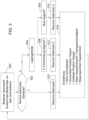
- the Figure 2 shows the electronic control unit 46 and the connected sensors and actuators in detail.
- the electronic control unit 46 comprises a processing unit 86 and a control unit 90.
- a camera 48 is mounted on the front of the roof of the cabin 38 and serves to capture the crop 76 in front of the harvesting machine 10.
- An image processing unit 76 receives the image signals from the camera 74 and sends signals 78 to the processing unit 86.
- the processing unit 86 also receives signals from a position determining device 120, a sensor 122 for detecting the position of the actuator 114, a sensor 80 for detecting the position of the actuator 58, a sensor 82 for detecting the position of the actuator 68, a sensor 84 for detecting the position of the actuator 70, a sensor 104 for detecting the position of the actuator 98 and a sensor 106 for detecting the position of the actuator 102.
- the operator interface 44 is connected via a signal conditioner 96 to the processing unit 86, which is also connected to a memory 124.
- the control unit 90 receives from the signal processing unit 86, on the one hand, signals 88 which contain setpoint values for the working parameters or settings of the actuators 58, 68, 98, 102, 70, 108, 110, 114 and, on the other hand, signals 94 which contain actual values of the working parameters or positions of the actuators 58, 68, 98, 102, 70, 108, 110, 114 and issues corresponding control signals to the actuators 58, 68, 98, 102, 70, 108, 110, 114 (or drivers or valve units or the like connected between the control unit and the actuators 58, 68, 98, 102, 70, 108, 110, 114) in order to transmit the actual values of the working parameters to to adjust the target values.
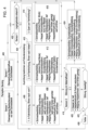
- a first possible mode of operation of the electronic control unit 46 is shown in the Figure 3 shown.
- three data sets are stored in the memory 124 for settings of the actuator 70 for specifying the height of the cutting unit 18 above the ground, the actuator 68 for the position of the reel 52 in the forward direction V, the actuator 58 for the vertical position of the reel 52, the speed of the actuator 110 for specifying the rotational speed of the reel 52 (or the ratio between the reel speed and the forward speed of the harvesting machine 10) and the actuator 114 for the angle of inclination of the reel tines 66.
- the first data set corresponds to normal harvesting operation
- the second data set to stored grain lying in the direction of travel
- the third data set to stored grain lying transversely.
- step 300 the operator monitors the condition of the crop 76 in front of the cutting unit 18. By pressing an associated button on the operator interface 44 (or not pressing a button provided for entering stored grain), he can inform the control unit 46 that there is normal standing grain (step 302). If this is the case, the first data set is called up in step 310 and the actuators 70, 68, 58, 110 and 114 are controlled using the first data set in step 316. If the operator reports via the operator interface 44 that there is stored grain, for which a corresponding button can be pressed, step 304 follows, after which the direction of the stored grain can be entered (steps 306, 308), for which further buttons can be provided on the operator interface 44.
- buttons one of which has a symbol oriented in the forward direction V and one of which has a transverse symbol, e.g. an arrow, the first-mentioned symbol being assigned to step 306 and the second-mentioned symbol to step 308.
- the second data set is called up in step 312 and the actuators 70, 68, 58, 110 and 114 are controlled using the second data set in step 316.
- the third data set is called up in step 314 and the actuators 70, 68, 58, 110 and 114 are controlled using the third data set in step 316. Possible details of these data sets are explained in the discussion of the second embodiment of the procedure of the control unit 46.
- FIG. 4 a second possible procedure of the electronic control unit 46 is shown.
- This automated procedure uses a first sensor to monitor the crop stock 76 in front of the cutting unit 18 and a second sensor to monitor the material flow in the cutting unit 18.
- the camera 48 with the image processing system 74 takes over the tasks of both sensors.
- the first sensor is used to detect any grain that may be lying in front of the cutting unit 18.
- the image processing system 74 therefore uses the image signals from the camera 48 to detect whether and, if so, in which orientation there is stored grain in front of the cutting unit 18.
- this information can have been obtained in advance, e.g. by means of a drone equipped with a camera that has flown over the field, and stored in a map in the memory 124 and read out based on the position and direction of travel of the harvesting machine 10 determined by the position determination device 120.
- the second sensor serves to monitor the material flow in the cutting unit 18, in particular in the receiving area, ie in the area from the cutter bar 50 to the cross conveyor 112.
- the camera 48 can provide suitable images which are evaluated by the image processing system 74.
- EP 2 143 316 A1 and the DE 10 2016 202 628 A1 which are incorporated by reference into these documents.
- step 400 the processing unit 86 therefore receives the signals 78 from the image processing system, which indicate possible stored grain or disturbances in the material flow in the receiving area of the cutting unit 18.
- Step 400 is followed by step 402, in which it is checked whether the first sensor has detected stored grain. If this is not the case, step 418 follows, in which it is checked whether signals from the second sensor (ie the image processing system 74) indicate to the processing unit 86 that there is a disturbance in the material flow in the receiving area of the cutting unit 18 between the knife bar 50 and the cross conveyor 112. If this is not the case, step 424 follows, in which the processing unit 86 retrieves a series of basic settings for the actuators 70, 68, 58, 110 and 114 from the memory 124. These basic settings can have been entered beforehand by the operator or can be preset at the factory.
- the actuators 70, 68, 58, 110 and 114 are therefore operated with sensible working parameters that are well suited to normal conditions (standing crop 76).
- the reel 52 should only slightly assist the intake of the grain. All settings are such that the reel 52 does not loosen any grains from the ears, or that loosened grains cannot fall to the ground in front of the cutting unit.
- the reel tines 66 should be almost vertical or only slightly set back. The reel 52 only dips into the crop 76 shortly before the knife bar 50. The reel 52 is at a height such that the reel tine carriers 64 can only lightly touch the tips of the ears. When the reel tines 66 dip, the relative movement between the reel tines 66 and the ears should be minimal.
- the horizontal component of the reel speed is only slightly higher than the driving speed, so that the cut grain is only slightly pushed into the cutting unit 18.
- the ratio of reel speed to driving speed is determined using systems for reel speed control that are already in common use. This setting of the four parameters can be saved as a "basic setting" and can be quickly accessed at any time by activating an assigned button on the operator interface 44, analogous to step 310 of the Figure 3 .
- step 404 follows, in which the orientation of the stored grain is determined by the image processing system 74 based on the signals from the first sensor, for which reference is again made to the disclosures of US patent application 62/535043 of July 20, 2017 (published as US 2019/0021226 A1 ) and the DE 10 2016 215 197 A1 is referred to.
- step 408 in which the cutting unit height (actuator 70) is brought to a minimum, i.e. the cutting unit 18 is operated with a floating position of the actuator 70.
- the reel 52 is moved as far forward as possible with the actuator 68, so that the lowest point of the path of the reel tines 66 is located far in front of the knife bar 50.
- the reel 52 is brought into a relatively low position with the actuator 68, which is below the basic position according to step 424.
- the inclination of the reel tines 66 is adjusted far to the rear with the actuator 114, i.e.
- the reel tines 66 extend at the lowest point of their path from the reel tine carrier 64 relatively obliquely backwards and downwards, e.g. at an angle of approx. 45° or up to 60°.
- the speed of the reel 52 is increased by the actuator 110, so that the so-called K factor, which is multiplied by the forward speed of the harvesting machine 10 to determine the speed, is much higher than in the basic setting (step 424).
- K factor which is multiplied by the forward speed of the harvesting machine 10 to determine the speed
- the reel tines 66 should reach under the ears well in front of the knife bar 50, lift the crop 76 (grain) so that it can be cut and then lift it into the cutting unit 18.
- the reel tines 66 are therefore positioned far back, up to 60° for very flat grain. They should be able to slide under the lying ears.
- the reel 52 is positioned far forward so that the reel tine supports 64 reach the lowest point of the track well in front of the knife bar 50 and then come back up again.
- the reel 52 is positioned so low that the reel tines 66 can slide under the ears.
- the speed of the reel 52 is increased significantly so that the crop 76 can be sufficiently lifted before cutting. The minimum speed is such that at least the ears are cut off.
- This setting of the four parameters can be used for step 312 of the Figure 3 can also be saved as a customer-specific setting for stored grain lying in the direction of travel and accessed via an assigned button on the operator interface 44.
- step 412 follows, in which the cutting unit height (actuator 70) is reduced to a minimum, ie the Cutting unit 18 is operated with a floating position of the actuator 70.
- the reel 52 is set in its forward direction to the home position (as in step 424) using the actuator 68.
- the reel 52 is moved to a relatively low position, which is below the home position according to step 424, using the actuator 68.
- the inclination of the reel tines 66 is set to the home position (as in step 424) using the actuator 114.
- the speed of the reel 52 is set to the home position (as in step 424) using the actuator 110.
- ear lifters should be able to move easily under the grain 76 and lift it. Since the cutting table literally slides under the grain 76 until it is cut, it usually slides easily into the cutting unit 18 without additional support.
- the reel tines 66 remain vertical. The horizontal position and the speed remain in the basic setting. If the grain lies across the entire cutting width or at least across most of the cutting width, the reel can be lowered to assist the intake. If it lies across only part of the cutting width, the reel remains at the height of the basic setting, or at the height corresponding to the ear horizon in the standing area.
- step 416 follows in which the cutting unit height (actuator 70) is brought to a minimum, ie the cutting unit 18 is operated with a floating position of the actuator 70.
- the reel 52 is moved forwards with the actuator 68 so that the lowest point of the path of the reel tines 66 is located slightly in front of the cutter bar 50.
- the reel 52 is moved to a relatively low position with the actuator 68, which is below the basic position according to step 424.
- the inclination of the reel tines 66 is adjusted backwards using the actuator 114, ie the reel tines 66 extend backwards and downwards from the reel tine carrier 64 at the lowest point of their path, but less steeply than in step 408.
- the speed of the reel 52 is increased by the actuator 110, so that the so-called K factor, which is multiplied by the forward speed of the harvesting machine 10 to determine the speed, is much higher than in the basic setting (step 424).
- K factor which is multiplied by the forward speed of the harvesting machine 10 to determine the speed
- the reel 52 can help to place the grain 76 on the grain lifters.
- the reel parameters are set as in step 408, with the difference that the reel 52 now engages in the grain just before the grain lifters. If no grain lifters are used, then it only engages just before the knife bar 50.
- This setting of the four parameters can be used for step 314 of the Figure 3 can also be saved as a customer-specific setting for stored grain lying in the direction of travel and accessed via an assigned button on the operator interface 44.
- Steps 402, 408, 412 and 416 are followed by step 418 already mentioned above, in which it is queried whether signals from the second sensor (i.e. the image processing system 74) indicate to the processing unit 86 that there is a disturbance in the material flow in the receiving area of the cutting unit 18 between the knife bar 50 and the cross conveyor 112.
- the second sensor i.e. the image processing system 74
- step 424 follows and otherwise step 420 follows, in which the processing unit 86 instructs the actuator 54 via the control unit 90 to slightly raise the reel 52 (compared to the position after step 408, 410 or 412) or (directly starting from step 402) to lower it compared to the normal position and optionally reduces the speed of the reel 52 by the actuator 110 so that the so-called K factor, which is multiplied by the forward speed of the harvesting machine 10 to determine the speed, is lower than in the basic setting (step 424).
- the reel tines 66 can also be set tilted backwards in order to allow them to engage the jammed material more aggressively. The reel 52 is therefore in a relatively low position until the reel tines 6 briefly brush over the knife bar 50 or over the cutting table. In stubborn cases, the reel speed is also increased.
- step 422 it is checked whether the fault has been eliminated. If this is the case, step 424 follows and otherwise step 426.
- the intervention according to step 420 preferably only takes place for a short time, on the one hand to give the sensor a clear view of the fault and to check the success of the action and on the other hand to reduce the risk that the reel 52 throws over cut grain or even starts to wind itself.
- the sensor should also be able to detect these two cases and at the latest then interrupt an intervention to remove the blockage. The same applies to cases of stored grain, especially if the grain is only lying over a partial width of the cutting unit 18, but is standing in other places.
- the procedure according to step 420 can optionally be repeated one or more times. Only then, if the procedure fails, is a warning issued (step 426) so that the operator can intervene himself.
- the flow charts according to Figure 3 or 4 The actuator settings generated can be overridden in a conventional manner by operator inputs via the operator interface 44 and thus improved if necessary. In addition, they can be fine-tuned by automatic control circuits with closed or open loops.
Landscapes
- Life Sciences & Earth Sciences (AREA)
- Environmental Sciences (AREA)
- Outside Dividers And Delivering Mechanisms For Harvesters (AREA)
- Harvester Elements (AREA)
Claims (2)
- Moissonneuse (10) comprenant un mécanisme de coupe (18) qui est équipé d'une barre de coupe (50) pour couper la récolte (76) sur un champ, un rabatteur (52) disposé au-dessus de la barre de coupe (50) et muni de dents de rabatteur (66) et un convoyeur transversal (112) pour évacuer la récolte coupée jusqu'à une ouverture de distribution,dans laquelle le rabatteur (52) comprend des bras de rabatteur (116) pouvant être mis en mouvement autour d'un axe de rotation, des supports de dents de rabatteur (64) en appui rotatif autour de leurs axes longitudinaux sur les bras de rabatteur (116) avec des dents de rabatteur (66) rattachées à ceux-ci, et un actionneur (114) actionné par une force extérieure et relié à une unité de commande électronique (46) pour ajuster l'angle de rotation des supports de dents de rabatteur (64) par rapport aux bras de rabatteur (116),et l'unité de commande électronique (46) peut fonctionner pour ajuster l'actionneur (114) en fonction d'au moins une propriété de la récolte à récolter,caractérisée en ce que l'unité de commande électronique (46) est reliée à un capteur pour identifier des céréales couchées se trouvant devant le mécanisme de coupe et l'orientation de celles-ci, et/ou à une carte sauvegardée dans laquelle sont sauvegardées des positions de céréales couchées se trouvant devant le mécanisme de coupe (18) et l'orientation de celles-ci, et qui peut fonctionner pour piloter l'actionneur (114) en fonction de la carte et/ou des signaux du capteur en fonction de la présence et de l'orientation de céréales couchées à ramasser,et/ou en ce que l'unité de commande électronique (46) est reliée à un capteur pour identifier des irrégularités dans le comportement de convoyage de la récolte dans la zone de réception du mécanisme de coupe (18) entre la barre de coupe (50) et le convoyeur transversal (112), et peut fonctionner pour piloter l'actionneur (114) en fonction des signaux du capteur.
- Moissonneuse (10), selon la revendication 1, dans laquelle l'unité de commande (46) peut fonctionner pour piloter des actionneurs supplémentaires (70, 68, 58, 110) pour ajuster la hauteur du mécanisme de coupe et/ou la position du rabatteur (52) dans la direction avant et/ou la position du rabatteur (52) dans la direction verticale et/ou la vitesse de la rotation du rabatteur (52) sur la base d'au moins un capteur et/ou de données inscrites sur la carte.
Applications Claiming Priority (1)
| Application Number | Priority Date | Filing Date | Title |
|---|---|---|---|
| DE102018206507.1A DE102018206507A1 (de) | 2018-04-26 | 2018-04-26 | Schneidwerk mit selbsttätiger Einstellung der Haspelzinkenorientierung |
Publications (2)
| Publication Number | Publication Date |
|---|---|
| EP3560314A1 EP3560314A1 (fr) | 2019-10-30 |
| EP3560314B1 true EP3560314B1 (fr) | 2024-10-30 |
Family
ID=66217804
Family Applications (1)
| Application Number | Title | Priority Date | Filing Date |
|---|---|---|---|
| EP19169583.2A Active EP3560314B1 (fr) | 2018-04-26 | 2019-04-16 | Mécanisme de coupe à réglage automatique de l'orientation de dent de rabatteur |
Country Status (3)
| Country | Link |
|---|---|
| US (1) | US11044847B2 (fr) |
| EP (1) | EP3560314B1 (fr) |
| DE (1) | DE102018206507A1 (fr) |
Families Citing this family (73)
| Publication number | Priority date | Publication date | Assignee | Title |
|---|---|---|---|---|
| BR112020005109A2 (pt) * | 2017-09-15 | 2020-09-24 | Cnh Industrial America Llc | conjunto de ajuste de estrutura de came para um molinete de colheita |
| US10827676B2 (en) | 2018-01-29 | 2020-11-10 | Deere & Company | Monitor and control system for a harvester |
| US11744180B2 (en) * | 2018-01-29 | 2023-09-05 | Deere & Company | Harvester crop mapping |
| DE102019214486B4 (de) | 2018-09-27 | 2023-07-27 | Deere & Company | Erntevorsatzüberwachung anhand von Erntemengenabweichungen |
| US11079725B2 (en) | 2019-04-10 | 2021-08-03 | Deere & Company | Machine control using real-time model |
| US11178818B2 (en) | 2018-10-26 | 2021-11-23 | Deere & Company | Harvesting machine control system with fill level processing based on yield data |
| US11641800B2 (en) | 2020-02-06 | 2023-05-09 | Deere & Company | Agricultural harvesting machine with pre-emergence weed detection and mitigation system |
| US11653588B2 (en) | 2018-10-26 | 2023-05-23 | Deere & Company | Yield map generation and control system |
| US11240961B2 (en) | 2018-10-26 | 2022-02-08 | Deere & Company | Controlling a harvesting machine based on a geo-spatial representation indicating where the harvesting machine is likely to reach capacity |
| US11589509B2 (en) | 2018-10-26 | 2023-02-28 | Deere & Company | Predictive machine characteristic map generation and control system |
| US11672203B2 (en) | 2018-10-26 | 2023-06-13 | Deere & Company | Predictive map generation and control |
| US11957072B2 (en) | 2020-02-06 | 2024-04-16 | Deere & Company | Pre-emergence weed detection and mitigation system |
| US12069978B2 (en) | 2018-10-26 | 2024-08-27 | Deere & Company | Predictive environmental characteristic map generation and control system |
| US11467605B2 (en) | 2019-04-10 | 2022-10-11 | Deere & Company | Zonal machine control |
| DE102018220337A1 (de) | 2018-11-27 | 2020-05-28 | Deere & Company | Erntevorsatz mit verstellbarer Querförderschnecke |
| US11234366B2 (en) | 2019-04-10 | 2022-02-01 | Deere & Company | Image selection for machine control |
| US11778945B2 (en) | 2019-04-10 | 2023-10-10 | Deere & Company | Machine control using real-time model |
| US11793111B2 (en) | 2019-11-27 | 2023-10-24 | Cnh Industrial America Llc | Harvesting head reel-mounted laser measurement |
| US12225846B2 (en) | 2020-02-06 | 2025-02-18 | Deere & Company | Machine control using a predictive map |
| US12329148B2 (en) | 2020-02-06 | 2025-06-17 | Deere & Company | Predictive weed map and material application machine control |
| US12035648B2 (en) | 2020-02-06 | 2024-07-16 | Deere & Company | Predictive weed map generation and control system |
| US11477940B2 (en) | 2020-03-26 | 2022-10-25 | Deere & Company | Mobile work machine control based on zone parameter modification |
| BR112022023976A2 (pt) * | 2020-05-29 | 2022-12-20 | Cnh Ind America Llc | Controle de altura de coletor para colheitadeira |
| US11711995B2 (en) | 2020-10-09 | 2023-08-01 | Deere & Company | Machine control using a predictive map |
| US12069986B2 (en) | 2020-10-09 | 2024-08-27 | Deere & Company | Map generation and control system |
| US11845449B2 (en) | 2020-10-09 | 2023-12-19 | Deere & Company | Map generation and control system |
| US12386354B2 (en) | 2020-10-09 | 2025-08-12 | Deere & Company | Predictive power map generation and control system |
| US11844311B2 (en) | 2020-10-09 | 2023-12-19 | Deere & Company | Machine control using a predictive map |
| US11874669B2 (en) | 2020-10-09 | 2024-01-16 | Deere & Company | Map generation and control system |
| US11635765B2 (en) | 2020-10-09 | 2023-04-25 | Deere & Company | Crop state map generation and control system |
| US11592822B2 (en) | 2020-10-09 | 2023-02-28 | Deere & Company | Machine control using a predictive map |
| US11727680B2 (en) | 2020-10-09 | 2023-08-15 | Deere & Company | Predictive map generation based on seeding characteristics and control |
| US11675354B2 (en) | 2020-10-09 | 2023-06-13 | Deere & Company | Machine control using a predictive map |
| US20220110258A1 (en) | 2020-10-09 | 2022-04-14 | Deere & Company | Map generation and control system |
| US11895948B2 (en) | 2020-10-09 | 2024-02-13 | Deere & Company | Predictive map generation and control based on soil properties |
| US11927459B2 (en) | 2020-10-09 | 2024-03-12 | Deere & Company | Machine control using a predictive map |
| US11474523B2 (en) | 2020-10-09 | 2022-10-18 | Deere & Company | Machine control using a predictive speed map |
| US20220110238A1 (en) | 2020-10-09 | 2022-04-14 | Deere & Company | Machine control using a predictive map |
| US11983009B2 (en) | 2020-10-09 | 2024-05-14 | Deere & Company | Map generation and control system |
| US11849672B2 (en) | 2020-10-09 | 2023-12-26 | Deere & Company | Machine control using a predictive map |
| US11946747B2 (en) | 2020-10-09 | 2024-04-02 | Deere & Company | Crop constituent map generation and control system |
| US12178158B2 (en) | 2020-10-09 | 2024-12-31 | Deere & Company | Predictive map generation and control system for an agricultural work machine |
| US11871697B2 (en) | 2020-10-09 | 2024-01-16 | Deere & Company | Crop moisture map generation and control system |
| US11825768B2 (en) | 2020-10-09 | 2023-11-28 | Deere & Company | Machine control using a predictive map |
| US11864483B2 (en) | 2020-10-09 | 2024-01-09 | Deere & Company | Predictive map generation and control system |
| US11849671B2 (en) | 2020-10-09 | 2023-12-26 | Deere & Company | Crop state map generation and control system |
| US12422847B2 (en) | 2020-10-09 | 2025-09-23 | Deere & Company | Predictive agricultural model and map generation |
| US12550802B2 (en) | 2020-10-08 | 2026-02-17 | Deere & Company | Predictive machine characteristic map generation and control system |
| US11650587B2 (en) | 2020-10-09 | 2023-05-16 | Deere & Company | Predictive power map generation and control system |
| US12419220B2 (en) | 2020-10-09 | 2025-09-23 | Deere & Company | Predictive map generation and control system |
| US12013245B2 (en) | 2020-10-09 | 2024-06-18 | Deere & Company | Predictive map generation and control system |
| US11889788B2 (en) | 2020-10-09 | 2024-02-06 | Deere & Company | Predictive biomass map generation and control |
| US12250905B2 (en) | 2020-10-09 | 2025-03-18 | Deere & Company | Machine control using a predictive map |
| US11889787B2 (en) | 2020-10-09 | 2024-02-06 | Deere & Company | Predictive speed map generation and control system |
| US20220117158A1 (en) * | 2020-10-15 | 2022-04-21 | Topcon Positioning Systems, Inc. | Method and apparatus for determining and mapping crop height |
| US12127500B2 (en) | 2021-01-27 | 2024-10-29 | Deere & Company | Machine control using a map with regime zones |
| US12108704B2 (en) * | 2021-05-19 | 2024-10-08 | Deere & Company | Agricultural header reel position control based on header wing position |
| US12433197B2 (en) | 2021-09-03 | 2025-10-07 | Deere & Company | Harvesting machine cutter head with automated posture-based reel finger pitch adjustment |
| US12229886B2 (en) | 2021-10-01 | 2025-02-18 | Deere & Company | Historical crop state model, predictive crop state map generation and control system |
| US12310286B2 (en) | 2021-12-14 | 2025-05-27 | Deere & Company | Crop constituent sensing |
| US12302791B2 (en) | 2021-12-20 | 2025-05-20 | Deere & Company | Crop constituents, predictive mapping, and agricultural harvester control |
| US12245549B2 (en) | 2022-01-11 | 2025-03-11 | Deere & Company | Predictive response map generation and control system |
| US12520759B2 (en) | 2022-01-26 | 2026-01-13 | Deere & Company | Systems and methods for predicting material dynamics |
| US12082531B2 (en) | 2022-01-26 | 2024-09-10 | Deere & Company | Systems and methods for predicting material dynamics |
| US12550821B2 (en) | 2022-03-15 | 2026-02-17 | Deere & Company | Systems and methods for predictive reel control |
| DE102022107016A1 (de) * | 2022-03-24 | 2023-09-28 | Claas Selbstfahrende Erntemaschinen Gmbh | Landwirtschaftliche Erntemaschine sowie Verfahren zur Steuerung einer landwirtschaftlichen Erntemaschine |
| US12295288B2 (en) | 2022-04-05 | 2025-05-13 | Deere &Company | Predictive machine setting map generation and control system |
| US12358493B2 (en) | 2022-04-08 | 2025-07-15 | Deere & Company | Systems and methods for predictive power requirements and control |
| US12058951B2 (en) | 2022-04-08 | 2024-08-13 | Deere & Company | Predictive nutrient map and control |
| US12582035B2 (en) | 2022-04-08 | 2026-03-24 | Deere & Company | Systems and methods for predictive power requirements and control |
| US12284934B2 (en) | 2022-04-08 | 2025-04-29 | Deere & Company | Systems and methods for predictive tractive characteristics and control |
| US12298767B2 (en) | 2022-04-08 | 2025-05-13 | Deere & Company | Predictive material consumption map and control |
| US12426542B2 (en) | 2022-08-19 | 2025-09-30 | Cnh Industrial America Llc | Harvester reel having adjustable tine bars and method for resetting same |
Family Cites Families (24)
| Publication number | Priority date | Publication date | Assignee | Title |
|---|---|---|---|---|
| DE1047516B (de) | 1953-09-12 | 1958-12-24 | Dechentreiter Maschinenfabrik | Haspel zum Zufuehren des Erntegutes zum Schneidwerk, vorzugsweise an Maehdreschmaschinen |
| DE2411153A1 (de) | 1974-03-08 | 1975-09-25 | Fahr Ag Maschf | Einrichtung zum messen von einflussgroessen fuer die regelung der arbeitsorgane von erntemaschinen, insbesondere maehdrescher |
| DE19623754A1 (de) * | 1996-06-14 | 1997-12-18 | Claas Ohg | Erntemaschine mit einem in seiner Arbeitslage gegenüber dem Boden höhenverstellbaren Vorsatzbearbeitungsgerät |
| CA2180625C (fr) * | 1996-07-05 | 2003-09-30 | Francois Talbot | Dispositif de reglage de l'angle des doigts de l'organe de ramassage d'une moissonneuse |
| US6170244B1 (en) | 1999-04-28 | 2001-01-09 | Deere & Company | Cam path for orientating fingers of a harvesting reel |
| US6442918B1 (en) * | 2000-09-27 | 2002-09-03 | Macdon Industries Ltd. | Adjustment of a pickup reel of a crop harvesting header |
| US6591598B2 (en) | 2001-10-01 | 2003-07-15 | Macdon Industries Ltd. | Crop harvesting header with cam controlled movement of the reel fingers |
| UA76007C2 (en) | 2001-12-11 | 2006-06-15 | Reaper for a combine harvester | |
| DE102008032191A1 (de) | 2008-07-09 | 2010-01-14 | Claas Selbstfahrende Erntemaschinen Gmbh | Selbstfahrende Erntemaschine |
| DE102011017621A1 (de) | 2011-04-27 | 2012-10-31 | Deere & Company | Anordnung und Verfahren zur Erfassung der Menge von Pflanzen auf einem Feld |
| DE102011085380A1 (de) * | 2011-10-28 | 2013-05-02 | Deere & Company | Anordnung und Verfahren zur vorausschauenden Untersuchung von mit einer Erntemaschine aufzunehmenden Pflanzen |
| US8800256B2 (en) | 2011-12-23 | 2014-08-12 | Agco Corporation | Tine adjustment for a header |
| US20130160418A1 (en) * | 2011-12-23 | 2013-06-27 | Agco Corporation | Support for Reel or Auger with Single Piece Tube |
| US9763385B2 (en) * | 2012-08-08 | 2017-09-19 | Cnh Industrial America Llc | Automatic control of relative positioning of the cutter bar and reel |
| DE102013208957A1 (de) | 2013-05-15 | 2014-11-20 | Deere & Company | Schneidwerk mit einem längenverstellbaren Schneidtisch |
| CA2876686C (fr) * | 2014-12-24 | 2021-01-19 | Honey Bee Manufacturing Ltd. | Systeme de moulinet |
| WO2016101059A1 (fr) | 2014-12-24 | 2016-06-30 | Honey Bee Manufacturing Ltd. | Système de rabatteur |
| US9696162B2 (en) | 2015-09-17 | 2017-07-04 | Deere & Company | Mission and path planning using images of crop wind damage |
| DE102016202628B4 (de) | 2016-02-19 | 2025-02-06 | Deere & Company | Sensoranordnung zur Funktionsüberwachung eines Erntevorsatzes |
| DE102016118637A1 (de) | 2016-09-30 | 2018-04-05 | Claas Selbstfahrende Erntemaschinen Gmbh | Mähdrescher mit einem Schneidwerk und Steuerung eines Schneidwerks |
| US10238033B2 (en) * | 2017-02-27 | 2019-03-26 | Cnh Industrial America Llc | Reel finger assembly for a harvesting reel |
| US10182525B2 (en) * | 2017-05-17 | 2019-01-22 | Cnh Industrial America Llc | Feeder and header positioning method |
| HUE065826T2 (hu) * | 2017-09-05 | 2024-06-28 | Macdon Ind Ltd | Termény-betakarító vágóasztal motollamozgásra érzékeny bütyökbeállító alkotórésszel |
| US10426091B2 (en) * | 2018-11-20 | 2019-10-01 | Honey Bee Manufacturing Ltd. | Pickup reel for a crop harvesting header |
-
2018
- 2018-04-26 DE DE102018206507.1A patent/DE102018206507A1/de not_active Withdrawn
-
2019
- 2019-04-16 EP EP19169583.2A patent/EP3560314B1/fr active Active
- 2019-04-25 US US16/394,933 patent/US11044847B2/en active Active
Also Published As
| Publication number | Publication date |
|---|---|
| US20190327892A1 (en) | 2019-10-31 |
| US11044847B2 (en) | 2021-06-29 |
| DE102018206507A1 (de) | 2019-10-31 |
| EP3560314A1 (fr) | 2019-10-30 |
Similar Documents
| Publication | Publication Date | Title |
|---|---|---|
| EP3560314B1 (fr) | Mécanisme de coupe à réglage automatique de l'orientation de dent de rabatteur | |
| EP3403485B1 (fr) | Dispositif d'auto-apprentissage, prenant en considération les entrées de correction destiné au contrôle automatique d'un paramètre de travail d'un dispositif de transport de produit de la récolte et/ou de traitement | |
| EP3662741B2 (fr) | Machine de travail agricole ainsi que procédé de fonctionnement d'une machine de travail agricole | |
| EP3603379B1 (fr) | Dispositif de commande automatique de l'entraînement d'un élément appliqué latéralement à une tête de récolte, lequel sert à distribuer le produit de la récolte à la frontière entre la culture à préserver et à récolter | |
| EP2143316B1 (fr) | Moissonneuse automobile | |
| EP3300580B2 (fr) | Moissonneuse-batteuse pourvue de barre de coupe et dispositif de commande d'une barre de coupe | |
| DE102016202628B4 (de) | Sensoranordnung zur Funktionsüberwachung eines Erntevorsatzes | |
| EP3494771B2 (fr) | Dispositif de hauteur de coupe automatique | |
| EP3335541B1 (fr) | Procédé de fonctionnement d'une barre de coupe | |
| EP3659421B1 (fr) | Tête de récolte dotée de vis sans fin transversale réglable | |
| EP2591664A1 (fr) | Crible pour une installation de nettoyage d'une moissonneuse-batteuse | |
| EP3597027B1 (fr) | Moissonneuse-batteuse doté d'un convoyeur incliné pourvu de rouleau de déviation inférieur réglable | |
| DE102023127392A1 (de) | System und Verfahren zur automatischen Einstellung von Deckplatten | |
| DE102008001779B4 (de) | Erntevorsatz mit einem Gutaufnehmer und einer Querförderschnecke | |
| EP4252519B1 (fr) | Moissonneuse agricole et procédé de commande d'une moissonneuse agricole | |
| DE102011084288A1 (de) | Selbstfahrende Erntemaschine mit pendelnd aufgehängter Lenkachse und pendelwinkelabhängiger Lenkwinkelbegrenzung | |
| DE10359398B3 (de) | Erntegutbergungseinrichtung mit Abstreifelementen | |
| EP4531538A1 (fr) | Accessoire de ramassage pour machine de récolte | |
| EP4154700A1 (fr) | Engin d'abattage-façonnage pourvu de mécanisme de coupe de bande | |
| EP4154697A1 (fr) | Système d'aide à la conduite d'un engin d'abattage-façonnage pourvu de mécanisme de coupe de bande | |
| DE102022119175A1 (de) | Schneidwerk für eine erntemaschine mit automatischer haspelfingerneigungseinstellung auf positionsbasis | |
| WO2024217638A1 (fr) | Accessoire de ramassage pour machine de récolte | |
| EP4464147A1 (fr) | Tête de récolte pour moissonneuse-batteuse destinée à la récolte de cultures comprenant des grains en croissance sur tiges | |
| EP4709141A1 (fr) | Accessoire de ramassage pour une machine de récolte | |
| DE102024116067A1 (de) | Lieschkolben-Größenerkennung |
Legal Events
| Date | Code | Title | Description |
|---|---|---|---|
| PUAI | Public reference made under article 153(3) epc to a published international application that has entered the european phase |
Free format text: ORIGINAL CODE: 0009012 |
|
| STAA | Information on the status of an ep patent application or granted ep patent |
Free format text: STATUS: THE APPLICATION HAS BEEN PUBLISHED |
|
| AK | Designated contracting states |
Kind code of ref document: A1 Designated state(s): AL AT BE BG CH CY CZ DE DK EE ES FI FR GB GR HR HU IE IS IT LI LT LU LV MC MK MT NL NO PL PT RO RS SE SI SK SM TR |
|
| AX | Request for extension of the european patent |
Extension state: BA ME |
|
| STAA | Information on the status of an ep patent application or granted ep patent |
Free format text: STATUS: REQUEST FOR EXAMINATION WAS MADE |
|
| 17P | Request for examination filed |
Effective date: 20200430 |
|
| RBV | Designated contracting states (corrected) |
Designated state(s): AL AT BE BG CH CY CZ DE DK EE ES FI FR GB GR HR HU IE IS IT LI LT LU LV MC MK MT NL NO PL PT RO RS SE SI SK SM TR |
|
| STAA | Information on the status of an ep patent application or granted ep patent |
Free format text: STATUS: EXAMINATION IS IN PROGRESS |
|
| 17Q | First examination report despatched |
Effective date: 20220603 |
|
| GRAP | Despatch of communication of intention to grant a patent |
Free format text: ORIGINAL CODE: EPIDOSNIGR1 |
|
| STAA | Information on the status of an ep patent application or granted ep patent |
Free format text: STATUS: GRANT OF PATENT IS INTENDED |
|
| INTG | Intention to grant announced |
Effective date: 20240715 |
|
| GRAS | Grant fee paid |
Free format text: ORIGINAL CODE: EPIDOSNIGR3 |
|
| GRAA | (expected) grant |
Free format text: ORIGINAL CODE: 0009210 |
|
| STAA | Information on the status of an ep patent application or granted ep patent |
Free format text: STATUS: THE PATENT HAS BEEN GRANTED |
|
| AK | Designated contracting states |
Kind code of ref document: B1 Designated state(s): AL AT BE BG CH CY CZ DE DK EE ES FI FR GB GR HR HU IE IS IT LI LT LU LV MC MK MT NL NO PL PT RO RS SE SI SK SM TR |
|
| REG | Reference to a national code |
Ref country code: GB Ref legal event code: FG4D Free format text: NOT ENGLISH |
|
| REG | Reference to a national code |
Ref country code: CH Ref legal event code: EP |
|
| REG | Reference to a national code |
Ref country code: DE Ref legal event code: R096 Ref document number: 502019012373 Country of ref document: DE |
|
| REG | Reference to a national code |
Ref country code: IE Ref legal event code: FG4D Free format text: LANGUAGE OF EP DOCUMENT: GERMAN |
|
| REG | Reference to a national code |
Ref country code: LT Ref legal event code: MG9D |
|
| REG | Reference to a national code |
Ref country code: NL Ref legal event code: MP Effective date: 20241030 |
|
| PG25 | Lapsed in a contracting state [announced via postgrant information from national office to epo] |
Ref country code: PT Free format text: LAPSE BECAUSE OF FAILURE TO SUBMIT A TRANSLATION OF THE DESCRIPTION OR TO PAY THE FEE WITHIN THE PRESCRIBED TIME-LIMIT Effective date: 20250228 Ref country code: IS Free format text: LAPSE BECAUSE OF FAILURE TO SUBMIT A TRANSLATION OF THE DESCRIPTION OR TO PAY THE FEE WITHIN THE PRESCRIBED TIME-LIMIT Effective date: 20250228 Ref country code: HR Free format text: LAPSE BECAUSE OF FAILURE TO SUBMIT A TRANSLATION OF THE DESCRIPTION OR TO PAY THE FEE WITHIN THE PRESCRIBED TIME-LIMIT Effective date: 20241030 |
|
| PG25 | Lapsed in a contracting state [announced via postgrant information from national office to epo] |
Ref country code: FI Free format text: LAPSE BECAUSE OF FAILURE TO SUBMIT A TRANSLATION OF THE DESCRIPTION OR TO PAY THE FEE WITHIN THE PRESCRIBED TIME-LIMIT Effective date: 20241030 Ref country code: NL Free format text: LAPSE BECAUSE OF FAILURE TO SUBMIT A TRANSLATION OF THE DESCRIPTION OR TO PAY THE FEE WITHIN THE PRESCRIBED TIME-LIMIT Effective date: 20241030 |
|
| PG25 | Lapsed in a contracting state [announced via postgrant information from national office to epo] |
Ref country code: BG Free format text: LAPSE BECAUSE OF FAILURE TO SUBMIT A TRANSLATION OF THE DESCRIPTION OR TO PAY THE FEE WITHIN THE PRESCRIBED TIME-LIMIT Effective date: 20241030 |
|
| PG25 | Lapsed in a contracting state [announced via postgrant information from national office to epo] |
Ref country code: ES Free format text: LAPSE BECAUSE OF FAILURE TO SUBMIT A TRANSLATION OF THE DESCRIPTION OR TO PAY THE FEE WITHIN THE PRESCRIBED TIME-LIMIT Effective date: 20241030 |
|
| PG25 | Lapsed in a contracting state [announced via postgrant information from national office to epo] |
Ref country code: NO Free format text: LAPSE BECAUSE OF FAILURE TO SUBMIT A TRANSLATION OF THE DESCRIPTION OR TO PAY THE FEE WITHIN THE PRESCRIBED TIME-LIMIT Effective date: 20250130 |
|
| PG25 | Lapsed in a contracting state [announced via postgrant information from national office to epo] |
Ref country code: LV Free format text: LAPSE BECAUSE OF FAILURE TO SUBMIT A TRANSLATION OF THE DESCRIPTION OR TO PAY THE FEE WITHIN THE PRESCRIBED TIME-LIMIT Effective date: 20241030 Ref country code: GR Free format text: LAPSE BECAUSE OF FAILURE TO SUBMIT A TRANSLATION OF THE DESCRIPTION OR TO PAY THE FEE WITHIN THE PRESCRIBED TIME-LIMIT Effective date: 20250131 |
|
| PG25 | Lapsed in a contracting state [announced via postgrant information from national office to epo] |
Ref country code: PL Free format text: LAPSE BECAUSE OF FAILURE TO SUBMIT A TRANSLATION OF THE DESCRIPTION OR TO PAY THE FEE WITHIN THE PRESCRIBED TIME-LIMIT Effective date: 20241030 |
|
| PG25 | Lapsed in a contracting state [announced via postgrant information from national office to epo] |
Ref country code: RS Free format text: LAPSE BECAUSE OF FAILURE TO SUBMIT A TRANSLATION OF THE DESCRIPTION OR TO PAY THE FEE WITHIN THE PRESCRIBED TIME-LIMIT Effective date: 20250130 |
|
| PG25 | Lapsed in a contracting state [announced via postgrant information from national office to epo] |
Ref country code: SM Free format text: LAPSE BECAUSE OF FAILURE TO SUBMIT A TRANSLATION OF THE DESCRIPTION OR TO PAY THE FEE WITHIN THE PRESCRIBED TIME-LIMIT Effective date: 20241030 |
|
| PGFP | Annual fee paid to national office [announced via postgrant information from national office to epo] |
Ref country code: DE Payment date: 20250319 Year of fee payment: 7 |
|
| PG25 | Lapsed in a contracting state [announced via postgrant information from national office to epo] |
Ref country code: DK Free format text: LAPSE BECAUSE OF FAILURE TO SUBMIT A TRANSLATION OF THE DESCRIPTION OR TO PAY THE FEE WITHIN THE PRESCRIBED TIME-LIMIT Effective date: 20241030 |
|
| PGFP | Annual fee paid to national office [announced via postgrant information from national office to epo] |
Ref country code: GB Payment date: 20250428 Year of fee payment: 7 |
|
| PGFP | Annual fee paid to national office [announced via postgrant information from national office to epo] |
Ref country code: BE Payment date: 20250428 Year of fee payment: 7 Ref country code: IT Payment date: 20250422 Year of fee payment: 7 |
|
| PG25 | Lapsed in a contracting state [announced via postgrant information from national office to epo] |
Ref country code: EE Free format text: LAPSE BECAUSE OF FAILURE TO SUBMIT A TRANSLATION OF THE DESCRIPTION OR TO PAY THE FEE WITHIN THE PRESCRIBED TIME-LIMIT Effective date: 20241030 |
|
| PGFP | Annual fee paid to national office [announced via postgrant information from national office to epo] |
Ref country code: FR Payment date: 20250425 Year of fee payment: 7 |
|
| PG25 | Lapsed in a contracting state [announced via postgrant information from national office to epo] |
Ref country code: RO Free format text: LAPSE BECAUSE OF FAILURE TO SUBMIT A TRANSLATION OF THE DESCRIPTION OR TO PAY THE FEE WITHIN THE PRESCRIBED TIME-LIMIT Effective date: 20241030 |
|
| PG25 | Lapsed in a contracting state [announced via postgrant information from national office to epo] |
Ref country code: SK Free format text: LAPSE BECAUSE OF FAILURE TO SUBMIT A TRANSLATION OF THE DESCRIPTION OR TO PAY THE FEE WITHIN THE PRESCRIBED TIME-LIMIT Effective date: 20241030 |
|
| PG25 | Lapsed in a contracting state [announced via postgrant information from national office to epo] |
Ref country code: CZ Free format text: LAPSE BECAUSE OF FAILURE TO SUBMIT A TRANSLATION OF THE DESCRIPTION OR TO PAY THE FEE WITHIN THE PRESCRIBED TIME-LIMIT Effective date: 20241030 |
|
| REG | Reference to a national code |
Ref country code: DE Ref legal event code: R097 Ref document number: 502019012373 Country of ref document: DE |
|
| PLBE | No opposition filed within time limit |
Free format text: ORIGINAL CODE: 0009261 |
|
| STAA | Information on the status of an ep patent application or granted ep patent |
Free format text: STATUS: NO OPPOSITION FILED WITHIN TIME LIMIT |
|
| PG25 | Lapsed in a contracting state [announced via postgrant information from national office to epo] |
Ref country code: SE Free format text: LAPSE BECAUSE OF FAILURE TO SUBMIT A TRANSLATION OF THE DESCRIPTION OR TO PAY THE FEE WITHIN THE PRESCRIBED TIME-LIMIT Effective date: 20241030 |
|
| 26N | No opposition filed |
Effective date: 20250731 |
|
| REG | Reference to a national code |
Ref country code: CH Ref legal event code: H13 Free format text: ST27 STATUS EVENT CODE: U-0-0-H10-H13 (AS PROVIDED BY THE NATIONAL OFFICE) Effective date: 20251125 |
|
| PG25 | Lapsed in a contracting state [announced via postgrant information from national office to epo] |
Ref country code: LU Free format text: LAPSE BECAUSE OF NON-PAYMENT OF DUE FEES Effective date: 20250416 |
|
| PG25 | Lapsed in a contracting state [announced via postgrant information from national office to epo] |
Ref country code: MC Free format text: LAPSE BECAUSE OF FAILURE TO SUBMIT A TRANSLATION OF THE DESCRIPTION OR TO PAY THE FEE WITHIN THE PRESCRIBED TIME-LIMIT Effective date: 20241030 |
|
| PG25 | Lapsed in a contracting state [announced via postgrant information from national office to epo] |
Ref country code: CH Free format text: LAPSE BECAUSE OF NON-PAYMENT OF DUE FEES Effective date: 20250430 |
|
| PG25 | Lapsed in a contracting state [announced via postgrant information from national office to epo] |
Ref country code: IE Free format text: LAPSE BECAUSE OF NON-PAYMENT OF DUE FEES Effective date: 20250416 |