EP1491173A9 - Fahrzeuglift für Lasten, insbesondere für Rollstühle - Google Patents
Fahrzeuglift für Lasten, insbesondere für Rollstühle Download PDFInfo
- Publication number
- EP1491173A9 EP1491173A9 EP04102659A EP04102659A EP1491173A9 EP 1491173 A9 EP1491173 A9 EP 1491173A9 EP 04102659 A EP04102659 A EP 04102659A EP 04102659 A EP04102659 A EP 04102659A EP 1491173 A9 EP1491173 A9 EP 1491173A9
- Authority
- EP
- European Patent Office
- Prior art keywords
- platform
- part platform
- vehicle lift
- lift according
- slot
- Prior art date
- Legal status (The legal status is an assumption and is not a legal conclusion. Google has not performed a legal analysis and makes no representation as to the accuracy of the status listed.)
- Granted
Links
- 230000005484 gravity Effects 0.000 claims description 3
- 238000010276 construction Methods 0.000 claims 2
- 239000002184 metal Substances 0.000 description 8
- 238000006073 displacement reaction Methods 0.000 description 3
- 230000000694 effects Effects 0.000 description 3
- 239000004575 stone Substances 0.000 description 2
- 230000007704 transition Effects 0.000 description 2
- 229910000831 Steel Inorganic materials 0.000 description 1
- 238000013459 approach Methods 0.000 description 1
- 238000004091 panning Methods 0.000 description 1
- 239000010959 steel Substances 0.000 description 1
- 230000001960 triggered effect Effects 0.000 description 1
Images


Classifications
-
- A—HUMAN NECESSITIES
- A61—MEDICAL OR VETERINARY SCIENCE; HYGIENE
- A61G—TRANSPORT, PERSONAL CONVEYANCES, OR ACCOMMODATION SPECIALLY ADAPTED FOR PATIENTS OR DISABLED PERSONS; OPERATING TABLES OR CHAIRS; CHAIRS FOR DENTISTRY; FUNERAL DEVICES
- A61G3/00—Ambulance aspects of vehicles; Vehicles with special provisions for transporting patients or disabled persons, or their personal conveyances, e.g. for facilitating access of, or for loading, wheelchairs
- A61G3/02—Loading or unloading personal conveyances; Facilitating access of patients or disabled persons to, or exit from, vehicles
- A61G3/06—Transfer using ramps, lifts or the like
- A61G3/062—Transfer using ramps, lifts or the like using lifts connected to the vehicle
Definitions
- the invention relates to a vehicle lift for loads, in particular for Wheelchairs, with a first part platform and at least a second part Part platform, of which the first part platform around a horizontal Pivot axis movable on a carrier by means of a carrier containing ParallelogrammgestShes connectable to the motor vehicle is and from a rest position, in which the sub-platforms one in the Substantially vertical position, by a pivoting movement about the pivot axis in a first working position can be brought, in which the Part platforms form an overall platform and out of the Total platform by shifting parallel to yourself in at least another job and can be brought back.
- Lifts mounted on vehicles have long been known. They serve to do so, objects or people from inside the vehicle to transport outside and back, if between the level of Vehicle interior and the location to which the objects or Persons are to be brought, a difference in height exists or one Gap must be bridged. An important application find such Lifts in vehicles where wheelchair users are transported.
- Known lifts have a platform that by a lever system is moved. There can be three main positions for such lifts be differentiated. The first position is the rest position while the the lift is not used. The platform is then in one vertical position, so that the entire lift as low as possible Space and space needs and does not bother while driving.
- the platform In the second position, the platform lies horizontally at a height with the Vehicle floor and then these, so for example Wheelchair users drive from the interior of the vehicle to the platform can. In the third position, the platform is parallel to itself lowered and is at the exit level near the ground.
- the platform exceeds a certain size, it forms in their rest position a disruptive factor. This especially affects Vehicles with low altitude negative; there can be a specific one Size of the platform should not be exceeded, otherwise the Platform upper edge in the rest position over the vehicle upwards would protrude. If you want the elevator in its rest position in the interior of the Vehicle, that is to say behind a vehicle door, determines the Door opening significantly determines the maximum dimensions of the platform.
- an elevator In W099 / 60976 an elevator is described, whose platform consists of two articulated and arranged pivotable about a first horizontal axis Consists of platform elements. Together, the two elements are around a second, vehicle-near horizontal axis pivotable. In the first or rest position, the platform is collapsed. In the movement the platform from the first to the second position provides one Lever arrangement with folding mechanism for the first vertical aligned two elements so by about 90 ° around the two Horizontal axes are pivoted that the two elements Fold apart and into the common horizontal plane of the second Get into position. At this level wheelchair users can be transported be when the lift from the second to the third position or from the third is moved to the second position.
- the well-known folding mechanism is relatively expensive. It is therefore the task of a lift without such a folding mechanism propose.
- the solution according to the invention has the advantage that it is easy to realize is. By slipping the plate elements past each other Furthermore, there is a reduced risk of trapping Fingers.
- Fig. 1 is a perspective view of the lift with a first Part platform and a second part platform existing, partially extended platform, without additional fold-out limit,
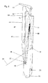
- Fig. 2 is a side view of the lift with fully extended Platform
- Fig. 3 is a side view of the lift with partially extended platform
- Fig. 5 is a side view of the retracted lift with retracted platform
- Fig. 6 is a side part of the first part platform
- Fig. 7 is a side part of the second part platform, which on the in 6 slides past side when extending and the extension of the platform conditionally.
- Fig. 1 is a lift 10 in a perspective view in a position shown above as the third position.
- a Base plate 6 On a Base plate 6 are two mutually mirror-symmetrical stator 8 and 8 ' attached to each of which an upper lever 12 or 12 'and a parallel thereto extending lower lever 13 or 13 'by a respective articulation point 21, 23 (Fig. 2) are pivotally hinged at their ends.
- At the other one End of the upper lever 12 and 12 'and the lower lever 13 and 13' is an edge profile 16 or 16 'by a respective articulation point 18 and 19, respectively pivotally hinged so that the pivot points 18, 19, 21, 23, the four Corner points of, from each of the uprights 8, 8 ', the parallel to each other aligned levers 12, 12 'and from the one end of the associated Kantprofils 16, 16 'existing parallelogram form.
- first part platform 28 At the other ends of the edge profiles 16, 16 'is a first part platform 28, which has two side parts 30 and 30 '.
- first Sub-platform 28 At the first Sub-platform 28 is in turn a second sub-platform 44 to this slidably mounted, the two side parts 42 and 42 'has.
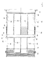
- Fig. 2 shows the lift in the second position, in which the sub-platforms a form a common, horizontally oriented platform, which is located on the Level of the vehicle interior is located.
- the lift 10 is of two Hydraulic cylinders 11, 11 'moves diagonally through the respective Run parallelogram and the respective stand 8 in the articulation point 23rd are pivotally mounted, around which the lower lever 13 pivotally is.
- the associated hydraulic unit is, as well as the associated Control unit, not shown.
- transverse edge profile 15 On the edge profile 16 is in its upper third of a transverse edge profile 15 by means a bearing pin 25 pivotally and in the direction of the stand attached pointing.
- the free end of this transverse edge profile 15 is by means of a joint 27 hinged to one end of a support edge profile 14; the Attachment of the other end of the support square profile is below described.
- the edge profile 16 At the lower end of the edge profile 16 is a bearing 26 and at the bottom of the supporting edge profile 14 is a bearing 26 in the direction of the stator. 8 offset bearing 20 for pivotally mounting the first part platform 28 provided.
- the first sub-platform 28 is shown 6 in the second or third position defined above, in which the Platform occupies its horizontal position.
- the side part 30 of the first Part platform 28 (FIG. 6) has a pin 32 which fits into the bearing 26 of the edge profile 16 engages and a pin 33, with the bearing 20 in Intervention is.
- a rectilinear slot 38 located in the vicinity of the bearing 26 and adjacent to the upper edge of the side member 30 in Fig. 6 begins and ends adjacent to its lower edge.
- the second side part 30 ' (FIG. 4) is mirror-symmetrical to the side part 30 built up. Similarly, every element described above has its own in it the manner described symmetrical equivalent, with the corresponding reference numeral is marked with apostrophe.
- the Side part 30 ' is connected to the side part 30 by two webs 48, the perpendicular to the side parts 30 and 30 'extend. At these bars 48 are attached between these extending struts 50.
- the two outermost struts are attached to the side part 30 and 30 '.
- the two webs 48, and the struts 50 form a flat support for a Expanded metal mesh 52. When the lift is in the second or third position In which the second part platform is extended forms the Expanded metal 52 a horizontally extending flat surface on which loads, in particular, to be able to roll and roll.
- a sliding block 66 (Fig. 2), in the one Pin 40 rotatably engaged about a horizontal axis, which at the lower lever 13 facing the end of the side part 42 of the second Part platform 44 (Fig. 7) is attached.
- the side guide of the sliding block takes on the inside of the sub-platform 28, the side part 42 and on the outside of a disc 46, which on the sliding block 66 screwed on and has a diameter that is larger than that Slot width.
- a Attachment 22 for a rope 24 for a rope 24, the purpose of which will be described later.
- the Rope 24 will normally be a steel rope.
- a guide roller 36 and on the the lower lever 13 opposite end of the side part 30 is a further deflection roller 34 is provided, around which the cable 24 and around Sliding stone 66 is guided, where it ends.
- the platform is the sliding block 66 under pressure on the piston rod 68th at.
- the cylinder of the gas spring 70 is at the Pulley 34 adjacent end of the slot 38 on the side part 30th appropriate. If you exercise in the attachment 22 a tensile force on the Rope 24 off, the sliding block 66 moves toward the gas spring 70 and finally pushes the piston rod 68 into the cylinder of the Gas spring into it.
- the side part 42 of the second part platform corresponds in his Longitudinal extent about that of the side part 30. In its middle Section extend upper and lower edge of the side part 42 parallel to each other.
- the side part 42 On the left in Fig. 7, the lower lever 13th facing side, the side part 42 on its underside a Contour 53, which is designed so that the lower edge of the side part 42nd when the second sub-platform 44 is extended, with the lower edge of the side part 30 is aligned.
- the upper edge of the side part 42 is aligned in In this case, with the upper edge of the side part 30.
- the contour 53 is u.a. also necessary for the sub-platform 44 in the sub-platform 28th can push in.
- the two side parts 42, 42 'of the second part platform are by means of two Webs 54 connected (Fig. 4). Between the two webs 54 are Struts 56 and the two outermost struts are in turn to the attached to both side parts 42 and 42 '.
- the webs 54 and struts 56 together form a level support for an expanded metal mesh 58.
- Im extended state of the lift 10 which is shown in Figures 1 and 2, are the expanded metal mesh 52 and 58 of the two sub-platforms gapless in a horizontal plane.
- the struts 56 are straight until below the free ends of Side parts 42, 42 'led out.
- a slot 62 is provided, which in the area, in the respective outer edges run parallel to each other, also runs parallel to these and has its main section there.
- Fig. 7 left portion of the side part is the slot 62 to a steep section angled and approaches in the direction of the pin 40 out under a predetermined angle (see Fig. 7) of the upper edge of the side part 42nd at.
- a roller 60 runs on a pin 64, the side part 30 (Fig. 6) is attached.
- a fold-out roll stop 72 (Fig. 2). in the unfolded state is the top 74 in extension of the Expanded metal grid 58 and then forms the transition from the platform to Street. In this position, a wheelchair on the second part platform 44th reach. To roll back while lifting the wheelchair prevent the fold-out roll stop 72 during the lifting and Lowering of the lift folded up so that their top 74th forms an approximately right angle with the expanded metal grid 58.
- the relative position of the individual components of the lift to each other in the the loading serving third position is shown in Fig.1.
- the Sliding shoes 17, 17 'in this case have no contact with the levers 13, 13', so that the support edge profile 14 no force on the pin 33 on the Platform can exercise and the platform around the pin 32 down would swing away, if not from the ropes 24, 24 'in the drawn position would be held relative to the edge profile 16.
- each rope 24, 24 ' is chosen for this purpose so that it due to the force exerted by the weight of the platform on the rope force selected according to this force gas spring 70 at the presses retracted stop, accordingly pretensions and thereby the Relative position of platform and edge profile 16 secures each other.
- This relief of the rope means a corresponding decrease of outside of the rope on the gas spring 70 force applied, so now the force stored in the gas spring can begin, over the Piston rod 68 the sliding block 66 in the direction of the free end of the Slit 38 to move. Since the sliding block on the one hand with the rope 24 and on the other hand via the pin 40 with the second part platform connected, causes the displacement of the sliding block on the one hand, that the rope 24 remains taut and on the other hand, that the second Part platform 44 follows the movement of the sliding block and about parallel to its main plane into the area of the first sub-platform 28 moved into it.
- Fig. 3 shows the state in which the distance between the roller 36 and the attachment 22 due to the pivotal movement of the upper lever 12th has shortened by an amount equal to the maximum extension length of the Gas spring 70 corresponds. In this case, this no longer exerts pressure on the sliding block 66 and thus no more train on the rope 24.
- the roller 60 in the slot 62 is then at the transition from Steep section of the slot 62 in the straight main section (Kink).
- the slot 38 of the first sub-platform 28 extends to this first part of the pivoting movement now - from the upper lever 12th seen from - not downwards, but slightly inclined upwards.
- the sliding block 66 When moving from the shown in Fig. 2 extended state in 3, the sliding block 66 has on the Top edge of the first part platform 28 and the pin 64 on the Lower edge of the second part platform 44 moved. This creates a Height difference X between the lower edge of the second part platform 44th and the expanded metal grid 58. If the upper lever 12 continues in Pivoting counterclockwise, so slides the second part platform 44th solely by the influence of gravity on the roller 60 and the Sliding stone 66 in the slots 62 and 38 in the room of the first Part platform 28 between the side parts 30 and 30 'into it. she will thereby braked by the rope 24.
- the sliding block 66 is located on the gas spring 70 opposite end of the slot 38th
- gas spring 70 serves the purpose of the first part the Einschwenkamba the second part platform 44 to effect.
- first part platform and a second part platform Telescoping mechanism can also be transferred to vehicle lifts, their first and second sub-platforms each consist of two Sub-sub-platforms exist. These can, for example, in the Rest position of the vehicle lift on in the US Patent 6,086,314 be kind of unfolded. For lifts whose width can correspond to the width of the vehicle door, in this way be achieved that even in the rest position of the vehicle lift a Person can enter the vehicle through the vehicle door by she walks between the two parts of the sub-platforms.
Landscapes
- Public Health (AREA)
- Health & Medical Sciences (AREA)
- Life Sciences & Earth Sciences (AREA)
- Animal Behavior & Ethology (AREA)
- General Health & Medical Sciences (AREA)
- Veterinary Medicine (AREA)
- Handcart (AREA)
- Loading Or Unloading Of Vehicles (AREA)
- Escalators And Moving Walkways (AREA)
- Organic Low-Molecular-Weight Compounds And Preparation Thereof (AREA)
- Vehicle Step Arrangements And Article Storage (AREA)
- Forklifts And Lifting Vehicles (AREA)
- Vehicle Cleaning, Maintenance, Repair, Refitting, And Outriggers (AREA)
Abstract
Description
Claims (14)
- Fahrzeuglift für Lasten, insbesondere für Rollstühle, mit einer ersten Teil-Plattform (28) und mindestens einer zweiten Teil-Plattform (44), von denen die erste Teil-Plattform (28) um eine horizontale Schwenkachse (Lager 26) beweglich an einem Träger (Kantprofil 16) mittels eines den Träger enthaltenden Parallelogrammgestänges (8,12,13,16, 8',12',13', 16') mit dem Kraftfahrzeug verbindbar ist und aus einer Ruhestellung, in der die Teil-Plattformen eine im Wesentlichen vertikale Position einnehmen, durch eine Schwenkbewegung um die Schwenkachse in eine erste Arbeitsstellung bringbar ist, in der die Teil-Plattformen (28, 44) eine Gesamt-Plattform bilden und aus der die Gesamt-Plattform durch Verschiebung parallel zu sich selbst in zumindest eine weitere Arbeitsstellung und zurück bringbar ist,
dadurch gekennzeichnet, dass die zweite Teil-Plattform (44), die ggf. weitere Unterplattformen aufnimmt, an der ersten Teil-Plattform (28) teleskopierbar befestigt und geführt ist und dass zumindest ein Seil (24) mit seinem einen Ende beabstandet von der Schwenkachse an einem relativ zu den Teil-Plattformen beweglichen Element (Träger 16, Stützkantprofil 14 o. dgl.) angebracht und mit seinem anderen Ende derart an der zweiten Teil-Plattform befestigt und so geführt ist, dass die zweite Teil-Plattform (44) während der Schwenkbewegung etwa parallel zu ihrer Hauptebene aus der ersten Teil-Plattform heraus- und bei einer Gegenschwenkbewegung hineingefahren wird. - Fahrzeuglift nach Anspruch 1, dessen erste Teil-Plattform (28) zwei beabstandete Seitenteile (30, 30') aufweist, in denen je ein geradliniger Schlitz (38), beginnend in der Nähe der Schwenkachse, aus dem Bereich der in den Arbeitsstellungen der ersten Teil-Plattform oben liegenden Kanten der Seitenteile (30, 30') schräg in Richtung auf die anderen Kanten der Seitenteile verläuft.
- Fahrzeuglift nach Anspruch 1 oder 2, dessen zweite Teil-Plattform (44) ebenfalls beidseitig je ein Seitenteil (42) aufweist, in dem ein Schlitz (62) ausgebildet ist, der bei in Arbeitsstellung befindlicher zweiter Teil-Plattform, beginnend ungefähr in der Hälfte von deren Längserstreckung und in der Nähe der oberen Kante des Seitenteils (42) zunächst einen nach unten bis zu einer Knickstelle verlaufenden Steilabschnitt hat und anschließend an die Knickstelle in seinem Hauptabschnitt weitgehend horizontal verläuft.
- Fahrzeuglift nach Anspruch 2, dadurch gekennzeichnet, dass in jedem der beiden Schlitze (38) der ersten Teil-Plattform je ein Kulissenstein (66) läuft und an diesen Kulissensteinen die zweite Teil-Plattform (44) um eine horizontale Achse (Zapfen 40) schwenkbar befestigt ist.
- Fahrzeuglift nach Anspruch 4, dadurch gekennzeichnet, dass das Seil (24) von seinem Anlenkpunkt an dem Träger (Kantprofil 16) zunächst über eine erste Rolle (36), die am Seitenteil (30) der ersten Teil-Plattform (28) etwa in dessen halber Längserstreckung befestigt ist, danach über eine zweite Rolle (34), die an dem der Schwenkachse (26) abgewandten Ende des Seitenteils (42) angebracht ist, zu seinem Anlenkpunkt am Kulissenstein (66) geführt ist.
- Fahrzeuglift nach einem der Ansprüche 4 oder 5, mit zumindest jeweils einer Gasdruckfeder (70), die an den Seitenteilen (30) befestigt ist, zum Straffen des zugehörigen Seils (24).
- Fahrzeuglift nach Anspruch 6, dadurch gekennzeichnet, dass die Gasdruckfedern (70) an dem zugehörigen Kulissenstein (66) angreift.
- Fahrzeuglift nach einem der Ansprüche 6 oder 7, dadurch gekennzeichnet dass die Gasdruckfeder (70) das zugeordnete Seil (24) mindestens beim Schwenken der Teil-Plattformen aus deren Arbeits- in deren Ruhestellung strafft, bis die zweite Teil-Plattform allein aufgrund ihrer Schwerkraft und der Neigung des Schlitzes (62) gegen die Horizontale in diesem in Richtung auf das Parallelogrammgestänge hin gleitfähig ist.
- Fahrzeuglift nach Anspruch 8, dadurch gekennzeichnet, dass die Gasdruckfeder (70) das zugehörige Seil (24) mindestens solange strafft, bis die Schwerkraft der zweiten Teil-Plattform die Straffung des Seils übernimmt.
- Fahrzeuglift nach mindestens einem der vorhergehenden Ansprüche, gekennzeichnet durch eine je Rolle (60) mit horizontaler Drehachse, die an dem der Schwenkachse abgekehrten Ende der Seitenteile der ersten Teil-Plattform vorgesehen ist, in den zugeordneten, entlang der Seitenteile der zweiten Teil-Plattform verlaufenden Schlitz (62) eingreift und dort geführt ist.
- Fahrzeuglift nach Anspruch 9, bei dem sich die Knickstelle im Schlitz (62) an der Stelle befindet, die die Rolle (60) einnimmt, wenn der Schlitz der ersten Teil-Plattform während der Schwenkbewegung horizontal ausgerichtet ist.
- Fahrzeuglift nach mindestens einem der Ansprüche 1 - 11, bei dem das Seil (24) so lang bemessen ist, dass die erste Teil-Plattform horizontal ausgerichtet ist, wenn sich der Kulissenstein (66) an seinem der Schwenkachse (Lager 26) abgekehrten Ende des Schlitzes (38) bei voll vorgespannter Gasdruckfeder (70) befindet.
- Fahrzeuglift nach Anspruch 12, bei dem das Seil bzw. die Seile (24, 24') die Halterung für die erste Teil-Plattform in deren horizontaler Ausrichtung bildet/bilden.
- Fahrzeuglift nach mindestens einem der vorstehenden Ansprüche, bei dem für die Überführung der Teil-Plattformen aus deren Arbeits- in die Ruhestellung eine, aus einem Stütz-Kantprofil (14) und einem mit diesem mittels eines Gelenkes (27) verbundenen Quer-Kantprofil (15) bestehende Gelenkhebelkonstruktion vorgesehen ist, dadurch gekennzeichnet, dass das Seil (24) mit seinem einen Ende beabstandet von dem Lager (26) der ersten Teil-Plattform (28) an der Gelenkhebelkonstruktion, insbesondere an dem Stütz-Kantprofil (14) und benachbart zu dem Gelenk (27) befestigt ist.
Applications Claiming Priority (2)
| Application Number | Priority Date | Filing Date | Title |
|---|---|---|---|
| DE20309868U DE20309868U1 (de) | 2003-06-25 | 2003-06-25 | Fahrzeuglift für Lasten, insbesondere für Rollstühle |
| DE20309868U | 2003-06-25 |
Publications (3)
| Publication Number | Publication Date |
|---|---|
| EP1491173A1 EP1491173A1 (de) | 2004-12-29 |
| EP1491173A9 true EP1491173A9 (de) | 2005-07-06 |
| EP1491173B1 EP1491173B1 (de) | 2008-06-18 |
Family
ID=33395179
Family Applications (1)
| Application Number | Title | Priority Date | Filing Date |
|---|---|---|---|
| EP04102659A Expired - Lifetime EP1491173B1 (de) | 2003-06-25 | 2004-06-11 | Fahrzeuglift für Lasten, insbesondere für Rollstühle |
Country Status (3)
| Country | Link |
|---|---|
| EP (1) | EP1491173B1 (de) |
| AT (1) | ATE398435T1 (de) |
| DE (2) | DE20309868U1 (de) |
Families Citing this family (15)
| Publication number | Priority date | Publication date | Assignee | Title |
|---|---|---|---|---|
| NL1033716C2 (nl) * | 2007-04-18 | 2008-10-21 | Pieter John Van Mullekom | Liftinrichting voor een voertuig. |
| GB2463886B (en) | 2008-09-26 | 2012-07-18 | Passenger Lift Services Ltd | Lifts |
| DE202009002451U1 (de) | 2009-02-23 | 2009-06-10 | Kollewe, Dieter, Dr. | Ladelift für ein Kraftfahrzeug |
| EP2641576B1 (de) | 2012-03-21 | 2015-04-22 | AMF-Bruns GmbH & Co. KG | Fahrzeuglift |
| DE202012002833U1 (de) | 2012-03-21 | 2013-06-24 | Gustav Bruns Maschinenbau und Förderanlagen GmbH & Co. KG | Fahrzeuglift |
| EP2641575B1 (de) | 2012-03-21 | 2015-05-13 | AMF-Bruns GmbH & Co. KG | Fahrzeuglift mit Vorspanneinrichtung |
| DE202012002832U1 (de) | 2012-03-21 | 2013-06-25 | Gustav Bruns Maschinenbau und Förderanlagen GmbH & Co. KG | Fahrzeuglift mit Vorspanneinrichtung |
| USD708412S1 (en) | 2012-10-23 | 2014-07-01 | Amf-Bruns Gmbh & Co. Kg | Support arm for a wheel chair lift |
| ITMI20130378A1 (it) * | 2013-03-13 | 2014-09-14 | Car Oil System S P A | Sollevatore per sedie a rotelle, particolarmente per veicoli adibiti al trasporto di persone diversamente abili. |
| DK2818148T3 (da) | 2013-06-24 | 2019-05-06 | Autolift S R L | Kørestolslift |
| CN103735372B (zh) * | 2014-01-14 | 2016-08-24 | 深圳市汇利堡汽车技术开发有限公司 | 升降装置及其可折叠平台机构、可折叠组件和设计方法 |
| CN106798614B (zh) * | 2017-01-24 | 2018-10-30 | 肖三美 | 一种福祉车 |
| DE102017110003A1 (de) * | 2017-05-09 | 2018-11-15 | MCS medical concept solutions GmbH | Befestigungsvorrichtung zur Befestigung eines Thoraxkompressionssystems |
| DE102019203460A1 (de) * | 2019-03-14 | 2020-09-17 | Siemens Healthcare Gmbh | Patiententisch mit einer Auflagefläche für einen Patienten |
| US20220323276A1 (en) * | 2021-04-12 | 2022-10-13 | Scott Ivan Fenton | Extendable platform lift assembly |
Family Cites Families (11)
| Publication number | Priority date | Publication date | Assignee | Title |
|---|---|---|---|---|
| US4479753A (en) * | 1982-05-19 | 1984-10-30 | Transportation Design & Technology, Inc. | Wheelchair lift for passenger vehicles |
| DE3838560A1 (de) * | 1988-11-14 | 1990-05-17 | Ibeg Masch & Geraetebau | Heb- und senkbarer einstieg fuer fahrzeuge |
| US4984955A (en) * | 1989-02-23 | 1991-01-15 | Mccullough Robert C | Lift apparatus |
| DE3922511C2 (de) * | 1989-07-08 | 1998-03-12 | Evobus Gmbh | Hebevorrichtung |
| US5445488A (en) * | 1992-07-28 | 1995-08-29 | Ricon Corporation | Locking wheelchair lift |
| DE19503079C2 (de) * | 1995-02-01 | 1998-07-09 | Deutsche Waggonbau Ag | Überfahrrampe für Rollstuhlfahrer in Fahrzeugen mit Niederflureinstiegen, insbesondere Reisezugwagen |
| JP3745044B2 (ja) * | 1996-09-17 | 2006-02-15 | 株式会社オーテックジャパン | 車両の車椅子用昇降装置 |
| US6086314A (en) | 1997-08-15 | 2000-07-11 | Ricon Corporation | Foldable platform wheelchair lift |
| DE69936644T2 (de) | 1998-05-29 | 2008-04-10 | Ricon Corp., Panorama | Rollstuhllift mit faltbarer hebeplattform |
| DE29902687U1 (de) * | 1999-02-16 | 1999-05-20 | MBB Liftsystems AG, 27777 Ganderkesee | Hubvorrichtung für Fahrzeuge zur Erleichterung des Ein- und Ausstiegs mobilitätsbehinderter Personen |
| US6692217B1 (en) * | 1999-04-29 | 2004-02-17 | The Braun Corporation | Liftable platform having isolated hydraulically-moveable rollstop |
-
2003
- 2003-06-25 DE DE20309868U patent/DE20309868U1/de not_active Expired - Lifetime
-
2004
- 2004-06-11 DE DE502004007375T patent/DE502004007375D1/de not_active Expired - Lifetime
- 2004-06-11 EP EP04102659A patent/EP1491173B1/de not_active Expired - Lifetime
- 2004-06-11 AT AT04102659T patent/ATE398435T1/de active
Also Published As
| Publication number | Publication date |
|---|---|
| DE20309868U1 (de) | 2004-11-04 |
| DE502004007375D1 (de) | 2008-07-31 |
| EP1491173A1 (de) | 2004-12-29 |
| ATE398435T1 (de) | 2008-07-15 |
| EP1491173B1 (de) | 2008-06-18 |
Similar Documents
| Publication | Publication Date | Title |
|---|---|---|
| DE102004016272B4 (de) | Fluggasttreppe oder Fluggastbrücke | |
| EP1538271B1 (de) | Erweiterbarer Container | |
| EP1491173A9 (de) | Fahrzeuglift für Lasten, insbesondere für Rollstühle | |
| DE102017101113B3 (de) | Teleskopausleger mit Stangenabspannsystem für einen Mobilkran und Abspannverfahren hierfür | |
| DE60120299T2 (de) | Seilanordnung für einen Turmkran | |
| DE3735262A1 (de) | Faltbare maschine fuer die handhabung und den transport von lasten | |
| DE60104934T2 (de) | Teleskopische Stuktur und Hubarbeitsbühne mit solcher Struktur | |
| DE60007488T2 (de) | Zusammenklappvorrichtung eines Kranauslegers mit ineinandersetzbaren Elementen | |
| EP0267542B1 (de) | Fahrwerk für eine verfahrbare Tribüne | |
| DE2801831A1 (de) | Abrollsicherung fuer ladebordwaende | |
| DE3619124C2 (de) | ||
| DE102020126556B3 (de) | Mobile eventbühne und verfahren zum aufbau der mobilen eventbühne | |
| DE3329210A1 (de) | Schraegaufzug | |
| DE202005020324U1 (de) | Bewegliche Bühne | |
| DE1247584B (de) | Zusammenlegbarer Turmdrehkran | |
| DE19822633A1 (de) | Arbeitsbühne mit einem durch ein Scherenhubwerk höhenverstellbaren Arbeitsboden | |
| DE10114359A1 (de) | Mobile Fördereinrichtung mit Verteilermast und begehbaren Pritschen | |
| EP2318301B1 (de) | Hebebühne | |
| DE202005004862U1 (de) | Hubvorrichtung für Kraftfahrzeuge | |
| EP0346652B1 (de) | Lastkraftwagen mit einer Ladepritsche und einem Aufbau | |
| DE102014104072B4 (de) | Zusammenklappbares schienengeführtes Liftsystem | |
| DE29909974U1 (de) | Geländer mit einer absenkbaren Griffstange | |
| DE202008017391U1 (de) | Abstützvorrichtung für ein Auslegerfahrzeug | |
| DE102006001787B4 (de) | Zelt mit ausfahrbarer Zeltdachspitze | |
| DE10223598B4 (de) | Container |
Legal Events
| Date | Code | Title | Description |
|---|---|---|---|
| PUAI | Public reference made under article 153(3) epc to a published international application that has entered the european phase |
Free format text: ORIGINAL CODE: 0009012 |
|
| AK | Designated contracting states |
Kind code of ref document: A1 Designated state(s): AT BE BG CH CY CZ DE DK EE ES FI FR GB GR HU IE IT LI LU MC NL PL PT RO SE SI SK TR |
|
| AX | Request for extension of the european patent |
Extension state: AL HR LT LV MK |
|
| 17P | Request for examination filed |
Effective date: 20050531 |
|
| AKX | Designation fees paid |
Designated state(s): AT BE BG CH CY CZ DE DK EE ES FI FR GB GR HU IE IT LI LU MC NL PL PT RO SE SI SK TR |
|
| GRAP | Despatch of communication of intention to grant a patent |
Free format text: ORIGINAL CODE: EPIDOSNIGR1 |
|
| GRAS | Grant fee paid |
Free format text: ORIGINAL CODE: EPIDOSNIGR3 |
|
| GRAA | (expected) grant |
Free format text: ORIGINAL CODE: 0009210 |
|
| AK | Designated contracting states |
Kind code of ref document: B1 Designated state(s): AT BE BG CH CY CZ DE DK EE ES FI FR GB GR HU IE IT LI LU MC NL PL PT RO SE SI SK TR |
|
| REG | Reference to a national code |
Ref country code: GB Ref legal event code: FG4D Free format text: NOT ENGLISH |
|
| REF | Corresponds to: |
Ref document number: 502004007375 Country of ref document: DE Date of ref document: 20080731 Kind code of ref document: P |
|
| REG | Reference to a national code |
Ref country code: CH Ref legal event code: EP |
|
| REG | Reference to a national code |
Ref country code: IE Ref legal event code: FG4D Free format text: LANGUAGE OF EP DOCUMENT: GERMAN |
|
| REG | Reference to a national code |
Ref country code: CH Ref legal event code: NV Representative=s name: E. BLUM & CO. AG PATENT- UND MARKENANWAELTE VSP |
|
| PG25 | Lapsed in a contracting state [announced via postgrant information from national office to epo] |
Ref country code: SI Free format text: LAPSE BECAUSE OF FAILURE TO SUBMIT A TRANSLATION OF THE DESCRIPTION OR TO PAY THE FEE WITHIN THE PRESCRIBED TIME-LIMIT Effective date: 20080618 Ref country code: FI Free format text: LAPSE BECAUSE OF FAILURE TO SUBMIT A TRANSLATION OF THE DESCRIPTION OR TO PAY THE FEE WITHIN THE PRESCRIBED TIME-LIMIT Effective date: 20080618 |
|
| PG25 | Lapsed in a contracting state [announced via postgrant information from national office to epo] |
Ref country code: PL Free format text: LAPSE BECAUSE OF FAILURE TO SUBMIT A TRANSLATION OF THE DESCRIPTION OR TO PAY THE FEE WITHIN THE PRESCRIBED TIME-LIMIT Effective date: 20080618 |
|
| PG25 | Lapsed in a contracting state [announced via postgrant information from national office to epo] |
Ref country code: PT Free format text: LAPSE BECAUSE OF FAILURE TO SUBMIT A TRANSLATION OF THE DESCRIPTION OR TO PAY THE FEE WITHIN THE PRESCRIBED TIME-LIMIT Effective date: 20081118 Ref country code: ES Free format text: LAPSE BECAUSE OF FAILURE TO SUBMIT A TRANSLATION OF THE DESCRIPTION OR TO PAY THE FEE WITHIN THE PRESCRIBED TIME-LIMIT Effective date: 20080929 Ref country code: CZ Free format text: LAPSE BECAUSE OF FAILURE TO SUBMIT A TRANSLATION OF THE DESCRIPTION OR TO PAY THE FEE WITHIN THE PRESCRIBED TIME-LIMIT Effective date: 20080618 Ref country code: SE Free format text: LAPSE BECAUSE OF FAILURE TO SUBMIT A TRANSLATION OF THE DESCRIPTION OR TO PAY THE FEE WITHIN THE PRESCRIBED TIME-LIMIT Effective date: 20080918 |
|
| REG | Reference to a national code |
Ref country code: IE Ref legal event code: FD4D |
|
| PG25 | Lapsed in a contracting state [announced via postgrant information from national office to epo] |
Ref country code: SK Free format text: LAPSE BECAUSE OF FAILURE TO SUBMIT A TRANSLATION OF THE DESCRIPTION OR TO PAY THE FEE WITHIN THE PRESCRIBED TIME-LIMIT Effective date: 20080618 Ref country code: RO Free format text: LAPSE BECAUSE OF FAILURE TO SUBMIT A TRANSLATION OF THE DESCRIPTION OR TO PAY THE FEE WITHIN THE PRESCRIBED TIME-LIMIT Effective date: 20080618 |
|
| PLBE | No opposition filed within time limit |
Free format text: ORIGINAL CODE: 0009261 |
|
| STAA | Information on the status of an ep patent application or granted ep patent |
Free format text: STATUS: NO OPPOSITION FILED WITHIN TIME LIMIT |
|
| PG25 | Lapsed in a contracting state [announced via postgrant information from national office to epo] |
Ref country code: IE Free format text: LAPSE BECAUSE OF FAILURE TO SUBMIT A TRANSLATION OF THE DESCRIPTION OR TO PAY THE FEE WITHIN THE PRESCRIBED TIME-LIMIT Effective date: 20080618 Ref country code: EE Free format text: LAPSE BECAUSE OF FAILURE TO SUBMIT A TRANSLATION OF THE DESCRIPTION OR TO PAY THE FEE WITHIN THE PRESCRIBED TIME-LIMIT Effective date: 20080618 Ref country code: DK Free format text: LAPSE BECAUSE OF FAILURE TO SUBMIT A TRANSLATION OF THE DESCRIPTION OR TO PAY THE FEE WITHIN THE PRESCRIBED TIME-LIMIT Effective date: 20080618 Ref country code: BG Free format text: LAPSE BECAUSE OF FAILURE TO SUBMIT A TRANSLATION OF THE DESCRIPTION OR TO PAY THE FEE WITHIN THE PRESCRIBED TIME-LIMIT Effective date: 20080918 |
|
| 26N | No opposition filed |
Effective date: 20090319 |
|
| BERE | Be: lapsed |
Owner name: APENER MASCHINENBAU UND FORDERANLAGEN GUSTAV BRUNS Effective date: 20090630 |
|
| PG25 | Lapsed in a contracting state [announced via postgrant information from national office to epo] |
Ref country code: MC Free format text: LAPSE BECAUSE OF NON-PAYMENT OF DUE FEES Effective date: 20090630 |
|
| PG25 | Lapsed in a contracting state [announced via postgrant information from national office to epo] |
Ref country code: BE Free format text: LAPSE BECAUSE OF NON-PAYMENT OF DUE FEES Effective date: 20090630 |
|
| PG25 | Lapsed in a contracting state [announced via postgrant information from national office to epo] |
Ref country code: GR Free format text: LAPSE BECAUSE OF FAILURE TO SUBMIT A TRANSLATION OF THE DESCRIPTION OR TO PAY THE FEE WITHIN THE PRESCRIBED TIME-LIMIT Effective date: 20080919 |
|
| PG25 | Lapsed in a contracting state [announced via postgrant information from national office to epo] |
Ref country code: LU Free format text: LAPSE BECAUSE OF NON-PAYMENT OF DUE FEES Effective date: 20090611 |
|
| PG25 | Lapsed in a contracting state [announced via postgrant information from national office to epo] |
Ref country code: HU Free format text: LAPSE BECAUSE OF FAILURE TO SUBMIT A TRANSLATION OF THE DESCRIPTION OR TO PAY THE FEE WITHIN THE PRESCRIBED TIME-LIMIT Effective date: 20081219 |
|
| PG25 | Lapsed in a contracting state [announced via postgrant information from national office to epo] |
Ref country code: TR Free format text: LAPSE BECAUSE OF FAILURE TO SUBMIT A TRANSLATION OF THE DESCRIPTION OR TO PAY THE FEE WITHIN THE PRESCRIBED TIME-LIMIT Effective date: 20080618 |
|
| PG25 | Lapsed in a contracting state [announced via postgrant information from national office to epo] |
Ref country code: CY Free format text: LAPSE BECAUSE OF FAILURE TO SUBMIT A TRANSLATION OF THE DESCRIPTION OR TO PAY THE FEE WITHIN THE PRESCRIBED TIME-LIMIT Effective date: 20080618 |
|
| PGFP | Annual fee paid to national office [announced via postgrant information from national office to epo] |
Ref country code: NL Payment date: 20140618 Year of fee payment: 11 Ref country code: CH Payment date: 20140620 Year of fee payment: 11 Ref country code: AT Payment date: 20140618 Year of fee payment: 11 |
|
| REG | Reference to a national code |
Ref country code: CH Ref legal event code: PL |
|
| REG | Reference to a national code |
Ref country code: AT Ref legal event code: MM01 Ref document number: 398435 Country of ref document: AT Kind code of ref document: T Effective date: 20150611 |
|
| REG | Reference to a national code |
Ref country code: NL Ref legal event code: MM Effective date: 20150701 |
|
| PG25 | Lapsed in a contracting state [announced via postgrant information from national office to epo] |
Ref country code: CH Free format text: LAPSE BECAUSE OF NON-PAYMENT OF DUE FEES Effective date: 20150630 Ref country code: LI Free format text: LAPSE BECAUSE OF NON-PAYMENT OF DUE FEES Effective date: 20150630 Ref country code: NL Free format text: LAPSE BECAUSE OF NON-PAYMENT OF DUE FEES Effective date: 20150701 |
|
| PG25 | Lapsed in a contracting state [announced via postgrant information from national office to epo] |
Ref country code: AT Free format text: LAPSE BECAUSE OF NON-PAYMENT OF DUE FEES Effective date: 20150611 |
|
| REG | Reference to a national code |
Ref country code: FR Ref legal event code: PLFP Year of fee payment: 13 |
|
| REG | Reference to a national code |
Ref country code: FR Ref legal event code: PLFP Year of fee payment: 14 |
|
| REG | Reference to a national code |
Ref country code: FR Ref legal event code: PLFP Year of fee payment: 15 |
|
| REG | Reference to a national code |
Ref country code: DE Ref legal event code: R081 Ref document number: 502004007375 Country of ref document: DE Owner name: BRUNS HOLDING GMBH & CO. KG, DE Free format text: FORMER OWNER: APENER MASCHINENBAU UND FOERDERANLAGEN GUSTAV BRUNS GMBH & CO KG, 26689 APEN, DE |
|
| REG | Reference to a national code |
Ref country code: GB Ref legal event code: 732E Free format text: REGISTERED BETWEEN 20220707 AND 20220713 |
|
| PGFP | Annual fee paid to national office [announced via postgrant information from national office to epo] |
Ref country code: FR Payment date: 20230620 Year of fee payment: 20 |
|
| PGFP | Annual fee paid to national office [announced via postgrant information from national office to epo] |
Ref country code: IT Payment date: 20230630 Year of fee payment: 20 Ref country code: GB Payment date: 20230622 Year of fee payment: 20 |
|
| PGFP | Annual fee paid to national office [announced via postgrant information from national office to epo] |
Ref country code: DE Payment date: 20230707 Year of fee payment: 20 |
|
| REG | Reference to a national code |
Ref country code: DE Ref legal event code: R071 Ref document number: 502004007375 Country of ref document: DE |
|
| PG25 | Lapsed in a contracting state [announced via postgrant information from national office to epo] |
Ref country code: GB Free format text: LAPSE BECAUSE OF EXPIRATION OF PROTECTION Effective date: 20240610 |
|
| PG25 | Lapsed in a contracting state [announced via postgrant information from national office to epo] |
Ref country code: GB Free format text: LAPSE BECAUSE OF EXPIRATION OF PROTECTION Effective date: 20240610 |