EP1491285A2 - Device and method for dynamically screwing components, in particular for bearing and transmission assemblies - Google Patents
Device and method for dynamically screwing components, in particular for bearing and transmission assemblies Download PDFInfo
- Publication number
- EP1491285A2 EP1491285A2 EP04014931A EP04014931A EP1491285A2 EP 1491285 A2 EP1491285 A2 EP 1491285A2 EP 04014931 A EP04014931 A EP 04014931A EP 04014931 A EP04014931 A EP 04014931A EP 1491285 A2 EP1491285 A2 EP 1491285A2
- Authority
- EP
- European Patent Office
- Prior art keywords
- planet carrier
- rotary drive
- drive device
- switched
- torque
- Prior art date
- Legal status (The legal status is an assumption and is not a legal conclusion. Google has not performed a legal analysis and makes no representation as to the accuracy of the status listed.)
- Granted
Links
Images

Classifications
-
- B—PERFORMING OPERATIONS; TRANSPORTING
- B23—MACHINE TOOLS; METAL-WORKING NOT OTHERWISE PROVIDED FOR
- B23P—METAL-WORKING NOT OTHERWISE PROVIDED FOR; COMBINED OPERATIONS; UNIVERSAL MACHINE TOOLS
- B23P19/00—Machines for simply fitting together or separating metal parts or objects, or metal and non-metal parts, whether or not involving some deformation; Tools or devices therefor so far as not provided for in other classes
- B23P19/04—Machines for simply fitting together or separating metal parts or objects, or metal and non-metal parts, whether or not involving some deformation; Tools or devices therefor so far as not provided for in other classes for assembling or disassembling parts
- B23P19/06—Screw or nut setting or loosening machines
- B23P19/065—Arrangements for torque limiters or torque indicators in screw or nut setting machines
- B23P19/066—Arrangements for torque limiters or torque indicators in screw or nut setting machines by electrical means
Definitions
- the present invention relates to a device according to the preamble of claim 1 and a method for the dynamic screwing of components, in particular of bearing and gear units.
- the invention is therefore based on the object of providing a device and a method for the dynamic screwing of components, in particular of bearing and gear units, by means of which the screwing process becomes more reliable.
- this object is achieved in the generic device in that both planet carriers are rotatably mounted and that a torque-switched coupling device for coupling the other of the two planet carriers to the bearing ring and a detection device for detecting a rotational movement of the other of the two planet carriers are provided, the coupling device is designed as a combination unit with a controllable fixing device for fixing the other of the two planet carriers upon detection of a rotational movement with a rotational speed above a predetermined threshold.
- the coupling device alone, the other of the two planet carriers can still spin, even if a certain torque is reached, i. H. no fixing takes place yet.
- the planet carrier can no longer be rotated only when it is fixed by the fixing device.
- Rotary movement means any movement through any angle, that is, less than one revolution.
- this object is achieved by a method for the dynamic screwing of components, in particular of bearing and gear units, using the Device according to one of claims 1 to 11, characterized by the following method steps: before the screwing process begins, only the sun gear rotary drive device and the torque-switched coupling device are put into operation or kept in operation; at the start of the screwing process, the planet carrier rotary drive device is switched on at a first speed, upon detection a rotational movement at a rotational speed above a predeterminable threshold value by the detection device, a final tightening of the screw connection is carried out at a lower rotational speed of the planet carrier rotary drive device than the first rotational speed and the fixing device is activated essentially at the same time and at the end of the screwing process the fixing device is deactivated and essentially simultaneously Planet carrier rotary drive device switched off.
- Rotary movement means any movement through any angle, that is, less than one revolution.
- the coupling device has at least one friction element.
- the friction element (s) can be selected with respect to the coupling force.
- the detection device is advantageously designed for the contactless detection of a rotary movement.
- the fixing device expediently has at least one braking element.
- the friction element (s) is / are designed so that they can also be used as a braking element or elements of the fixing device.
- a screwing torque measuring device for measuring a screwing torque is advantageously provided directly on the component to be screwed. This is more precise than in the prior art, in which the drive torque on the planet carrier rotary drive device is measured with a torque measuring shaft and is converted taking into account a transmission ratio and an efficiency of the transmission.
- a bearing friction torque measuring device for measuring the frictional torque of the bearing of the component is advantageously provided, which is attached directly or indirectly to the slide.
- the bearing friction torque measuring device can be attached to a housing for the speed superposition gear.
- the bearing friction torque measuring device thus forms a unit.
- the bearing friction torque measuring device cannot be attached to the component, but is only supported on an outer contour of the component.
- a bearing friction torque measuring device is arranged on a separate carriage and must be installed and aligned separately.
- a control device is provided which is designed to operate the device such that only the sun gear rotating drive device and the coupling device are in operation before the start of a screwing process, and the planet carrier rotating drive device with a first one at the beginning of the screwing process Speed is switched on, upon detection of a rotational movement with a rotational speed above a predeterminable threshold value by the detection device, the rotational speed of the planet carrier rotary drive device is reduced to a lower rotational speed than the first rotational speed for the final tightening of the screw connection element and essentially simultaneously the fixing device is activated and at the end of the screwing process the fixing device is deactivated and the planet carrier rotary drive device is switched off essentially simultaneously.
- Rotary movement means any movement through any angle, that is, less than one revolution.
- the planet carrier rotary drive device can be switched off in accordance with a step function.
- the step function can include one or more steps. It is also conceivable that the planet carrier rotary drive device is first switched to a lower speed and then switched off completely.
- the planet carrier rotary drive device is switched off in accordance with a continuous function.
- the planet carrier rotary drive device can be regulated to zero in accordance with a linear or exponential function.
- the planet carrier rotary drive device is switched off in accordance with a step function.
- the planet carrier rotary drive device is switched off in accordance with a continuous function.
- the fixing device is deactivated after a predeterminable time or when a specific tightening torque is reached.
- a tightening torque is advantageously measured directly on the component to be screwed.
- a bearing friction torque is also expediently measured by means of a directly or indirectly attached bearing friction torque measuring device.
- the method is advantageously carried out automatically.
- the invention is based on the surprising finding that the screwing process is made more secure by providing a temporary safety coupling between the initial screwing on at a first speed and the end suit with a second speed that is lower than the first speed.
- the components can be protected against damage and the drive devices against overload or even destruction.
- the mechanical overload protection according to the invention has the advantage that higher screwing rates are possible due to the possible high initial screwing speeds.
- the mechanical overload protection also offers a simpler control of the screwing process compared to electronic overload protection.
- the device 10 shown in FIG. 1 has a speed superposition gear 22 which consists of two planetary gears 24 and 26 arranged one behind the other with a common sun gear 28 and coaxial drives in the form of gear wheels 30 and 32.
- Each of the planetary gears 24 and 26 has three planet gears, of which only the planet gears 34 and 36 and 38 and 40 can be seen.
- Each of the planetary gears 24 and 26 also has a rotatably mounted planet carrier 24a or 26a.
- the sun gear 28 can be driven via a controllable sun gear rotation drive device (not shown) and the planet carrier 26a can be driven via a controllable planet carrier rotation drive device (not shown).
- the sun gear rotary drive device, the planet carrier rotary drive device and the speed superposition gear 22 are arranged on a movable carriage 42.
- the device 10 has a torque-switched coupling device for coupling the planet carrier 24a to a bearing ring 52.
- Said coupling device has a disk 50 made of hardened steel as a friction element, which is arranged between the planet carrier 24a and the bearing ring 52.
- the frictional torque is generated by pressing the disk 50 between the planet carrier 24a and the bearing ring 52.
- the required compressive force is transmitted from a rocker 54 to a pressure ring 56, which transmits the force to the disk 50 via a tensioning element 58, which acts as a spring when the force is low.
- the rocker 54 is set by means of a preload nut 60. The mounting of the rocker 54 is not shown.
- the coupling device also serves as a controllable fixing device for fixing the planet carrier 24a.
- it comprises a pneumatic cylinder 62.
- a clamping force is generated via the pneumatic cylinder 62 and increased by the transmission ratio of the rocker 54 to the required actuating force of the clamping element 58.
- Said tensioning element 58 non-positively connects the bearing ring 52 to the planet carrier 24a.
- the coupling device thus consists of the disk 50, the pressure ring 56, the tensioning element 58 and the rocker 54, the tensioning element 58 simultaneously belonging to the fixing device.
- the device also includes a detection device for detecting a rotational movement of the planet carrier 24a.
- the detection device comprises a toothed disk 64 on the planet carrier 24a and a sensor 66 for detecting the rotary movement.
- the planet carrier rotary drive device is switched on at a first speed in the same or opposite direction of rotation with respect to the sun wheel rotary drive device.
- the planet carrier 26a then rotates, while the planet carrier 24a remains braked.
- the land wheels 30 and 32 no longer run synchronously and thus a screwing movement, ie a screwing torque for screwing the components together.
- the step 30 blocks. There is no longer any screwing movement.
- step 30 is again forced to synchronize by the step 32, whereby a reaction via the planet gears 34 and 36 to the planet carrier 24a takes place in such a way that the planet carrier 24a is switched by the device for forming a torque Clutch formed slip slips.
- the planet carrier 24a rotates. The latter is in turn detected by sensor 66.
- the sensor 66 delivers a corresponding signal to the control device, which then lowers the speed of the planet carrier rotary drive device to a lower second speed for the final tightening of the screw connection element and essentially simultaneously activates the fixing device, that is to say the tensioning element 58 connects the bearing ring 52 and the planet carrier 24a in a force-locking manner ,
- the clamping element 58 exerts very large radial forces on the inside and outside diameter when flattening.
- the tensioning element 58 acts as a plate spring and presses the disk 50 against the surface on the planet carrier 24a.
- the full tightening torque for the final can then be transferred.
- the final tightening is basically limited either by the tightening torque or by the friction torque of the bearing.
- the measuring devices required for this are evaluated by the control device.
- the fixing device is deactivated and the planet carrier rotary drive device is switched off essentially at the same time.
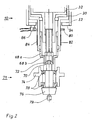
- FIG. 2 shows the lower part of a device 10 for the dynamic screwing of components according to a special embodiment of the invention, which is provided with a component 71 and which is provided with a screwing torque measuring device for measuring the screwing torque directly on a component 71 to be screwed.
- the component 71 is a bearing unit and comprises a drive flange 72, a component outer part 74, a shaft 76 and a bearing 78 in the form of two tapered roller bearings.
- a tip 79 is provided as a counter bearing for the component 71.
- the component 71 to be screwed is transported into the device 10 by means of a tool carrier (not shown) and positioned under a screwing tool inner part 68b.
- the screw torque measuring device comprises at least four strain gauges, of which only two are visible here and are identified by the reference numerals 82 and 84, for measuring the deformation (torsion) of the step 30, and a slip ring 80 rotating coaxially to the step 30 for detecting screw torque measuring signals from the strain gauges and a read head 86 for forwarding and amplifying tightening torque signals.
- the respective tightening torque can be measured directly on component 71.
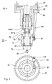
- Fig. 3 shows the lower, i.e. H. Part of a device 10 for the dynamic screwing of components facing a component 71 according to a further particular embodiment of the invention with a bearing friction torque measuring device which is fastened to the slide 42 shown in FIG. 1 via the bearing ring 52.
- the component 71 is constructed exactly as in FIG. 2. Due to the rotary movement, a bearing friction torque is generated by the bearing 78 in the form of two tapered roller bearings, which would cause the component outer part 74 to rotate.
- a support 88 is attached to a flange bore of the component outer part 74 (not marked) by means of a pin 90.
- the support 88 extends obliquely upward from the component outer part 74 to a bearing arm 94 for the bearing ring 52 and is fastened to it in any manner.
- a load cell 92 is integrated in the support 88. The load cell 92 is used to measure the applied support force.
- the bearing friction torque M R results from the product of the tangential force E at the point of articulation of the support 88 on the bearing arm 94 and the radius r, ie the distance between the axis of rotation of the component 71 and the pin 90.
- the arrangement of the support 88 (support) is different Component dependent and can e.g. B. in the form of a pull or push rod. In any case, the support 88 is connected to the component 71 and the bearing ring 52.
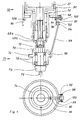
- the bearing friction torque measuring device comprises a support 88, which has one end is fastened by means of a pin 90 to the outer part 74 of the component and is connected with its other end, extending obliquely upwards, by means of two screws 102 and 104 to a ring 96 which extends coaxially to the step 30 and which in turn is connected to a load cell 92 via a holding arm 100 is connected, which in turn is connected to the bearing ring 52 via a holding arm 98.
- the ring 96 is also arranged on the bearing ring 52 by means of a bearing 106.
- the support torque is in turn measured via the load cell 92.
- the support can be adapted to different components more easily than in the embodiment shown in FIG. 3.
Landscapes
- Engineering & Computer Science (AREA)
- Mechanical Engineering (AREA)
- Retarders (AREA)
- Support Of The Bearing (AREA)
- Transmission Devices (AREA)
- Details Of Spanners, Wrenches, And Screw Drivers And Accessories (AREA)
- Sliding-Contact Bearings (AREA)
- Force Measurement Appropriate To Specific Purposes (AREA)
Abstract
Description
Die vorliegende Erfindung betrifft eine Vorrichtung gemäß dem Oberbegriff von Anspruch_1 und ein Verfahren zum dynamischen Verschrauben von Bauteilen, insbesondere von Lagerund Getriebeeinheiten.The present invention relates to a device according to the preamble of claim 1 and a method for the dynamic screwing of components, in particular of bearing and gear units.
Eine Vorrichtung der eingangs genannten Art ist aus der DE 201 10 798 U1 bekannt. Der Verschraubprozeß erfolgt dabei für ein Schraubenverbindungselement (Mutter oder Schraube), das lose angewunden ist, üblicherweise so, daß es bis zur Anlage mit einer fest eingestellten Drehzahl auf- beziehungsweise eingeschraubt wird. Der Endanzug auf das vorgegebene Anziehmoment wird dann mit einer niedrigeren Drehzahl vorgenommen, wobei die Abschaltung des Verschraubantriebes anhand eines von einer zwischengeschalteten Drehmomentmeßwelle gelieferten Signals erfolgt (elektronischer Überlastschutz). Das Umschalten auf die niedrigere Drehzahl wird nach n (fest eingestellt) Umdrehungen vorgenommen. Dieser Verschraubprozeß funktioniert nur dann störungsfrei, wenn
- 1. die freie Aufschraublänge immer gleich ist,
oder - 2. die zu verschraubende Verbindung eine kleine Federrate aufweist und bei Anlage des Schraubenverbindungselements der Verlauf des Drehmoments entsprechend einer bekannten festen Funktion erfolgt und für das Umschalten der Drehzahl genutzt werden kann.
- 1. the free screw-on length is always the same,
or - 2. the connection to be screwed has a low spring rate and when the screw connection element is in contact, the torque takes place according to a known fixed function and can be used for switching the speed.
Diese Voraussetzungen sind häufig nicht gegeben. Dies macht den Verschraubprozeß unsicher.These requirements are often not met. This makes the screwing process unsafe.
Der Erfindung liegt somit die Aufgabe zugrunde, eine Vorrichtung und ein Verfahren zum dynamischen Verschrauben von Bauteilen, insbesondere von Lager- und Getriebeeinheiten, bereitzustellen, mit denen der Verschraubprozeß sicherer wird.The invention is therefore based on the object of providing a device and a method for the dynamic screwing of components, in particular of bearing and gear units, by means of which the screwing process becomes more reliable.
Erfindungsgemäß wird diese Aufgabe bei der gattungsgemäßen Vorrichtung dadurch gelöst, daß beide Planetenträger drehbar gelagert sind und daß eine drehmomentgeschaltete Kopplungseinrichtung zur Kopplung des anderen der beiden Planetenträger mit dem Lagerring sowie eine Detektionseinrichtung zur Detektion einer Drehbewegung des anderen der beiden Planetenträger vorgesehen sind, wobei die Kopplungseinrichtung mit einer ansteuerbaren Festsetzeinrichtung zum Festsetzen des anderen der beiden Planetenträger bei Detektion einer Drehbewegung mit einer Drehgeschwindigkeit oberhalb eines vorab festlegbaren Schwellenwertes durch die Detektionseinrichtung als eine Kombinationseinheit ausgebildet ist. Durch die Kopplungseinrichtung alleine kann der andere der beiden Planetenträger, selbst wenn ein bestimmtes Drehmoment erreicht wird, immer noch durchdrehen, d. h. findet noch kein Festsetzen statt. Erst mit dem Festsetzen durch die Festsetzeinrichtung ist kein Durchdrehen des Planetenträgers mehr möglich. Mit Drehbewegung ist jede Bewegung um einen beliebigen Winkel, das heißt auch weniger als eine Umdrehung, gemeint.According to the invention, this object is achieved in the generic device in that both planet carriers are rotatably mounted and that a torque-switched coupling device for coupling the other of the two planet carriers to the bearing ring and a detection device for detecting a rotational movement of the other of the two planet carriers are provided, the coupling device is designed as a combination unit with a controllable fixing device for fixing the other of the two planet carriers upon detection of a rotational movement with a rotational speed above a predetermined threshold. By means of the coupling device alone, the other of the two planet carriers can still spin, even if a certain torque is reached, i. H. no fixing takes place yet. The planet carrier can no longer be rotated only when it is fixed by the fixing device. Rotary movement means any movement through any angle, that is, less than one revolution.
Weiterhin wird diese Aufgabe gelöst durch ein Verfahren zum dynamischen Verschrauben von Bauteilen, insbesondere von Lager- und Getriebeeinheiten, unter Verwendung der Vorrichtung nach einem der Ansprüche 1 bis 11, gekennzeichnet durch die folgenden Verfahrensschritte: vor Beginn des Verschraubprozesses werden nur die Sonnenraddrehantriebseinrichtung und die drehmomentgeschaltete Kopplungseinrichtung in Betrieb gesetzt oder in Betrieb gehalten, zu Beginn des Verschraubprozesses wird die Planetenträgerdrehantriebseinrichtung mit einer ersten Drehzahl hinzugeschaltet, bei Detektion einer Drehbewegung mit einer Drehgeschwindigkeit oberhalb eines vorgebbaren Schwellenwertes durch die Detektionseinrichtung wird ein Endanzug der Schraubenverbindung bei einer gegenüber der ersten Drehzahl niedrigeren zweiten Drehzahl der Planetenträgerdrehantriebseinrichtung durchgeführt und im wesentlichen gleichzeitig die Festsetzeinrichtung aktiviert und am Ende des Verschraubprozesses wird die Festsetzeinrichtung deaktiviert und im wesentlichen gleichzeitig die Planetenträgerdrehantriebseinrichtung abgeschaltet. Mit Drehbewegung ist jede Bewegung um einen beliebigen Winkel, das heißt auch weniger als eine Umdrehung, gemeint.Furthermore, this object is achieved by a method for the dynamic screwing of components, in particular of bearing and gear units, using the Device according to one of claims 1 to 11, characterized by the following method steps: before the screwing process begins, only the sun gear rotary drive device and the torque-switched coupling device are put into operation or kept in operation; at the start of the screwing process, the planet carrier rotary drive device is switched on at a first speed, upon detection a rotational movement at a rotational speed above a predeterminable threshold value by the detection device, a final tightening of the screw connection is carried out at a lower rotational speed of the planet carrier rotary drive device than the first rotational speed and the fixing device is activated essentially at the same time and at the end of the screwing process the fixing device is deactivated and essentially simultaneously Planet carrier rotary drive device switched off. Rotary movement means any movement through any angle, that is, less than one revolution.
In einer besonderen Ausführungsform der Erfindung weist die Kopplungseinrichtung mindestens ein Reibelement auf.In a special embodiment of the invention, the coupling device has at least one friction element.
Vorteilhafterweise ist/sind das beziehungsweise die Reibelement(e) hinsichtlich der Kopplungskraft wählbar einstellbar.Advantageously, the friction element (s) can be selected with respect to the coupling force.
Vorteilhafterweise ist die Detektionseinrichtung zur berührungslosen Detektion einer Drehbewegung gestaltet.The detection device is advantageously designed for the contactless detection of a rotary movement.
Zweckmäßigerweise weist die Festsetzeinrichtung mindestens ein Bremselement auf.The fixing device expediently has at least one braking element.
Insbesondere ist dabei vorteilhafterweise vorgesehen, daß das beziehungsweise die Reibelement(e) gestaltet ist/sind, um auch als Bremselement beziehungsweise Bremselemente der Festsetzeinrichtung einsetzbar zu sein.In particular, it is advantageously provided that the friction element (s) is / are designed so that they can also be used as a braking element or elements of the fixing device.
Günstigerweise ist eine Schraubmomentmeßeinrichtung zur Messung eines Schraubmoments direkt am zu verschraubenden Bauteil vorgesehen. Dies ist genauer als im Stand der Technik, in dem das Antriebsmoment an der Planetenträgerdrehantriebseinrichtung mit einer Drehmoment-Meßwelle gemessen wird und unter Berücksichtigung eines Übersetzungsverhältnisses und eines Wirkungsgrades des Getriebes umgerechnet wird.A screwing torque measuring device for measuring a screwing torque is advantageously provided directly on the component to be screwed. This is more precise than in the prior art, in which the drive torque on the planet carrier rotary drive device is measured with a torque measuring shaft and is converted taking into account a transmission ratio and an efficiency of the transmission.
Vorteilhafterweise ist eine Lagerreibmomentmeßeinrichtung zur Messung des Reibmomentes der Lagerung des Bauteils vorgesehen, die direkt oder indirekt am Schlitten befestigt ist. Beispielsweise kann die Lagerreibmomentmeßeinrichtung an einem Gehäuse für das Drehzahl-Überlagerungsgetriebe befestigt sein. Dadurch bildet die Lagerreibmomentmeßeinrichtung damit eine Einheit. Es gibt aber auch Anwendungsfälle, wo die Lagerreibmomentmeßeinrichtung nicht am Bauteil befestigt werden kann, sondern sich lediglich an einer Außenkontur des Bauteils abstützt. Im Stand der Technik wird dagegen eine Lagerreibmomentmeßeinrichtung auf einem separaten Schlitten angeordnet und muß sie separat montiert und ausgerichtet werden.A bearing friction torque measuring device for measuring the frictional torque of the bearing of the component is advantageously provided, which is attached directly or indirectly to the slide. For example, the bearing friction torque measuring device can be attached to a housing for the speed superposition gear. As a result, the bearing friction torque measuring device thus forms a unit. But there are also applications where the bearing friction torque measuring device cannot be attached to the component, but is only supported on an outer contour of the component. In the prior art, on the other hand, a bearing friction torque measuring device is arranged on a separate carriage and must be installed and aligned separately.
Eine weitere besondere Ausführungsform der Erfindung zeichnet sich dadurch aus, dass eine Steuereinrichtung vorgesehen ist, die zum Betrieb der Vorrichtung gestaltet ist derart, dass vor Beginn eines Verschraubprozesses nur die Sonnenraddrehantriebseinrichtung und die Kopplungseinrichtung in Betrieb sind, zu Beginn des Verschraubprozesses die Planetenträgerdrehantriebseinrichtung mit einer ersten Drehzahl hinzugeschaltet wird, bei Detektion einer Drehbewegung mit einer Drehgeschwindigkeit oberhalb eines vorgebbaren Schwellenwertes durch die Detektionseinrichtung die Drehzahl der Planetenträgerdrehantriebseinrichtung auf eine gegenüber der ersten Drehzahl niedrigere zweite Drehzahl für den Endanzug des Schraubenverbindungselements abgesenkt und im wesentlichen gleichzeitig die Festsetzeinrichtung aktiviert wird sowie am Ende des Verschraubprozesses die Festsetzeinrichtung deaktiviert und im wesentlichen gleichzeitig die Planetenträgerdrehantriebseinrichtung abgeschaltet wird. Mit Drehbewegung ist jede Bewegung um einen beliebigen Winkel, das heißt auch weniger als eine Umdrehung, gemeint.Another special embodiment of the invention is characterized in that a control device is provided which is designed to operate the device such that only the sun gear rotating drive device and the coupling device are in operation before the start of a screwing process, and the planet carrier rotating drive device with a first one at the beginning of the screwing process Speed is switched on, upon detection of a rotational movement with a rotational speed above a predeterminable threshold value by the detection device, the rotational speed of the planet carrier rotary drive device is reduced to a lower rotational speed than the first rotational speed for the final tightening of the screw connection element and essentially simultaneously the fixing device is activated and at the end of the screwing process the fixing device is deactivated and the planet carrier rotary drive device is switched off essentially simultaneously. Rotary movement means any movement through any angle, that is, less than one revolution.
Beispielsweise kann die Planetenträgerdrehantriebseinrichtung entsprechend einer Stufenfunktion abgeschaltet werden. Die Stufenfunktion kann dabei eine oder mehrere Stufen umfassen. Es ist auch denkbar, dass die Planetenträgerdrehantriebseinrichtung zunächst einmal auf eine geringere Geschwindigkeit geschaltet und dann ganz abgeschaltet wird.For example, the planet carrier rotary drive device can be switched off in accordance with a step function. The step function can include one or more steps. It is also conceivable that the planet carrier rotary drive device is first switched to a lower speed and then switched off completely.
Gemäß einer weiteren besonderen Ausführungsform der Erfindung kann vorgesehen sein, dass die Planetenträgerdrehantriebseinrichtung entsprechend einer stetigen Funktion abgeschaltet wird. Beispielsweise kann die Planetenträgerdrehantriebseinrichtung entsprechend einer linearen oder Exponentialfunktion auf Null geregelt werden.According to a further special embodiment of the invention it can be provided that the planet carrier rotary drive device is switched off in accordance with a continuous function. For example, the planet carrier rotary drive device can be regulated to zero in accordance with a linear or exponential function.
Auch kann bei dem Verfahren vorgesehen sein, dass die Planetenträgerdrehantriebseinrichtung entsprechend einer Stufenfunktion abgeschaltet wird.It can also be provided in the method that the planet carrier rotary drive device is switched off in accordance with a step function.
Andererseits ist auch denkbar, dass die Planetenträgerdrehantriebseinrichtung entsprechend einer stetigen Funktion abgeschaltet wird.On the other hand, it is also conceivable that the planet carrier rotary drive device is switched off in accordance with a continuous function.
Ferner kann bei dem Verfahren vorgesehen sein, dass am Ende des Verschraubprozesses die Festsetzeinrichtung nach einer vorgebbaren Zeit oder bei Erreichen eines bestimmten Anziehmoments deaktiviert wird.Furthermore, it can be provided in the method that, at the end of the screwing process, the fixing device is deactivated after a predeterminable time or when a specific tightening torque is reached.
Günstigerweise wird ein Schraubmoment direkt am zu verschraubenden Bauteil gemessen.A tightening torque is advantageously measured directly on the component to be screwed.
Ebenfalls zweckmäßigerweise wird ein Lagerreibmoment mittels einer direkt oder indirekt befestigten Lagerreibmomentmeßeinrichtung gemessen.A bearing friction torque is also expediently measured by means of a directly or indirectly attached bearing friction torque measuring device.
Vorteilhafterweise wird das Verfahren automatisch ausgeführt.The method is advantageously carried out automatically.
Der Erfindung liegt die überraschende Erkenntnis zugrunde, daß der Verschraubprozeß sicherer wird, indem zwischen dem anfänglichen Anschrauben mit einer ersten Drehzahl und dem Endanzug mit einer gegenüber der ersten Drehzahl niedrigeren zweiten Drehzahl ein temporäres Sicherheitskuppeln vorgesehen ist. Darüber hinaus lassen sich dadurch auch die Bauteile vor Beschädigung und die Antriebseinrichtungen vor Überlast oder sogar Zerstörung schützen.The invention is based on the surprising finding that the screwing process is made more secure by providing a temporary safety coupling between the initial screwing on at a first speed and the end suit with a second speed that is lower than the first speed. In addition, the components can be protected against damage and the drive devices against overload or even destruction.
Ferner bietet der erfindungsgemäße mechanische Überlastschutz den Vorteil, daß durch die möglichen hohen Anfangsschraubgeschwindigkeiten höhere Schraubraten möglich sind. Der mechanische Überlastschutz bietet gegenüber einem elektronischen Überlastschutz zudem eine einfachere Regelung des Verschraubprozesses.Furthermore, the mechanical overload protection according to the invention has the advantage that higher screwing rates are possible due to the possible high initial screwing speeds. The mechanical overload protection also offers a simpler control of the screwing process compared to electronic overload protection.
Weitere Merkmale und Vorteile der Erfindung ergeben sich aus den Ansprüchen und aus der nachstehenden Beschreibung, in der Ausführungsbeispiele anhand der schematischen Zeichnungen im einzelnen erläutert sind. Dabei zeigt:
- Fig. 1 eine Vertikalschnittansicht eines Teils einer Vorrichtung gemäß einer besonderen Ausführungsform der vorliegenden Erfindung;
- Fig. 2 eine Vertikalschnittansicht eines unteren Teils einer Vorrichtung gemäß einer weiteren besonderen Ausführungsform der vorliegenden Erfindung;
- Fig. 3 eine Vertikalschnittansicht (oben) und eine Draufsicht (unten) eines unteren Teils einer Vorrichtung gemäß einer weiteren besonderen Ausführungsform der vorliegenden Erfindung; und
- Fig. 4 eine Vertikalschnittansicht (oben) und eine Draufsicht (unten) eines unteren Teils einer Vorrichtung gemäß einer weiteren besonderen Ausführungsform der vorliegenden Erfindung.
- 1 is a vertical sectional view of part of a device according to a particular embodiment of the present invention;
- 2 is a vertical sectional view of a lower part of a device according to a further particular embodiment of the present invention;
- 3 shows a vertical sectional view (top) and a top view (bottom) of a lower part of a device according to a further particular embodiment of the present invention; and
- Fig. 4 is a vertical sectional view (above) and a plan view (below) of a lower part of a device according to another particular embodiment of the present invention.
Die in Fig. 1 gezeigte Vorrichtung 10 weist ein Drehzahl-Überlagerungsgetriebe 22 auf, das aus zwei hintereinander angeordneten Planetengetrieben 24 und 26 mit einem gemeinsamen Sonnenrad 28 und zueinander koaxialen Abtrieben in Form von Stegrädern 30 und 32 besteht. Jedes der Planetengetriebe 24 und 26 weist drei Planetenräder auf, von denen lediglich die Planetenräder 34 und 36 sowie 38 und 40 zu sehen sind. Jedes der Planetengetriebe 24 und 26 weist zudem einen drehbar gelagerten Planetenträger 24a beziehungsweise 26a auf. Das Sonnenrad 28 ist über eine ansteuerbare Sonnenraddrehantriebseinrichtung (nicht gezeigt) und der Planetenträger 26a ist über eine ansteuerbaren Planetenträgerdrehantriebseinrichtung (nicht gezeigt) antreibbar. Die Sonnenraddrehantriebseinrichtung, die Planetenträgerdrehantriebseinrichtung und das Drehzahl-Überlagerungsgetriebe 22 sind auf einem verfahrbaren Schlitten 42 angeordnet.The
Weiterhin weist die Vorrichtung 10 eine drehmomentgeschaltete Kopplungseinrichtung zur Kopplung des Planetenträgers 24a mit einem Lagerring 52 auf. Besagte Kopplungseinrichtung weist eine Scheibe 50 aus gehärtetem Stahl als Reibelement auf, die zwischen dem Planetenträger 24a und dem Lagerring 52 angeordnet ist. Das Reibmoment wird durch Andruck der Scheibe 50 zwischen dem Planetenträger 24a und dem Lagerring 52 erzeugt. Die erforderliche Druckkraft wird von einer Wippe 54 auf einen Druckring 56 übertragen, der über ein Spannelement 58, das bei geringer Kraft als Feder wirkt, die Kraft auf die Scheibe 50 überträgt. Die Wippe 54 wird mittels einer Vorspannmutter 60 eingestellt. Die Lagerung der Wippe 54 ist nicht gezeigt.Furthermore, the
Die Kopplungseinrichtung dient gleichzeitig als ansteuerbare Festsetzeinrichtung zum Festsetzen des Planetenträgers 24a. Dazu umfaßt sie einen Pneumatikzylinder 62. Über den Pneumatikzylinder 62 wird eine Spannkraft erzeugt und durch das Übersetzungsverhältnis der Wippe 54 auf die erforderliche Betätigungskraft des Spannelements 58 erhöht. Besagtes Spannelement 58 verbindet kraftschlüssig den Lagerring 52 mit dem Planetenträger 24a.The coupling device also serves as a controllable fixing device for fixing the planet carrier 24a. For this purpose, it comprises a
In der hier dargestellten Ausführungsform besteht somit die Kopplungseinrichtung aus der Scheibe 50, dem Druckring 56, dem Spannelement 58 und der Wippe 54, wobei das Spannelement 58 gleichzeitig zur Festsetzeinrichtung gehört.In the embodiment shown here, the coupling device thus consists of the
Die Vorrichtung umfaßt außerdem eine Detektionseinrichtung zur Detektion einer Drehbewegung des Planetenträgers 24a. Dazu umfaßt die Detektionseinrichtung eine Zahnscheibe 64 am Planetenträger 24a und einen Sensor 66 zur Erfassung der Drehbewegung.The device also includes a detection device for detecting a rotational movement of the planet carrier 24a. For this purpose, the detection device comprises a
Die oben beschriebene Vorrichtung läßt sich mittels einer Steuereinrichtung (nicht gezeigt) wie folgt betreiben:
- Vor Beginn eines Verschraubprozesses sind nur die Sonnenraddrehantriebseinrichtung und die Einrichtung zur Bildung einer drehmomentgeschalteten Kupplung in Betrieb. Dadurch dreht sich
das Sonnenrad 28 bei ruhendem Planetenträger 26a und gebremstem Planetenträger 24a und laufen dieStegräder 30 und 32 synchron, d. h., dass keine Schraubbewegung zum Verschrauben der Bauteile stattfindet.
- Before the start of a screwing process, only the sun gear rotary drive device and the device for forming a torque-switched clutch are in operation. As a result, the
sun gear 28 rotates when theplanet carrier 26a is at rest and the planet carrier 24a is braked, and the planet gears 30 and 32 run synchronously, ie there is no screwing movement for screwing the components together.
Zu Beginn des Verschraubprozesses wird die Planetenträgerdrehantriebseinrichtung mit einer ersten Drehzahl in gleichem oder entgegengesetzten Drehsinn bzgl. der Sonnenraddrehantriebseinrichtung hinzugeschaltet. Dadurch dreht sich dann auch der Planetenträger 26a, während der Planetenträger 24a weiterhin gebremst bleibt. Dies hat zur Folge, dass die Stegräder 30 und 32 nicht mehr synchron laufen und somit eine Schraubbewegung, d. h. ein Schraubmoment zum Verschrauben der Bauteile entsteht. Bei Erreichen eines Haltemomentes blockiert das Stegrad 30. Es erfolgt somit keine Schraubbewegung mehr. Dies bedeutet nichts anderes, dass das Stegrad 30 von dem Stegrad 32 wieder zum Synchronlaufen gezwungen wird, wodurch eine Reaktion über die Planetenräder 34 und 36 auf den Planetenträger 24a in der Form erfolgt, daß der Planetenträger 24a in der von der Einrichtung zur Bildung einer drehmomentgeschalteten Kupplung gebildeten Rutschkupplung durchrutscht. Dies bedeutet, daß der Planetenträger 24a eine Drehbewegung durchführt. Letztere wird wiederum von dem Sensor 66 erfaßt. Der Sensor 66 liefert ein entsprechendes Signal an die Steuereinrichtung, die daraufhin die Drehzahl der Planetenträgerdrehantriebseinrichtung auf eine niedrigere zweite Drehzahl für den Endanzug des Schraubenverbindungselements absenkt und im wesentlichen gleichzeitig die Festsetzeinrichtung aktiviert, das heißt das Spannelement 58 verbindet den Lagerring 52 und den Planetenträger 24a kraftschlüssig. Das Spannelement 58 übt beim Flachdrücken sehr große Radialkräfte auf den Innen- und Außendurchmesser aus. Bei niedrigem Reibmoment wirkt das Spannelement 58 als Tellerfeder und drückt die Scheibe 50 gegen die Fläche an dem Planetenträger 24a. Es kann dann das volle Schraubmoment für den Endanzug übertragen werden. Der Endanzug wird dabei grundsätzlich entweder nach dem Anziehmoment oder nach dem Reibmoment der Lagerung begrenzt. Die dazu erforderlichen Meßeinrichtungen werden von der Steuereinrichtung ausgewertet. Am Ende des Verschraubprozesses wird die Festsetzeinrichtung deaktiviert und im wesentlichen gleichzeitig die Planetenträgerdrehantriebseinrichtung abgeschaltet.At the beginning of the screwing process, the planet carrier rotary drive device is switched on at a first speed in the same or opposite direction of rotation with respect to the sun wheel rotary drive device. As a result, the
Fig. 2 zeigt den unteren, d. h. zu einem Bauteil 71 gewandten Teil einer Vorrichtung 10 zum dynamischen Verschrauben von Bauteilen gemäß einer besonderen Ausführungsform der Erfindung, die mit einer Schraubmomentmeßeinrichtung zum Messen des Schraubmoments direkt an einem zu verschraubenden Bauteil 71 versehen ist. Das Bauteil 71 ist eine Lagereinheit und umfasst einen Antriebsflansch 72, ein Bauteil-Außenteil 74, eine Welle 76 und eine Lagerung 78 in Form von zwei Kegelrollenlagern. Eine Spitze 79 ist als Gegenlager für das Bauteil 71 vorgesehen. Das zu verschraubende Bauteil 71 wird mittels eines Werkzeugträgers (nicht gezeigt) in die Vorrichtung 10 transportiert und unter ein Schraubwerkzeug-Innenteil 68b positioniert. Der in Fig. 1 gezeigte Schlitten 42 senkt ab und das Schraubwerkzeug-Innenteil 68b (Abtrieb des Planetengetriebes 26) setzt auf ein Schraubenelement, hier Bundmutter 70 auf, während ein mit dem Stegrad 30 in Verbindung stehendes Schraubwerkzeug-Außenteil 68a auf den Antriebsflansch 72 aufsetzt und eine drehfeste Verbindung mit diesem herstellt.2 shows the lower part of a
Die Schraubmomentmeßeinrichtung umfasst mindestens vier Dehnungsmeßstreifen, von denen hier nur zwei sichtbar und mit den Bezugszeichen 82 und 84 gekennzeichnet sind, zur Messung der Verformung (Torsion) des Stegrades 30 sowie einen koaxial zum Stegrad 30 umlaufenden Schleifring 80 zur Erfassung von Schraubmomentmeßsignalen von den Dehnungsmeßstreifen und einen Lesekopf 86 zur Weiterleitung und Verstärkung von Schraubmomentmeßsignalen. Dadurch kann das jeweilige Schraubmoment direkt am Bauteil 71 gemessen werden.The screw torque measuring device comprises at least four strain gauges, of which only two are visible here and are identified by the
Fig. 3 zeigt den unteren, d. h. zu einem Bauteil 71 gewandten Teil einer Vorrichtung 10 zum dynamischen Verschrauben von Bauteilen gemäß einer weiteren besonderen Ausführungsform der Erfindung mit einer Lagerreibmomentmeßeinrichtung, die am in Fig. 1 gezeigten Schlitten 42 über den Lagerring 52 befestigt ist.Fig. 3 shows the lower, i.e. H. Part of a
Das Bauteil 71 ist genau wie in Fig. 2 aufgebaut. Durch die Drehbewegung wird von der Lagerung 78 in Form von zwei Kegelrollenlagern ein Lagerreibmoment erzeugt, dass das Bauteil-Außenteil 74 in Rotation versetzen würde. Um dies zu verhindern, ist in eine nicht gekennzeichnete Flanschbohrung des Bauteil-Außenteils 74 mittels eines Stiftes 90 eine Stütze 88 angebracht. Die Stütze 88 erstreckt sich vom Bauteil-Außenteil 74 schräg nach oben zu einem Lagerarm 94 für den Lagerring 52 und ist daran auf beliebige Weise befestigt. Wie sich aus der unteren Zeichnung in Fig. 3 ergibt, ist in der Stütze 88 eine Kraftmeßdose 92 integriert. Die Kraftmeßdose 92 dient zur Messung der anliegenden Abstützkraft. Das Lagerreibmoment MR ergibt sich aus dem Produkt der Tangentialkraft E am Anlenkpunkt der Stütze 88 am Lagerarm 94 und dem Radius r, d. h. der Entfernung zwischen der Drehachse des Bauteils 71 und dem Stift 90. Die Anordnung der Stütze 88 (Abstützung) ist vom jeweiligen Bauteil abhängig und kann z. B. in Form einer Zug- bzw. Druckstange ausgeführt sein. In jedem Fall ist die Stütze 88 mit dem Bauteil 71 und dem Lagerring 52 verbunden.The
In Fig. 4 ist eine Variante der in Fig. 3 gezeigten Lagerreibmomentmeßeinrichtung gezeigt. Die Lagerreibmomentmeßeinrichtung umfasst eine Stütze 88, die mit ihrem einen Ende mittels eines Stiftes 90 am Bauteil-Außenteil 74 befestigt ist und sich nach schräg nach oben erstreckend mit ihrem anderen Ende mittels zweier Schrauben 102 und 104 an einem koaxial zum Stegrad 30 umlaufenden Ring 96 verbunden ist, der wiederum über einen Haltearm 100 mit einer Kraftmeßdose 92 verbunden ist, die wiederum über einen Haltearm 98 mit dem Lagerring 52 verbunden ist. Der Ring 96 ist darüber hinaus am Lagerring 52 mittels einer Lagerung 106 angeordnet. Über die Kraftmeßdose 92 wird wiederum das Abstützmoment gemessen. Bei dieser Variante einer Lagerreibmomentmeßeinrichtung kann die Abstützung leichter als bei der Fig. 3 gezeigten Ausführung an unterschiedliche Bauteile angepasst werden.4 shows a variant of the bearing friction torque measuring device shown in FIG. 3. The bearing friction torque measuring device comprises a
Die in der vorliegenden Beschreibung, in den Zeichnungen sowie in den Ansprüchen offenbarten Merkmale der Erfindung können sowohl einzeln als auch in beliebigen Kombinationen für die Verwirklichung der Erfindung in ihren verschiedenen Ausführungsformen wesentlich sein.The features of the invention disclosed in the present description, in the drawings and in the claims can be essential both individually and in any combination for realizing the invention in its various embodiments.
- 1010
- Vorrichtungcontraption
- 2222
- Drehzahl-ÜberlagerungsgetriebeSpeed modulation gear
- 24, 2624, 26
- Planetengetriebeplanetary gear
- 24a24a
- Planetenträgerplanet carrier
- 26a26a
- Planetenträgerplanet carrier
- 2828
- Sonnenradsun
- 30, 3230, 32
- StegräderSteg wheels
- 34, 36, 38, 4034, 36, 38, 40
- Planetenräderplanetary gears
- 4242
- Schlittencarriage
- 5050
- Scheibedisc
- 5252
- Lagerringbearing ring
- 5454
- Wippeseesaw
- 5656
- Druckringpressure ring
- 5858
- Spannelementclamping element
- 6060
- Vorspannmutterpreload nut
- 6262
- Pneumatikzylinderpneumatic cylinder
- 6464
- Zahnscheibetoothed washer
- 6666
- Sensorsensor
- 68a68a
- Schraubwerkzeug-AußenteilWrench outer part
- 68b68b
- Schraubwerkzeug-InnenteilWrench inner part
- 7070
- BundmutterBundmutter
- 7171
- Bauteilcomponent
- 7272
- Antriebsflanschdrive flange
- 7474
- Bauteil-AußenteilComponent outer part
- 7676
- Wellewave
- 7878
- Lagerungstorage
- 7979
- Spitzetop
- 8080
- Schleifringslip ring
- 82, 8482, 84
- Dehnungsmeßstreifenstrain
- 8686
- Lesekopfread head
- 8888
- Stützesupport
- 9090
- Stiftpen
- 9292
- Kraftmeßdoseload cell
- 9494
- Lagerarmbearing arm
- 9696
- Ringring
- 9898
- Haltearmholding arm
- 100100
- Haltearmholding arm
- 102, 104102, 104
- Schraubenscrew
- 106106
- Lagerungstorage
Claims (18)
dadurch gekennzeichnet,
daß beide Planetenträger (24a, 26a) drehbar gelagert sind und dass
eine drehmomentgeschaltete Kopplungseinrichtung zur Kopplung des anderen (24a oder 26a) der beiden Planetenträger mit dem Lagerring (52) sowie eine Detektionseinrichtung zur Detektion einer Drehbewegung des anderen (24a oder 26a) der beiden Planetenträger vorgesehen sind, wobei die Kopplungseinrichtung mit einer ansteuerbaren Festsetzeinrichtung zum Festsetzen des anderen (24a oder 26a) der beiden Planetenträger bei Detektion einer Drehbewegung mit einer Drehgeschwindigkeit oberhalb eines vorab festlegbaren Schwellenwertes durch die Detektionseinrichtung als eine Kombinationseinheit ausgebildet ist.Device (10) for the dynamic screwing of components, in particular of bearing and gear units, with a speed superposition gear (22) for rotating a screw connecting element and a part of a component with different speeds to be screwed therewith, the two planetary gear (24, 26 ) with a respective planet carrier (24a, 26a) and respective planet gears (34, 36; 38 40) and with a common sun gear (28), a controllable sun gear rotary drive device and a controllable planet carrier rotary drive device for rotating one of the two planet carriers (24a or 26a) , the sun gear rotary drive device, the planet carrier rotary drive device and the speed superposition gear (22) being arranged on a movable carriage (42) with a bearing ring (52),
characterized,
that both planet carriers (24a, 26a) are rotatably mounted and that
a torque-switched coupling device for coupling the other (24a or 26a) of the two planet carriers to the bearing ring (52) and a detection device for detecting a rotational movement of the other (24a or 26a) of the two planet carriers are provided, the coupling device having a controllable fixing device for fixing the other (24a or 26a) of the two planet carriers is designed as a combination unit upon detection of a rotational movement at a rotational speed above a predetermined threshold by the detection device.
Applications Claiming Priority (2)
| Application Number | Priority Date | Filing Date | Title |
|---|---|---|---|
| DE10328983 | 2003-06-27 | ||
| DE10328983A DE10328983B4 (en) | 2003-06-27 | 2003-06-27 | Device for the dynamic screwing of components, in particular of bearing and gear units |
Publications (3)
| Publication Number | Publication Date |
|---|---|
| EP1491285A2 true EP1491285A2 (en) | 2004-12-29 |
| EP1491285A3 EP1491285A3 (en) | 2007-11-21 |
| EP1491285B1 EP1491285B1 (en) | 2008-11-05 |
Family
ID=33395014
Family Applications (1)
| Application Number | Title | Priority Date | Filing Date |
|---|---|---|---|
| EP04014931A Expired - Lifetime EP1491285B1 (en) | 2003-06-27 | 2004-06-25 | Device and method for dynamically screwing components, in particular for bearing and transmission assemblies |
Country Status (3)
| Country | Link |
|---|---|
| EP (1) | EP1491285B1 (en) |
| AT (1) | ATE413254T1 (en) |
| DE (2) | DE10328983B4 (en) |
Families Citing this family (1)
| Publication number | Priority date | Publication date | Assignee | Title |
|---|---|---|---|---|
| CN111945625B (en) * | 2020-08-20 | 2022-02-25 | 陈荣才 | Auxiliary device is demolishd to municipal administration facility |
Family Cites Families (3)
| Publication number | Priority date | Publication date | Assignee | Title |
|---|---|---|---|---|
| US3596718A (en) * | 1969-07-02 | 1971-08-03 | Gardner Denver Co | Torque control system |
| DE4307131C2 (en) * | 1993-03-06 | 1995-11-16 | Albert Kipfelsberger | Power wrench with electronic torque limitation |
| DE20110798U1 (en) * | 2001-06-29 | 2002-01-31 | Klimas, Joachim, 86316 Friedberg | Device for the dynamic screwing of components, in particular bearing and gear units |
-
2003
- 2003-06-27 DE DE10328983A patent/DE10328983B4/en not_active Expired - Fee Related
-
2004
- 2004-06-25 DE DE502004008381T patent/DE502004008381D1/en not_active Expired - Lifetime
- 2004-06-25 EP EP04014931A patent/EP1491285B1/en not_active Expired - Lifetime
- 2004-06-25 AT AT04014931T patent/ATE413254T1/en active
Also Published As
| Publication number | Publication date |
|---|---|
| DE502004008381D1 (en) | 2008-12-18 |
| DE10328983A1 (en) | 2005-01-27 |
| DE10328983B4 (en) | 2005-11-24 |
| ATE413254T1 (en) | 2008-11-15 |
| EP1491285A3 (en) | 2007-11-21 |
| EP1491285B1 (en) | 2008-11-05 |
Similar Documents
| Publication | Publication Date | Title |
|---|---|---|
| DE69814439T2 (en) | MODULAR ACTUATING DEVICE AND CALIPER WITH SUCH AN ACTUATING DEVICE | |
| EP1579124B1 (en) | Electromechanically-operated parking brake | |
| DE10392252B4 (en) | disc brake | |
| EP0784162B1 (en) | Brake pad wear indicator | |
| DE19629168C1 (en) | Wind turbine with tower, gondola, and brake | |
| DE19611911A1 (en) | Braking device | |
| DE3629453C2 (en) | ||
| EP1194709A1 (en) | Friction-wheel planetary gear with bevel gears | |
| EP0239830B1 (en) | Device for adjusting the relative rotational position between a toothed wheel and a coaxal toothed crown | |
| DE19510717C2 (en) | Electric steering device for industrial trucks | |
| DE9313282U1 (en) | Axial thread rolling head | |
| DE19605988A1 (en) | Device for actuating a wheel brake of a vehicle | |
| EP1754566A1 (en) | Turntable with stepping drive | |
| DE102009032808B4 (en) | Device for measuring an imbalance of a vehicle wheel | |
| EP0077890B1 (en) | Electric chain hoist | |
| DE69102746T2 (en) | Electromechanical control using a centrifuge. | |
| EP3847123B1 (en) | Crane and method for weathervaning such a crane | |
| EP1491285B1 (en) | Device and method for dynamically screwing components, in particular for bearing and transmission assemblies | |
| EP0094377B1 (en) | Device for quickly adjusting the reciprocal position of two parts, especially for office furniture | |
| EP0771648A1 (en) | Device for taking up backlash in a printing machine | |
| WO2022017553A1 (en) | Method for setting an axial preload force of a roller screw drive of an actuator of a steering device of a motor vehicle | |
| DE3606039C2 (en) | ||
| EP1931957B1 (en) | Method and device for testing the braking action of a motor vehicle having at least two driven axles | |
| DE102018113697A1 (en) | Device and method for adjustable, synchronous power transmission to at least two traction means | |
| DE102006029943A1 (en) | Self-energizing disc brake and method of driving it |
Legal Events
| Date | Code | Title | Description |
|---|---|---|---|
| PUAI | Public reference made under article 153(3) epc to a published international application that has entered the european phase |
Free format text: ORIGINAL CODE: 0009012 |
|
| AK | Designated contracting states |
Kind code of ref document: A2 Designated state(s): AT BE BG CH CY CZ DE DK EE ES FI FR GB GR HU IE IT LI LU MC NL PL PT RO SE SI SK TR |
|
| AX | Request for extension of the european patent |
Extension state: AL HR LT LV MK |
|
| PUAL | Search report despatched |
Free format text: ORIGINAL CODE: 0009013 |
|
| AK | Designated contracting states |
Kind code of ref document: A3 Designated state(s): AT BE BG CH CY CZ DE DK EE ES FI FR GB GR HU IE IT LI LU MC NL PL PT RO SE SI SK TR |
|
| AX | Request for extension of the european patent |
Extension state: AL HR LT LV MK |
|
| 17P | Request for examination filed |
Effective date: 20080424 |
|
| GRAP | Despatch of communication of intention to grant a patent |
Free format text: ORIGINAL CODE: EPIDOSNIGR1 |
|
| AKX | Designation fees paid |
Designated state(s): AT BE BG CH CY CZ DE DK EE ES FI FR GB GR HU IE IT LI LU MC NL PL PT RO SE SI SK TR |
|
| GRAS | Grant fee paid |
Free format text: ORIGINAL CODE: EPIDOSNIGR3 |
|
| GRAA | (expected) grant |
Free format text: ORIGINAL CODE: 0009210 |
|
| AK | Designated contracting states |
Kind code of ref document: B1 Designated state(s): AT BE BG CH CY CZ DE DK EE ES FI FR GB GR HU IE IT LI LU MC NL PL PT RO SE SI SK TR |
|
| REG | Reference to a national code |
Ref country code: GB Ref legal event code: FG4D Free format text: NOT ENGLISH |
|
| REG | Reference to a national code |
Ref country code: CH Ref legal event code: EP |
|
| REG | Reference to a national code |
Ref country code: IE Ref legal event code: FG4D Free format text: LANGUAGE OF EP DOCUMENT: GERMAN |
|
| REF | Corresponds to: |
Ref document number: 502004008381 Country of ref document: DE Date of ref document: 20081218 Kind code of ref document: P |
|
| NLV1 | Nl: lapsed or annulled due to failure to fulfill the requirements of art. 29p and 29m of the patents act | ||
| PG25 | Lapsed in a contracting state [announced via postgrant information from national office to epo] |
Ref country code: ES Free format text: LAPSE BECAUSE OF FAILURE TO SUBMIT A TRANSLATION OF THE DESCRIPTION OR TO PAY THE FEE WITHIN THE PRESCRIBED TIME-LIMIT Effective date: 20090216 |
|
| PG25 | Lapsed in a contracting state [announced via postgrant information from national office to epo] |
Ref country code: PL Free format text: LAPSE BECAUSE OF FAILURE TO SUBMIT A TRANSLATION OF THE DESCRIPTION OR TO PAY THE FEE WITHIN THE PRESCRIBED TIME-LIMIT Effective date: 20081105 Ref country code: SI Free format text: LAPSE BECAUSE OF FAILURE TO SUBMIT A TRANSLATION OF THE DESCRIPTION OR TO PAY THE FEE WITHIN THE PRESCRIBED TIME-LIMIT Effective date: 20081105 Ref country code: FI Free format text: LAPSE BECAUSE OF FAILURE TO SUBMIT A TRANSLATION OF THE DESCRIPTION OR TO PAY THE FEE WITHIN THE PRESCRIBED TIME-LIMIT Effective date: 20081105 Ref country code: NL Free format text: LAPSE BECAUSE OF FAILURE TO SUBMIT A TRANSLATION OF THE DESCRIPTION OR TO PAY THE FEE WITHIN THE PRESCRIBED TIME-LIMIT Effective date: 20081105 |
|
| REG | Reference to a national code |
Ref country code: IE Ref legal event code: FD4D |
|
| PG25 | Lapsed in a contracting state [announced via postgrant information from national office to epo] |
Ref country code: RO Free format text: LAPSE BECAUSE OF FAILURE TO SUBMIT A TRANSLATION OF THE DESCRIPTION OR TO PAY THE FEE WITHIN THE PRESCRIBED TIME-LIMIT Effective date: 20081105 Ref country code: DK Free format text: LAPSE BECAUSE OF FAILURE TO SUBMIT A TRANSLATION OF THE DESCRIPTION OR TO PAY THE FEE WITHIN THE PRESCRIBED TIME-LIMIT Effective date: 20081105 Ref country code: IE Free format text: LAPSE BECAUSE OF FAILURE TO SUBMIT A TRANSLATION OF THE DESCRIPTION OR TO PAY THE FEE WITHIN THE PRESCRIBED TIME-LIMIT Effective date: 20081105 Ref country code: BG Free format text: LAPSE BECAUSE OF FAILURE TO SUBMIT A TRANSLATION OF THE DESCRIPTION OR TO PAY THE FEE WITHIN THE PRESCRIBED TIME-LIMIT Effective date: 20090205 Ref country code: EE Free format text: LAPSE BECAUSE OF FAILURE TO SUBMIT A TRANSLATION OF THE DESCRIPTION OR TO PAY THE FEE WITHIN THE PRESCRIBED TIME-LIMIT Effective date: 20081105 |
|
| PG25 | Lapsed in a contracting state [announced via postgrant information from national office to epo] |
Ref country code: CZ Free format text: LAPSE BECAUSE OF FAILURE TO SUBMIT A TRANSLATION OF THE DESCRIPTION OR TO PAY THE FEE WITHIN THE PRESCRIBED TIME-LIMIT Effective date: 20081105 Ref country code: PT Free format text: LAPSE BECAUSE OF FAILURE TO SUBMIT A TRANSLATION OF THE DESCRIPTION OR TO PAY THE FEE WITHIN THE PRESCRIBED TIME-LIMIT Effective date: 20090406 Ref country code: SE Free format text: LAPSE BECAUSE OF FAILURE TO SUBMIT A TRANSLATION OF THE DESCRIPTION OR TO PAY THE FEE WITHIN THE PRESCRIBED TIME-LIMIT Effective date: 20090205 |
|
| PLBE | No opposition filed within time limit |
Free format text: ORIGINAL CODE: 0009261 |
|
| STAA | Information on the status of an ep patent application or granted ep patent |
Free format text: STATUS: NO OPPOSITION FILED WITHIN TIME LIMIT |
|
| PG25 | Lapsed in a contracting state [announced via postgrant information from national office to epo] |
Ref country code: SK Free format text: LAPSE BECAUSE OF FAILURE TO SUBMIT A TRANSLATION OF THE DESCRIPTION OR TO PAY THE FEE WITHIN THE PRESCRIBED TIME-LIMIT Effective date: 20081105 |
|
| 26N | No opposition filed |
Effective date: 20090806 |
|
| BERE | Be: lapsed |
Owner name: KLIMAS, JOACHIM Effective date: 20090630 |
|
| PG25 | Lapsed in a contracting state [announced via postgrant information from national office to epo] |
Ref country code: MC Free format text: LAPSE BECAUSE OF NON-PAYMENT OF DUE FEES Effective date: 20090630 |
|
| REG | Reference to a national code |
Ref country code: CH Ref legal event code: PL |
|
| GBPC | Gb: european patent ceased through non-payment of renewal fee |
Effective date: 20090625 |
|
| REG | Reference to a national code |
Ref country code: FR Ref legal event code: ST Effective date: 20100226 |
|
| PG25 | Lapsed in a contracting state [announced via postgrant information from national office to epo] |
Ref country code: CH Free format text: LAPSE BECAUSE OF NON-PAYMENT OF DUE FEES Effective date: 20090630 Ref country code: LI Free format text: LAPSE BECAUSE OF NON-PAYMENT OF DUE FEES Effective date: 20090630 Ref country code: FR Free format text: LAPSE BECAUSE OF NON-PAYMENT OF DUE FEES Effective date: 20090630 |
|
| PG25 | Lapsed in a contracting state [announced via postgrant information from national office to epo] |
Ref country code: GB Free format text: LAPSE BECAUSE OF NON-PAYMENT OF DUE FEES Effective date: 20090625 |
|
| PG25 | Lapsed in a contracting state [announced via postgrant information from national office to epo] |
Ref country code: BE Free format text: LAPSE BECAUSE OF NON-PAYMENT OF DUE FEES Effective date: 20090630 |
|
| PG25 | Lapsed in a contracting state [announced via postgrant information from national office to epo] |
Ref country code: GR Free format text: LAPSE BECAUSE OF FAILURE TO SUBMIT A TRANSLATION OF THE DESCRIPTION OR TO PAY THE FEE WITHIN THE PRESCRIBED TIME-LIMIT Effective date: 20090206 |
|
| PG25 | Lapsed in a contracting state [announced via postgrant information from national office to epo] |
Ref country code: LU Free format text: LAPSE BECAUSE OF NON-PAYMENT OF DUE FEES Effective date: 20090625 |
|
| PG25 | Lapsed in a contracting state [announced via postgrant information from national office to epo] |
Ref country code: HU Free format text: LAPSE BECAUSE OF FAILURE TO SUBMIT A TRANSLATION OF THE DESCRIPTION OR TO PAY THE FEE WITHIN THE PRESCRIBED TIME-LIMIT Effective date: 20090506 |
|
| PG25 | Lapsed in a contracting state [announced via postgrant information from national office to epo] |
Ref country code: TR Free format text: LAPSE BECAUSE OF FAILURE TO SUBMIT A TRANSLATION OF THE DESCRIPTION OR TO PAY THE FEE WITHIN THE PRESCRIBED TIME-LIMIT Effective date: 20081105 |
|
| PG25 | Lapsed in a contracting state [announced via postgrant information from national office to epo] |
Ref country code: CY Free format text: LAPSE BECAUSE OF FAILURE TO SUBMIT A TRANSLATION OF THE DESCRIPTION OR TO PAY THE FEE WITHIN THE PRESCRIBED TIME-LIMIT Effective date: 20081105 |
|
| PGFP | Annual fee paid to national office [announced via postgrant information from national office to epo] |
Ref country code: AT Payment date: 20120529 Year of fee payment: 9 |
|
| PGFP | Annual fee paid to national office [announced via postgrant information from national office to epo] |
Ref country code: DE Payment date: 20130627 Year of fee payment: 10 |
|
| PGFP | Annual fee paid to national office [announced via postgrant information from national office to epo] |
Ref country code: IT Payment date: 20130620 Year of fee payment: 10 |
|
| REG | Reference to a national code |
Ref country code: DE Ref legal event code: R119 Ref document number: 502004008381 Country of ref document: DE |
|
| REG | Reference to a national code |
Ref country code: AT Ref legal event code: MM01 Ref document number: 413254 Country of ref document: AT Kind code of ref document: T Effective date: 20140625 |
|
| REG | Reference to a national code |
Ref country code: DE Ref legal event code: R119 Ref document number: 502004008381 Country of ref document: DE Effective date: 20150101 |
|
| PG25 | Lapsed in a contracting state [announced via postgrant information from national office to epo] |
Ref country code: IT Free format text: LAPSE BECAUSE OF NON-PAYMENT OF DUE FEES Effective date: 20140625 Ref country code: DE Free format text: LAPSE BECAUSE OF NON-PAYMENT OF DUE FEES Effective date: 20150101 |
|
| PG25 | Lapsed in a contracting state [announced via postgrant information from national office to epo] |
Ref country code: AT Free format text: LAPSE BECAUSE OF NON-PAYMENT OF DUE FEES Effective date: 20140625 |