EP1491285A2 - Dispositif et procédé de vissage dynamique des éléments, notamment des unités de paliers et transmission - Google Patents
Dispositif et procédé de vissage dynamique des éléments, notamment des unités de paliers et transmission Download PDFInfo
- Publication number
- EP1491285A2 EP1491285A2 EP04014931A EP04014931A EP1491285A2 EP 1491285 A2 EP1491285 A2 EP 1491285A2 EP 04014931 A EP04014931 A EP 04014931A EP 04014931 A EP04014931 A EP 04014931A EP 1491285 A2 EP1491285 A2 EP 1491285A2
- Authority
- EP
- European Patent Office
- Prior art keywords
- planet carrier
- rotary drive
- drive device
- switched
- torque
- Prior art date
- Legal status (The legal status is an assumption and is not a legal conclusion. Google has not performed a legal analysis and makes no representation as to the accuracy of the status listed.)
- Granted
Links
Images

Classifications
-
- B—PERFORMING OPERATIONS; TRANSPORTING
- B23—MACHINE TOOLS; METAL-WORKING NOT OTHERWISE PROVIDED FOR
- B23P—METAL-WORKING NOT OTHERWISE PROVIDED FOR; COMBINED OPERATIONS; UNIVERSAL MACHINE TOOLS
- B23P19/00—Machines for simply fitting together or separating metal parts or objects, or metal and non-metal parts, whether or not involving some deformation; Tools or devices therefor so far as not provided for in other classes
- B23P19/04—Machines for simply fitting together or separating metal parts or objects, or metal and non-metal parts, whether or not involving some deformation; Tools or devices therefor so far as not provided for in other classes for assembling or disassembling parts
- B23P19/06—Screw or nut setting or loosening machines
- B23P19/065—Arrangements for torque limiters or torque indicators in screw or nut setting machines
- B23P19/066—Arrangements for torque limiters or torque indicators in screw or nut setting machines by electrical means
Definitions
- the present invention relates to a device according to the preamble of claim 1 and a method for the dynamic screwing of components, in particular of bearing and gear units.
- the invention is therefore based on the object of providing a device and a method for the dynamic screwing of components, in particular of bearing and gear units, by means of which the screwing process becomes more reliable.
- this object is achieved in the generic device in that both planet carriers are rotatably mounted and that a torque-switched coupling device for coupling the other of the two planet carriers to the bearing ring and a detection device for detecting a rotational movement of the other of the two planet carriers are provided, the coupling device is designed as a combination unit with a controllable fixing device for fixing the other of the two planet carriers upon detection of a rotational movement with a rotational speed above a predetermined threshold.
- the coupling device alone, the other of the two planet carriers can still spin, even if a certain torque is reached, i. H. no fixing takes place yet.
- the planet carrier can no longer be rotated only when it is fixed by the fixing device.
- Rotary movement means any movement through any angle, that is, less than one revolution.
- this object is achieved by a method for the dynamic screwing of components, in particular of bearing and gear units, using the Device according to one of claims 1 to 11, characterized by the following method steps: before the screwing process begins, only the sun gear rotary drive device and the torque-switched coupling device are put into operation or kept in operation; at the start of the screwing process, the planet carrier rotary drive device is switched on at a first speed, upon detection a rotational movement at a rotational speed above a predeterminable threshold value by the detection device, a final tightening of the screw connection is carried out at a lower rotational speed of the planet carrier rotary drive device than the first rotational speed and the fixing device is activated essentially at the same time and at the end of the screwing process the fixing device is deactivated and essentially simultaneously Planet carrier rotary drive device switched off.
- Rotary movement means any movement through any angle, that is, less than one revolution.
- the coupling device has at least one friction element.
- the friction element (s) can be selected with respect to the coupling force.
- the detection device is advantageously designed for the contactless detection of a rotary movement.
- the fixing device expediently has at least one braking element.
- the friction element (s) is / are designed so that they can also be used as a braking element or elements of the fixing device.
- a screwing torque measuring device for measuring a screwing torque is advantageously provided directly on the component to be screwed. This is more precise than in the prior art, in which the drive torque on the planet carrier rotary drive device is measured with a torque measuring shaft and is converted taking into account a transmission ratio and an efficiency of the transmission.
- a bearing friction torque measuring device for measuring the frictional torque of the bearing of the component is advantageously provided, which is attached directly or indirectly to the slide.
- the bearing friction torque measuring device can be attached to a housing for the speed superposition gear.
- the bearing friction torque measuring device thus forms a unit.
- the bearing friction torque measuring device cannot be attached to the component, but is only supported on an outer contour of the component.
- a bearing friction torque measuring device is arranged on a separate carriage and must be installed and aligned separately.
- a control device is provided which is designed to operate the device such that only the sun gear rotating drive device and the coupling device are in operation before the start of a screwing process, and the planet carrier rotating drive device with a first one at the beginning of the screwing process Speed is switched on, upon detection of a rotational movement with a rotational speed above a predeterminable threshold value by the detection device, the rotational speed of the planet carrier rotary drive device is reduced to a lower rotational speed than the first rotational speed for the final tightening of the screw connection element and essentially simultaneously the fixing device is activated and at the end of the screwing process the fixing device is deactivated and the planet carrier rotary drive device is switched off essentially simultaneously.
- Rotary movement means any movement through any angle, that is, less than one revolution.
- the planet carrier rotary drive device can be switched off in accordance with a step function.
- the step function can include one or more steps. It is also conceivable that the planet carrier rotary drive device is first switched to a lower speed and then switched off completely.
- the planet carrier rotary drive device is switched off in accordance with a continuous function.
- the planet carrier rotary drive device can be regulated to zero in accordance with a linear or exponential function.
- the planet carrier rotary drive device is switched off in accordance with a step function.
- the planet carrier rotary drive device is switched off in accordance with a continuous function.
- the fixing device is deactivated after a predeterminable time or when a specific tightening torque is reached.
- a tightening torque is advantageously measured directly on the component to be screwed.
- a bearing friction torque is also expediently measured by means of a directly or indirectly attached bearing friction torque measuring device.
- the method is advantageously carried out automatically.
- the invention is based on the surprising finding that the screwing process is made more secure by providing a temporary safety coupling between the initial screwing on at a first speed and the end suit with a second speed that is lower than the first speed.
- the components can be protected against damage and the drive devices against overload or even destruction.
- the mechanical overload protection according to the invention has the advantage that higher screwing rates are possible due to the possible high initial screwing speeds.
- the mechanical overload protection also offers a simpler control of the screwing process compared to electronic overload protection.
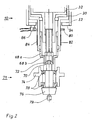
- the device 10 shown in FIG. 1 has a speed superposition gear 22 which consists of two planetary gears 24 and 26 arranged one behind the other with a common sun gear 28 and coaxial drives in the form of gear wheels 30 and 32.
- Each of the planetary gears 24 and 26 has three planet gears, of which only the planet gears 34 and 36 and 38 and 40 can be seen.
- Each of the planetary gears 24 and 26 also has a rotatably mounted planet carrier 24a or 26a.
- the sun gear 28 can be driven via a controllable sun gear rotation drive device (not shown) and the planet carrier 26a can be driven via a controllable planet carrier rotation drive device (not shown).
- the sun gear rotary drive device, the planet carrier rotary drive device and the speed superposition gear 22 are arranged on a movable carriage 42.
- the device 10 has a torque-switched coupling device for coupling the planet carrier 24a to a bearing ring 52.
- Said coupling device has a disk 50 made of hardened steel as a friction element, which is arranged between the planet carrier 24a and the bearing ring 52.
- the frictional torque is generated by pressing the disk 50 between the planet carrier 24a and the bearing ring 52.
- the required compressive force is transmitted from a rocker 54 to a pressure ring 56, which transmits the force to the disk 50 via a tensioning element 58, which acts as a spring when the force is low.
- the rocker 54 is set by means of a preload nut 60. The mounting of the rocker 54 is not shown.
- the coupling device also serves as a controllable fixing device for fixing the planet carrier 24a.
- it comprises a pneumatic cylinder 62.
- a clamping force is generated via the pneumatic cylinder 62 and increased by the transmission ratio of the rocker 54 to the required actuating force of the clamping element 58.
- Said tensioning element 58 non-positively connects the bearing ring 52 to the planet carrier 24a.
- the coupling device thus consists of the disk 50, the pressure ring 56, the tensioning element 58 and the rocker 54, the tensioning element 58 simultaneously belonging to the fixing device.
- the device also includes a detection device for detecting a rotational movement of the planet carrier 24a.
- the detection device comprises a toothed disk 64 on the planet carrier 24a and a sensor 66 for detecting the rotary movement.
- the planet carrier rotary drive device is switched on at a first speed in the same or opposite direction of rotation with respect to the sun wheel rotary drive device.
- the planet carrier 26a then rotates, while the planet carrier 24a remains braked.
- the land wheels 30 and 32 no longer run synchronously and thus a screwing movement, ie a screwing torque for screwing the components together.
- the step 30 blocks. There is no longer any screwing movement.
- step 30 is again forced to synchronize by the step 32, whereby a reaction via the planet gears 34 and 36 to the planet carrier 24a takes place in such a way that the planet carrier 24a is switched by the device for forming a torque Clutch formed slip slips.
- the planet carrier 24a rotates. The latter is in turn detected by sensor 66.
- the sensor 66 delivers a corresponding signal to the control device, which then lowers the speed of the planet carrier rotary drive device to a lower second speed for the final tightening of the screw connection element and essentially simultaneously activates the fixing device, that is to say the tensioning element 58 connects the bearing ring 52 and the planet carrier 24a in a force-locking manner ,
- the clamping element 58 exerts very large radial forces on the inside and outside diameter when flattening.
- the tensioning element 58 acts as a plate spring and presses the disk 50 against the surface on the planet carrier 24a.
- the full tightening torque for the final can then be transferred.
- the final tightening is basically limited either by the tightening torque or by the friction torque of the bearing.
- the measuring devices required for this are evaluated by the control device.
- the fixing device is deactivated and the planet carrier rotary drive device is switched off essentially at the same time.
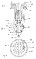
- FIG. 2 shows the lower part of a device 10 for the dynamic screwing of components according to a special embodiment of the invention, which is provided with a component 71 and which is provided with a screwing torque measuring device for measuring the screwing torque directly on a component 71 to be screwed.
- the component 71 is a bearing unit and comprises a drive flange 72, a component outer part 74, a shaft 76 and a bearing 78 in the form of two tapered roller bearings.
- a tip 79 is provided as a counter bearing for the component 71.
- the component 71 to be screwed is transported into the device 10 by means of a tool carrier (not shown) and positioned under a screwing tool inner part 68b.
- the screw torque measuring device comprises at least four strain gauges, of which only two are visible here and are identified by the reference numerals 82 and 84, for measuring the deformation (torsion) of the step 30, and a slip ring 80 rotating coaxially to the step 30 for detecting screw torque measuring signals from the strain gauges and a read head 86 for forwarding and amplifying tightening torque signals.
- the respective tightening torque can be measured directly on component 71.
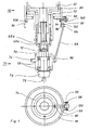
- Fig. 3 shows the lower, i.e. H. Part of a device 10 for the dynamic screwing of components facing a component 71 according to a further particular embodiment of the invention with a bearing friction torque measuring device which is fastened to the slide 42 shown in FIG. 1 via the bearing ring 52.
- the component 71 is constructed exactly as in FIG. 2. Due to the rotary movement, a bearing friction torque is generated by the bearing 78 in the form of two tapered roller bearings, which would cause the component outer part 74 to rotate.
- a support 88 is attached to a flange bore of the component outer part 74 (not marked) by means of a pin 90.
- the support 88 extends obliquely upward from the component outer part 74 to a bearing arm 94 for the bearing ring 52 and is fastened to it in any manner.
- a load cell 92 is integrated in the support 88. The load cell 92 is used to measure the applied support force.
- the bearing friction torque M R results from the product of the tangential force E at the point of articulation of the support 88 on the bearing arm 94 and the radius r, ie the distance between the axis of rotation of the component 71 and the pin 90.
- the arrangement of the support 88 (support) is different Component dependent and can e.g. B. in the form of a pull or push rod. In any case, the support 88 is connected to the component 71 and the bearing ring 52.
- the bearing friction torque measuring device comprises a support 88, which has one end is fastened by means of a pin 90 to the outer part 74 of the component and is connected with its other end, extending obliquely upwards, by means of two screws 102 and 104 to a ring 96 which extends coaxially to the step 30 and which in turn is connected to a load cell 92 via a holding arm 100 is connected, which in turn is connected to the bearing ring 52 via a holding arm 98.
- the ring 96 is also arranged on the bearing ring 52 by means of a bearing 106.
- the support torque is in turn measured via the load cell 92.
- the support can be adapted to different components more easily than in the embodiment shown in FIG. 3.
Landscapes
- Engineering & Computer Science (AREA)
- Mechanical Engineering (AREA)
- Retarders (AREA)
- Support Of The Bearing (AREA)
- Sliding-Contact Bearings (AREA)
- Force Measurement Appropriate To Specific Purposes (AREA)
- Transmission Devices (AREA)
- Details Of Spanners, Wrenches, And Screw Drivers And Accessories (AREA)
Applications Claiming Priority (2)
| Application Number | Priority Date | Filing Date | Title |
|---|---|---|---|
| DE10328983A DE10328983B4 (de) | 2003-06-27 | 2003-06-27 | Vorrichtung zum dynamischen Verschrauben von Bauteilen, insbesondere von Lager- und Getriebeeinheiten |
| DE10328983 | 2003-06-27 |
Publications (3)
| Publication Number | Publication Date |
|---|---|
| EP1491285A2 true EP1491285A2 (fr) | 2004-12-29 |
| EP1491285A3 EP1491285A3 (fr) | 2007-11-21 |
| EP1491285B1 EP1491285B1 (fr) | 2008-11-05 |
Family
ID=33395014
Family Applications (1)
| Application Number | Title | Priority Date | Filing Date |
|---|---|---|---|
| EP04014931A Expired - Lifetime EP1491285B1 (fr) | 2003-06-27 | 2004-06-25 | Dispositif et procédé de vissage dynamique des éléments, notamment des unités de paliers et transmission |
Country Status (3)
| Country | Link |
|---|---|
| EP (1) | EP1491285B1 (fr) |
| AT (1) | ATE413254T1 (fr) |
| DE (2) | DE10328983B4 (fr) |
Families Citing this family (1)
| Publication number | Priority date | Publication date | Assignee | Title |
|---|---|---|---|---|
| CN111945625B (zh) * | 2020-08-20 | 2022-02-25 | 陈荣才 | 一种市政设施拆除辅助装置 |
Family Cites Families (3)
| Publication number | Priority date | Publication date | Assignee | Title |
|---|---|---|---|---|
| US3596718A (en) * | 1969-07-02 | 1971-08-03 | Gardner Denver Co | Torque control system |
| DE4307131C2 (de) * | 1993-03-06 | 1995-11-16 | Albert Kipfelsberger | Kraftschrauber mit elektronischer Drehmomentbegrenzung |
| DE20110798U1 (de) * | 2001-06-29 | 2002-01-31 | Klimas, Joachim, 86316 Friedberg | Vorrichtung zum dynamischen Verschrauben von Bauteilen, insbesondere Lager- und Getriebeeinheiten |
-
2003
- 2003-06-27 DE DE10328983A patent/DE10328983B4/de not_active Expired - Fee Related
-
2004
- 2004-06-25 AT AT04014931T patent/ATE413254T1/de active
- 2004-06-25 EP EP04014931A patent/EP1491285B1/fr not_active Expired - Lifetime
- 2004-06-25 DE DE502004008381T patent/DE502004008381D1/de not_active Expired - Lifetime
Also Published As
| Publication number | Publication date |
|---|---|
| ATE413254T1 (de) | 2008-11-15 |
| DE502004008381D1 (de) | 2008-12-18 |
| DE10328983A1 (de) | 2005-01-27 |
| EP1491285B1 (fr) | 2008-11-05 |
| EP1491285A3 (fr) | 2007-11-21 |
| DE10328983B4 (de) | 2005-11-24 |
Similar Documents
| Publication | Publication Date | Title |
|---|---|---|
| DE69814439T2 (de) | Modulare betätigungsvorrichtung sowie bremssattel mit einer solchen betätigungsvorrichtung | |
| EP1579124B1 (fr) | Frein de stationnement commande lectrom canique | |
| DE10392252B4 (de) | Scheibenbremse | |
| EP0784162B1 (fr) | Détecteur d'usure de garniture de frein | |
| DE19629168C1 (de) | Windturbine mit einem Turm, einer Gondel und einer Bremse zum Arretieren der Schwenkbewegung der Gondel | |
| DE19611911A1 (de) | Bremsvorrichtung | |
| DE3629453C2 (fr) | ||
| EP1194709A1 (fr) | Engrenage planetaire a friction a roues coniques | |
| EP0239830B1 (fr) | Dispositif de réglage de la position angulaire relative entre une roue dentée et une couronne dentée coaxiale | |
| DE19510717C2 (de) | Elektrische Lenkvorrichtung für Flurförderzeuge | |
| DE9313282U1 (de) | Axialgewinderollkopf | |
| DE19605988A1 (de) | Vorrichtung zum Betätigen einer Radbremse eines Fahrzeuges | |
| EP1754566A1 (fr) | Table à transfert circulaire munie d'un dispositif de commande | |
| DE102009032808B4 (de) | Vorrichtung zum Messen einer Umwucht eines Fahrzeugrades | |
| EP0077890B1 (fr) | Palan électrique à chaîne | |
| EP3847123B1 (fr) | Grue et procédé de mise en girouette d'une telle grue | |
| EP1491285B1 (fr) | Dispositif et procédé de vissage dynamique des éléments, notamment des unités de paliers et transmission | |
| DE3624064C2 (fr) | ||
| EP0094377B1 (fr) | Dispositif pour régler rapidement la position réciproque de deux pièces, notamment pour des meubles de bureau | |
| EP0771648A1 (fr) | Dispositif de rattrapage de jeu dans une machine d'impression | |
| WO2022017553A1 (fr) | Procédé de réglage de force de précontrainte axiale d'entraînement à vis à rouleaux d'actionneur de dispositif de direction de véhicule à moteur | |
| DE3606039C2 (fr) | ||
| EP1931957B1 (fr) | Procede et dispositif pour controler l'effet de freinage d'un vehicule a moteur equipe d'au moins deux essieux entraines | |
| DE102018113697A1 (de) | Vorrichtung und Verfahren zur einstellbaren, synchronen Kraftübertragung auf mindestens zwei Zugmittel | |
| DE102006029943A1 (de) | Selbstverstärkende Scheibenbremse und Verfahren zu deren Ansteuerung |
Legal Events
| Date | Code | Title | Description |
|---|---|---|---|
| PUAI | Public reference made under article 153(3) epc to a published international application that has entered the european phase |
Free format text: ORIGINAL CODE: 0009012 |
|
| AK | Designated contracting states |
Kind code of ref document: A2 Designated state(s): AT BE BG CH CY CZ DE DK EE ES FI FR GB GR HU IE IT LI LU MC NL PL PT RO SE SI SK TR |
|
| AX | Request for extension of the european patent |
Extension state: AL HR LT LV MK |
|
| PUAL | Search report despatched |
Free format text: ORIGINAL CODE: 0009013 |
|
| AK | Designated contracting states |
Kind code of ref document: A3 Designated state(s): AT BE BG CH CY CZ DE DK EE ES FI FR GB GR HU IE IT LI LU MC NL PL PT RO SE SI SK TR |
|
| AX | Request for extension of the european patent |
Extension state: AL HR LT LV MK |
|
| 17P | Request for examination filed |
Effective date: 20080424 |
|
| GRAP | Despatch of communication of intention to grant a patent |
Free format text: ORIGINAL CODE: EPIDOSNIGR1 |
|
| AKX | Designation fees paid |
Designated state(s): AT BE BG CH CY CZ DE DK EE ES FI FR GB GR HU IE IT LI LU MC NL PL PT RO SE SI SK TR |
|
| GRAS | Grant fee paid |
Free format text: ORIGINAL CODE: EPIDOSNIGR3 |
|
| GRAA | (expected) grant |
Free format text: ORIGINAL CODE: 0009210 |
|
| AK | Designated contracting states |
Kind code of ref document: B1 Designated state(s): AT BE BG CH CY CZ DE DK EE ES FI FR GB GR HU IE IT LI LU MC NL PL PT RO SE SI SK TR |
|
| REG | Reference to a national code |
Ref country code: GB Ref legal event code: FG4D Free format text: NOT ENGLISH |
|
| REG | Reference to a national code |
Ref country code: CH Ref legal event code: EP |
|
| REG | Reference to a national code |
Ref country code: IE Ref legal event code: FG4D Free format text: LANGUAGE OF EP DOCUMENT: GERMAN |
|
| REF | Corresponds to: |
Ref document number: 502004008381 Country of ref document: DE Date of ref document: 20081218 Kind code of ref document: P |
|
| NLV1 | Nl: lapsed or annulled due to failure to fulfill the requirements of art. 29p and 29m of the patents act | ||
| PG25 | Lapsed in a contracting state [announced via postgrant information from national office to epo] |
Ref country code: ES Free format text: LAPSE BECAUSE OF FAILURE TO SUBMIT A TRANSLATION OF THE DESCRIPTION OR TO PAY THE FEE WITHIN THE PRESCRIBED TIME-LIMIT Effective date: 20090216 |
|
| PG25 | Lapsed in a contracting state [announced via postgrant information from national office to epo] |
Ref country code: PL Free format text: LAPSE BECAUSE OF FAILURE TO SUBMIT A TRANSLATION OF THE DESCRIPTION OR TO PAY THE FEE WITHIN THE PRESCRIBED TIME-LIMIT Effective date: 20081105 Ref country code: SI Free format text: LAPSE BECAUSE OF FAILURE TO SUBMIT A TRANSLATION OF THE DESCRIPTION OR TO PAY THE FEE WITHIN THE PRESCRIBED TIME-LIMIT Effective date: 20081105 Ref country code: FI Free format text: LAPSE BECAUSE OF FAILURE TO SUBMIT A TRANSLATION OF THE DESCRIPTION OR TO PAY THE FEE WITHIN THE PRESCRIBED TIME-LIMIT Effective date: 20081105 Ref country code: NL Free format text: LAPSE BECAUSE OF FAILURE TO SUBMIT A TRANSLATION OF THE DESCRIPTION OR TO PAY THE FEE WITHIN THE PRESCRIBED TIME-LIMIT Effective date: 20081105 |
|
| REG | Reference to a national code |
Ref country code: IE Ref legal event code: FD4D |
|
| PG25 | Lapsed in a contracting state [announced via postgrant information from national office to epo] |
Ref country code: RO Free format text: LAPSE BECAUSE OF FAILURE TO SUBMIT A TRANSLATION OF THE DESCRIPTION OR TO PAY THE FEE WITHIN THE PRESCRIBED TIME-LIMIT Effective date: 20081105 Ref country code: DK Free format text: LAPSE BECAUSE OF FAILURE TO SUBMIT A TRANSLATION OF THE DESCRIPTION OR TO PAY THE FEE WITHIN THE PRESCRIBED TIME-LIMIT Effective date: 20081105 Ref country code: IE Free format text: LAPSE BECAUSE OF FAILURE TO SUBMIT A TRANSLATION OF THE DESCRIPTION OR TO PAY THE FEE WITHIN THE PRESCRIBED TIME-LIMIT Effective date: 20081105 Ref country code: BG Free format text: LAPSE BECAUSE OF FAILURE TO SUBMIT A TRANSLATION OF THE DESCRIPTION OR TO PAY THE FEE WITHIN THE PRESCRIBED TIME-LIMIT Effective date: 20090205 Ref country code: EE Free format text: LAPSE BECAUSE OF FAILURE TO SUBMIT A TRANSLATION OF THE DESCRIPTION OR TO PAY THE FEE WITHIN THE PRESCRIBED TIME-LIMIT Effective date: 20081105 |
|
| PG25 | Lapsed in a contracting state [announced via postgrant information from national office to epo] |
Ref country code: CZ Free format text: LAPSE BECAUSE OF FAILURE TO SUBMIT A TRANSLATION OF THE DESCRIPTION OR TO PAY THE FEE WITHIN THE PRESCRIBED TIME-LIMIT Effective date: 20081105 Ref country code: PT Free format text: LAPSE BECAUSE OF FAILURE TO SUBMIT A TRANSLATION OF THE DESCRIPTION OR TO PAY THE FEE WITHIN THE PRESCRIBED TIME-LIMIT Effective date: 20090406 Ref country code: SE Free format text: LAPSE BECAUSE OF FAILURE TO SUBMIT A TRANSLATION OF THE DESCRIPTION OR TO PAY THE FEE WITHIN THE PRESCRIBED TIME-LIMIT Effective date: 20090205 |
|
| PLBE | No opposition filed within time limit |
Free format text: ORIGINAL CODE: 0009261 |
|
| STAA | Information on the status of an ep patent application or granted ep patent |
Free format text: STATUS: NO OPPOSITION FILED WITHIN TIME LIMIT |
|
| PG25 | Lapsed in a contracting state [announced via postgrant information from national office to epo] |
Ref country code: SK Free format text: LAPSE BECAUSE OF FAILURE TO SUBMIT A TRANSLATION OF THE DESCRIPTION OR TO PAY THE FEE WITHIN THE PRESCRIBED TIME-LIMIT Effective date: 20081105 |
|
| 26N | No opposition filed |
Effective date: 20090806 |
|
| BERE | Be: lapsed |
Owner name: KLIMAS, JOACHIM Effective date: 20090630 |
|
| PG25 | Lapsed in a contracting state [announced via postgrant information from national office to epo] |
Ref country code: MC Free format text: LAPSE BECAUSE OF NON-PAYMENT OF DUE FEES Effective date: 20090630 |
|
| REG | Reference to a national code |
Ref country code: CH Ref legal event code: PL |
|
| GBPC | Gb: european patent ceased through non-payment of renewal fee |
Effective date: 20090625 |
|
| REG | Reference to a national code |
Ref country code: FR Ref legal event code: ST Effective date: 20100226 |
|
| PG25 | Lapsed in a contracting state [announced via postgrant information from national office to epo] |
Ref country code: CH Free format text: LAPSE BECAUSE OF NON-PAYMENT OF DUE FEES Effective date: 20090630 Ref country code: LI Free format text: LAPSE BECAUSE OF NON-PAYMENT OF DUE FEES Effective date: 20090630 Ref country code: FR Free format text: LAPSE BECAUSE OF NON-PAYMENT OF DUE FEES Effective date: 20090630 |
|
| PG25 | Lapsed in a contracting state [announced via postgrant information from national office to epo] |
Ref country code: GB Free format text: LAPSE BECAUSE OF NON-PAYMENT OF DUE FEES Effective date: 20090625 |
|
| PG25 | Lapsed in a contracting state [announced via postgrant information from national office to epo] |
Ref country code: BE Free format text: LAPSE BECAUSE OF NON-PAYMENT OF DUE FEES Effective date: 20090630 |
|
| PG25 | Lapsed in a contracting state [announced via postgrant information from national office to epo] |
Ref country code: GR Free format text: LAPSE BECAUSE OF FAILURE TO SUBMIT A TRANSLATION OF THE DESCRIPTION OR TO PAY THE FEE WITHIN THE PRESCRIBED TIME-LIMIT Effective date: 20090206 |
|
| PG25 | Lapsed in a contracting state [announced via postgrant information from national office to epo] |
Ref country code: LU Free format text: LAPSE BECAUSE OF NON-PAYMENT OF DUE FEES Effective date: 20090625 |
|
| PG25 | Lapsed in a contracting state [announced via postgrant information from national office to epo] |
Ref country code: HU Free format text: LAPSE BECAUSE OF FAILURE TO SUBMIT A TRANSLATION OF THE DESCRIPTION OR TO PAY THE FEE WITHIN THE PRESCRIBED TIME-LIMIT Effective date: 20090506 |
|
| PG25 | Lapsed in a contracting state [announced via postgrant information from national office to epo] |
Ref country code: TR Free format text: LAPSE BECAUSE OF FAILURE TO SUBMIT A TRANSLATION OF THE DESCRIPTION OR TO PAY THE FEE WITHIN THE PRESCRIBED TIME-LIMIT Effective date: 20081105 |
|
| PG25 | Lapsed in a contracting state [announced via postgrant information from national office to epo] |
Ref country code: CY Free format text: LAPSE BECAUSE OF FAILURE TO SUBMIT A TRANSLATION OF THE DESCRIPTION OR TO PAY THE FEE WITHIN THE PRESCRIBED TIME-LIMIT Effective date: 20081105 |
|
| PGFP | Annual fee paid to national office [announced via postgrant information from national office to epo] |
Ref country code: AT Payment date: 20120529 Year of fee payment: 9 |
|
| PGFP | Annual fee paid to national office [announced via postgrant information from national office to epo] |
Ref country code: DE Payment date: 20130627 Year of fee payment: 10 |
|
| PGFP | Annual fee paid to national office [announced via postgrant information from national office to epo] |
Ref country code: IT Payment date: 20130620 Year of fee payment: 10 |
|
| REG | Reference to a national code |
Ref country code: DE Ref legal event code: R119 Ref document number: 502004008381 Country of ref document: DE |
|
| REG | Reference to a national code |
Ref country code: AT Ref legal event code: MM01 Ref document number: 413254 Country of ref document: AT Kind code of ref document: T Effective date: 20140625 |
|
| REG | Reference to a national code |
Ref country code: DE Ref legal event code: R119 Ref document number: 502004008381 Country of ref document: DE Effective date: 20150101 |
|
| PG25 | Lapsed in a contracting state [announced via postgrant information from national office to epo] |
Ref country code: IT Free format text: LAPSE BECAUSE OF NON-PAYMENT OF DUE FEES Effective date: 20140625 Ref country code: DE Free format text: LAPSE BECAUSE OF NON-PAYMENT OF DUE FEES Effective date: 20150101 |
|
| PG25 | Lapsed in a contracting state [announced via postgrant information from national office to epo] |
Ref country code: AT Free format text: LAPSE BECAUSE OF NON-PAYMENT OF DUE FEES Effective date: 20140625 |