EP1491310B1 - Procede et appareil de liberation d'un joint metal-resine - Google Patents
Procede et appareil de liberation d'un joint metal-resine Download PDFInfo
- Publication number
- EP1491310B1 EP1491310B1 EP20030725672 EP03725672A EP1491310B1 EP 1491310 B1 EP1491310 B1 EP 1491310B1 EP 20030725672 EP20030725672 EP 20030725672 EP 03725672 A EP03725672 A EP 03725672A EP 1491310 B1 EP1491310 B1 EP 1491310B1
- Authority
- EP
- European Patent Office
- Prior art keywords
- metal
- resin
- joint
- separating
- alkaline solution
- Prior art date
- Legal status (The legal status is an assumption and is not a legal conclusion. Google has not performed a legal analysis and makes no representation as to the accuracy of the status listed.)
- Expired - Lifetime
Links
- 229920005989 resin Polymers 0.000 title claims abstract description 166
- 239000011347 resin Substances 0.000 title claims abstract description 166
- 238000000034 method Methods 0.000 title claims abstract description 41
- 229910052751 metal Inorganic materials 0.000 claims abstract description 136
- 239000002184 metal Substances 0.000 claims abstract description 136
- UFHFLCQGNIYNRP-UHFFFAOYSA-N Hydrogen Chemical compound [H][H] UFHFLCQGNIYNRP-UHFFFAOYSA-N 0.000 claims abstract description 39
- 239000001257 hydrogen Substances 0.000 claims abstract description 36
- 229910052739 hydrogen Inorganic materials 0.000 claims abstract description 36
- 239000002699 waste material Substances 0.000 claims abstract description 11
- 238000004064 recycling Methods 0.000 claims abstract description 10
- 239000012670 alkaline solution Substances 0.000 claims description 61
- 239000000463 material Substances 0.000 claims description 34
- 239000000853 adhesive Substances 0.000 claims description 18
- 230000001070 adhesive effect Effects 0.000 claims description 18
- -1 alkali metal cations Chemical class 0.000 claims description 11
- 229910052802 copper Inorganic materials 0.000 claims description 10
- XLYOFNOQVPJJNP-UHFFFAOYSA-M hydroxide Chemical compound [OH-] XLYOFNOQVPJJNP-UHFFFAOYSA-M 0.000 claims description 10
- 229910052759 nickel Inorganic materials 0.000 claims description 10
- 239000003822 epoxy resin Substances 0.000 claims description 9
- 229910052742 iron Inorganic materials 0.000 claims description 9
- 229910052753 mercury Inorganic materials 0.000 claims description 9
- 229920000647 polyepoxide Polymers 0.000 claims description 9
- 229910052782 aluminium Inorganic materials 0.000 claims description 8
- 239000004020 conductor Substances 0.000 claims description 8
- 229910052718 tin Inorganic materials 0.000 claims description 8
- 229910052725 zinc Inorganic materials 0.000 claims description 8
- 229920003051 synthetic elastomer Polymers 0.000 claims description 7
- 239000005061 synthetic rubber Substances 0.000 claims description 7
- 239000005011 phenolic resin Substances 0.000 claims description 6
- 239000002390 adhesive tape Substances 0.000 claims description 5
- 229910052804 chromium Inorganic materials 0.000 claims description 5
- 229910052737 gold Inorganic materials 0.000 claims description 5
- 229920000642 polymer Polymers 0.000 claims description 5
- 229910052709 silver Inorganic materials 0.000 claims description 5
- 229910052719 titanium Inorganic materials 0.000 claims description 5
- RTZKZFJDLAIYFH-UHFFFAOYSA-N Diethyl ether Chemical compound CCOCC RTZKZFJDLAIYFH-UHFFFAOYSA-N 0.000 claims description 4
- 229930182556 Polyacetal Natural products 0.000 claims description 4
- 229910052783 alkali metal Inorganic materials 0.000 claims description 4
- 238000001746 injection moulding Methods 0.000 claims description 4
- 229910052741 iridium Inorganic materials 0.000 claims description 4
- 229910052750 molybdenum Inorganic materials 0.000 claims description 4
- 229910052762 osmium Inorganic materials 0.000 claims description 4
- 229910052763 palladium Inorganic materials 0.000 claims description 4
- 229910052697 platinum Inorganic materials 0.000 claims description 4
- 229920000412 polyarylene Polymers 0.000 claims description 4
- 229920000515 polycarbonate Polymers 0.000 claims description 4
- 239000004417 polycarbonate Substances 0.000 claims description 4
- 229920000098 polyolefin Polymers 0.000 claims description 4
- 229920006324 polyoxymethylene Polymers 0.000 claims description 4
- 229920000915 polyvinyl chloride Polymers 0.000 claims description 4
- 239000004800 polyvinyl chloride Substances 0.000 claims description 4
- 229910052702 rhenium Inorganic materials 0.000 claims description 4
- 229910052703 rhodium Inorganic materials 0.000 claims description 4
- 229920000178 Acrylic resin Polymers 0.000 claims description 3
- 239000004925 Acrylic resin Substances 0.000 claims description 3
- 229920000459 Nitrile rubber Polymers 0.000 claims description 3
- 229910052748 manganese Inorganic materials 0.000 claims description 3
- 229920001651 Cyanoacrylate Polymers 0.000 claims description 2
- 244000043261 Hevea brasiliensis Species 0.000 claims description 2
- MWCLLHOVUTZFKS-UHFFFAOYSA-N Methyl cyanoacrylate Chemical compound COC(=O)C(=C)C#N MWCLLHOVUTZFKS-UHFFFAOYSA-N 0.000 claims description 2
- 239000004952 Polyamide Substances 0.000 claims description 2
- 239000004642 Polyimide Substances 0.000 claims description 2
- UCKMPCXJQFINFW-UHFFFAOYSA-N Sulphide Chemical compound [S-2] UCKMPCXJQFINFW-UHFFFAOYSA-N 0.000 claims description 2
- XTXRWKRVRITETP-UHFFFAOYSA-N Vinyl acetate Chemical compound CC(=O)OC=C XTXRWKRVRITETP-UHFFFAOYSA-N 0.000 claims description 2
- 229910052745 lead Inorganic materials 0.000 claims description 2
- 229920003052 natural elastomer Polymers 0.000 claims description 2
- 229920001194 natural rubber Polymers 0.000 claims description 2
- 229920001643 poly(ether ketone) Polymers 0.000 claims description 2
- 229920002492 poly(sulfone) Polymers 0.000 claims description 2
- 229920002647 polyamide Polymers 0.000 claims description 2
- 229920000728 polyester Polymers 0.000 claims description 2
- 229920001721 polyimide Polymers 0.000 claims description 2
- 229920002635 polyurethane Polymers 0.000 claims description 2
- 239000004814 polyurethane Substances 0.000 claims description 2
- 229920002050 silicone resin Polymers 0.000 claims description 2
- 238000004073 vulcanization Methods 0.000 claims description 2
- 239000003513 alkali Substances 0.000 abstract description 7
- 239000002585 base Substances 0.000 abstract 1
- 238000000926 separation method Methods 0.000 description 46
- HEMHJVSKTPXQMS-UHFFFAOYSA-M Sodium hydroxide Chemical compound [OH-].[Na+] HEMHJVSKTPXQMS-UHFFFAOYSA-M 0.000 description 36
- 229910000831 Steel Inorganic materials 0.000 description 24
- 239000010959 steel Substances 0.000 description 24
- PXHVJJICTQNCMI-UHFFFAOYSA-N nickel Substances [Ni] PXHVJJICTQNCMI-UHFFFAOYSA-N 0.000 description 15
- XEEYBQQBJWHFJM-UHFFFAOYSA-N Iron Chemical compound [Fe] XEEYBQQBJWHFJM-UHFFFAOYSA-N 0.000 description 14
- 239000002131 composite material Substances 0.000 description 13
- 239000011133 lead Substances 0.000 description 12
- 239000007864 aqueous solution Substances 0.000 description 11
- 238000012360 testing method Methods 0.000 description 11
- RYGMFSIKBFXOCR-UHFFFAOYSA-N Copper Chemical compound [Cu] RYGMFSIKBFXOCR-UHFFFAOYSA-N 0.000 description 9
- NIXOWILDQLNWCW-UHFFFAOYSA-N acrylic acid group Chemical group C(C=C)(=O)O NIXOWILDQLNWCW-UHFFFAOYSA-N 0.000 description 9
- 239000010949 copper Substances 0.000 description 9
- 238000001612 separation test Methods 0.000 description 9
- XLYOFNOQVPJJNP-UHFFFAOYSA-N water Substances O XLYOFNOQVPJJNP-UHFFFAOYSA-N 0.000 description 9
- 238000000576 coating method Methods 0.000 description 8
- 239000011248 coating agent Substances 0.000 description 7
- 239000011135 tin Substances 0.000 description 7
- 239000011701 zinc Substances 0.000 description 7
- QVGXLLKOCUKJST-UHFFFAOYSA-N atomic oxygen Chemical compound [O] QVGXLLKOCUKJST-UHFFFAOYSA-N 0.000 description 6
- 239000000470 constituent Substances 0.000 description 6
- QSHDDOUJBYECFT-UHFFFAOYSA-N mercury Chemical compound [Hg] QSHDDOUJBYECFT-UHFFFAOYSA-N 0.000 description 6
- 239000007769 metal material Substances 0.000 description 6
- 239000001301 oxygen Substances 0.000 description 6
- 229910052760 oxygen Inorganic materials 0.000 description 6
- 239000002966 varnish Substances 0.000 description 6
- ATJFFYVFTNAWJD-UHFFFAOYSA-N Tin Chemical compound [Sn] ATJFFYVFTNAWJD-UHFFFAOYSA-N 0.000 description 5
- HCHKCACWOHOZIP-UHFFFAOYSA-N Zinc Chemical compound [Zn] HCHKCACWOHOZIP-UHFFFAOYSA-N 0.000 description 5
- XAGFODPZIPBFFR-UHFFFAOYSA-N aluminium Chemical compound [Al] XAGFODPZIPBFFR-UHFFFAOYSA-N 0.000 description 5
- 239000008151 electrolyte solution Substances 0.000 description 5
- 239000011521 glass Substances 0.000 description 5
- 229910000474 mercury oxide Inorganic materials 0.000 description 5
- UKWHYYKOEPRTIC-UHFFFAOYSA-N mercury(ii) oxide Chemical compound [Hg]=O UKWHYYKOEPRTIC-UHFFFAOYSA-N 0.000 description 5
- KDLHZDBZIXYQEI-UHFFFAOYSA-N palladium Substances [Pd] KDLHZDBZIXYQEI-UHFFFAOYSA-N 0.000 description 5
- BASFCYQUMIYNBI-UHFFFAOYSA-N platinum Substances [Pt] BASFCYQUMIYNBI-UHFFFAOYSA-N 0.000 description 5
- 239000000758 substrate Substances 0.000 description 5
- IJGRMHOSHXDMSA-UHFFFAOYSA-N Atomic nitrogen Chemical compound N#N IJGRMHOSHXDMSA-UHFFFAOYSA-N 0.000 description 4
- 239000011651 chromium Substances 0.000 description 4
- 239000003792 electrolyte Substances 0.000 description 4
- 239000010931 gold Substances 0.000 description 4
- 238000010297 mechanical methods and process Methods 0.000 description 4
- 239000002904 solvent Substances 0.000 description 4
- 239000010936 titanium Substances 0.000 description 4
- 229910001369 Brass Inorganic materials 0.000 description 3
- OKKJLVBELUTLKV-UHFFFAOYSA-N Methanol Chemical compound OC OKKJLVBELUTLKV-UHFFFAOYSA-N 0.000 description 3
- KWYUFKZDYYNOTN-UHFFFAOYSA-M Potassium hydroxide Chemical compound [OH-].[K+] KWYUFKZDYYNOTN-UHFFFAOYSA-M 0.000 description 3
- 239000010951 brass Substances 0.000 description 3
- 230000007797 corrosion Effects 0.000 description 3
- 238000005260 corrosion Methods 0.000 description 3
- 230000006378 damage Effects 0.000 description 3
- 238000004090 dissolution Methods 0.000 description 3
- 238000005868 electrolysis reaction Methods 0.000 description 3
- 230000005484 gravity Effects 0.000 description 3
- 239000007788 liquid Substances 0.000 description 3
- 150000002739 metals Chemical class 0.000 description 3
- 239000003973 paint Substances 0.000 description 3
- 238000007747 plating Methods 0.000 description 3
- 238000006722 reduction reaction Methods 0.000 description 3
- 239000010948 rhodium Substances 0.000 description 3
- BFKJFAAPBSQJPD-UHFFFAOYSA-N tetrafluoroethene Chemical group FC(F)=C(F)F BFKJFAAPBSQJPD-UHFFFAOYSA-N 0.000 description 3
- 229910000497 Amalgam Inorganic materials 0.000 description 2
- CURLTUGMZLYLDI-UHFFFAOYSA-N Carbon dioxide Chemical compound O=C=O CURLTUGMZLYLDI-UHFFFAOYSA-N 0.000 description 2
- VYZAMTAEIAYCRO-UHFFFAOYSA-N Chromium Chemical compound [Cr] VYZAMTAEIAYCRO-UHFFFAOYSA-N 0.000 description 2
- ZOKXTWBITQBERF-UHFFFAOYSA-N Molybdenum Chemical compound [Mo] ZOKXTWBITQBERF-UHFFFAOYSA-N 0.000 description 2
- 239000004721 Polyphenylene oxide Substances 0.000 description 2
- 239000004734 Polyphenylene sulfide Substances 0.000 description 2
- VYPSYNLAJGMNEJ-UHFFFAOYSA-N Silicium dioxide Chemical compound O=[Si]=O VYPSYNLAJGMNEJ-UHFFFAOYSA-N 0.000 description 2
- BQCADISMDOOEFD-UHFFFAOYSA-N Silver Chemical compound [Ag] BQCADISMDOOEFD-UHFFFAOYSA-N 0.000 description 2
- CDBYLPFSWZWCQE-UHFFFAOYSA-L Sodium Carbonate Chemical compound [Na+].[Na+].[O-]C([O-])=O CDBYLPFSWZWCQE-UHFFFAOYSA-L 0.000 description 2
- PPBRXRYQALVLMV-UHFFFAOYSA-N Styrene Chemical compound C=CC1=CC=CC=C1 PPBRXRYQALVLMV-UHFFFAOYSA-N 0.000 description 2
- RTAQQCXQSZGOHL-UHFFFAOYSA-N Titanium Chemical compound [Ti] RTAQQCXQSZGOHL-UHFFFAOYSA-N 0.000 description 2
- 230000015572 biosynthetic process Effects 0.000 description 2
- 238000004140 cleaning Methods 0.000 description 2
- 229910017052 cobalt Inorganic materials 0.000 description 2
- 239000010941 cobalt Substances 0.000 description 2
- GUTLYIVDDKVIGB-UHFFFAOYSA-N cobalt atom Chemical compound [Co] GUTLYIVDDKVIGB-UHFFFAOYSA-N 0.000 description 2
- 239000011889 copper foil Substances 0.000 description 2
- 238000011161 development Methods 0.000 description 2
- 230000000694 effects Effects 0.000 description 2
- 238000002848 electrochemical method Methods 0.000 description 2
- 238000005516 engineering process Methods 0.000 description 2
- PCHJSUWPFVWCPO-UHFFFAOYSA-N gold Chemical compound [Au] PCHJSUWPFVWCPO-UHFFFAOYSA-N 0.000 description 2
- GKOZUEZYRPOHIO-UHFFFAOYSA-N iridium atom Chemical compound [Ir] GKOZUEZYRPOHIO-UHFFFAOYSA-N 0.000 description 2
- 229910052749 magnesium Inorganic materials 0.000 description 2
- 239000011777 magnesium Substances 0.000 description 2
- 239000011572 manganese Substances 0.000 description 2
- 238000004519 manufacturing process Methods 0.000 description 2
- 238000005259 measurement Methods 0.000 description 2
- 239000011733 molybdenum Substances 0.000 description 2
- 238000000465 moulding Methods 0.000 description 2
- 229910052757 nitrogen Inorganic materials 0.000 description 2
- 239000012811 non-conductive material Substances 0.000 description 2
- SYQBFIAQOQZEGI-UHFFFAOYSA-N osmium atom Chemical compound [Os] SYQBFIAQOQZEGI-UHFFFAOYSA-N 0.000 description 2
- 230000003647 oxidation Effects 0.000 description 2
- 238000007254 oxidation reaction Methods 0.000 description 2
- 229920000570 polyether Polymers 0.000 description 2
- 229920000069 polyphenylene sulfide Polymers 0.000 description 2
- BWHMMNNQKKPAPP-UHFFFAOYSA-L potassium carbonate Chemical compound [K+].[K+].[O-]C([O-])=O BWHMMNNQKKPAPP-UHFFFAOYSA-L 0.000 description 2
- WUAPFZMCVAUBPE-UHFFFAOYSA-N rhenium atom Chemical compound [Re] WUAPFZMCVAUBPE-UHFFFAOYSA-N 0.000 description 2
- MHOVAHRLVXNVSD-UHFFFAOYSA-N rhodium atom Chemical compound [Rh] MHOVAHRLVXNVSD-UHFFFAOYSA-N 0.000 description 2
- 239000004332 silver Substances 0.000 description 2
- 239000010944 silver (metal) Substances 0.000 description 2
- 239000010935 stainless steel Substances 0.000 description 2
- 229910001220 stainless steel Inorganic materials 0.000 description 2
- 238000003756 stirring Methods 0.000 description 2
- HGUFODBRKLSHSI-UHFFFAOYSA-N 2,3,7,8-tetrachloro-dibenzo-p-dioxin Chemical compound O1C2=CC(Cl)=C(Cl)C=C2OC2=C1C=C(Cl)C(Cl)=C2 HGUFODBRKLSHSI-UHFFFAOYSA-N 0.000 description 1
- AEQDJSLRWYMAQI-UHFFFAOYSA-N 2,3,9,10-tetramethoxy-6,8,13,13a-tetrahydro-5H-isoquinolino[2,1-b]isoquinoline Chemical compound C1CN2CC(C(=C(OC)C=C3)OC)=C3CC2C2=C1C=C(OC)C(OC)=C2 AEQDJSLRWYMAQI-UHFFFAOYSA-N 0.000 description 1
- 229920003319 Araldite® Polymers 0.000 description 1
- BVKZGUZCCUSVTD-UHFFFAOYSA-L Carbonate Chemical compound [O-]C([O-])=O BVKZGUZCCUSVTD-UHFFFAOYSA-L 0.000 description 1
- QPLDLSVMHZLSFG-UHFFFAOYSA-N Copper oxide Chemical compound [Cu]=O QPLDLSVMHZLSFG-UHFFFAOYSA-N 0.000 description 1
- 239000005751 Copper oxide Substances 0.000 description 1
- 235000002918 Fraxinus excelsior Nutrition 0.000 description 1
- FYYHWMGAXLPEAU-UHFFFAOYSA-N Magnesium Chemical compound [Mg] FYYHWMGAXLPEAU-UHFFFAOYSA-N 0.000 description 1
- PWHULOQIROXLJO-UHFFFAOYSA-N Manganese Chemical compound [Mn] PWHULOQIROXLJO-UHFFFAOYSA-N 0.000 description 1
- KKCBUQHMOMHUOY-UHFFFAOYSA-N Na2O Inorganic materials [O-2].[Na+].[Na+] KKCBUQHMOMHUOY-UHFFFAOYSA-N 0.000 description 1
- ISWSIDIOOBJBQZ-UHFFFAOYSA-N Phenol Chemical compound OC1=CC=CC=C1 ISWSIDIOOBJBQZ-UHFFFAOYSA-N 0.000 description 1
- 239000004698 Polyethylene Substances 0.000 description 1
- 239000004743 Polypropylene Substances 0.000 description 1
- 239000004793 Polystyrene Substances 0.000 description 1
- 229910045601 alloy Inorganic materials 0.000 description 1
- 239000000956 alloy Substances 0.000 description 1
- 239000002956 ash Substances 0.000 description 1
- 229910052788 barium Inorganic materials 0.000 description 1
- 229910052796 boron Inorganic materials 0.000 description 1
- 229910052791 calcium Inorganic materials 0.000 description 1
- WUKWITHWXAAZEY-UHFFFAOYSA-L calcium difluoride Chemical compound [F-].[F-].[Ca+2] WUKWITHWXAAZEY-UHFFFAOYSA-L 0.000 description 1
- 229910001634 calcium fluoride Inorganic materials 0.000 description 1
- 239000001569 carbon dioxide Substances 0.000 description 1
- 229910002092 carbon dioxide Inorganic materials 0.000 description 1
- 239000003518 caustics Substances 0.000 description 1
- 238000005119 centrifugation Methods 0.000 description 1
- 229910052681 coesite Inorganic materials 0.000 description 1
- 239000000805 composite resin Substances 0.000 description 1
- 238000007796 conventional method Methods 0.000 description 1
- 229910000431 copper oxide Inorganic materials 0.000 description 1
- MNEVGNCIZWZKLR-UHFFFAOYSA-N copper;phenol Chemical compound [Cu].OC1=CC=CC=C1.OC1=CC=CC=C1 MNEVGNCIZWZKLR-UHFFFAOYSA-N 0.000 description 1
- 229910052906 cristobalite Inorganic materials 0.000 description 1
- 238000000354 decomposition reaction Methods 0.000 description 1
- 230000003247 decreasing effect Effects 0.000 description 1
- 210000003298 dental enamel Anatomy 0.000 description 1
- 230000001419 dependent effect Effects 0.000 description 1
- 238000002845 discoloration Methods 0.000 description 1
- 238000009713 electroplating Methods 0.000 description 1
- 239000000839 emulsion Substances 0.000 description 1
- 238000005265 energy consumption Methods 0.000 description 1
- 230000007613 environmental effect Effects 0.000 description 1
- 238000010438 heat treatment Methods 0.000 description 1
- 238000002347 injection Methods 0.000 description 1
- 239000007924 injection Substances 0.000 description 1
- 230000009545 invasion Effects 0.000 description 1
- 239000011630 iodine Substances 0.000 description 1
- 229910052740 iodine Inorganic materials 0.000 description 1
- 239000002655 kraft paper Substances 0.000 description 1
- FPYJFEHAWHCUMM-UHFFFAOYSA-N maleic anhydride Chemical compound O=C1OC(=O)C=C1 FPYJFEHAWHCUMM-UHFFFAOYSA-N 0.000 description 1
- WPBNNNQJVZRUHP-UHFFFAOYSA-L manganese(2+);methyl n-[[2-(methoxycarbonylcarbamothioylamino)phenyl]carbamothioyl]carbamate;n-[2-(sulfidocarbothioylamino)ethyl]carbamodithioate Chemical compound [Mn+2].[S-]C(=S)NCCNC([S-])=S.COC(=O)NC(=S)NC1=CC=CC=C1NC(=S)NC(=O)OC WPBNNNQJVZRUHP-UHFFFAOYSA-L 0.000 description 1
- 239000003595 mist Substances 0.000 description 1
- 238000012544 monitoring process Methods 0.000 description 1
- 230000007935 neutral effect Effects 0.000 description 1
- 239000000123 paper Substances 0.000 description 1
- 239000011236 particulate material Substances 0.000 description 1
- 229920003229 poly(methyl methacrylate) Polymers 0.000 description 1
- 229920002721 polycyanoacrylate Polymers 0.000 description 1
- 229920001225 polyester resin Polymers 0.000 description 1
- 239000004645 polyester resin Substances 0.000 description 1
- 229920000573 polyethylene Polymers 0.000 description 1
- 239000004926 polymethyl methacrylate Substances 0.000 description 1
- 229920001155 polypropylene Polymers 0.000 description 1
- 229920002223 polystyrene Polymers 0.000 description 1
- 229920002689 polyvinyl acetate Polymers 0.000 description 1
- 239000011118 polyvinyl acetate Substances 0.000 description 1
- 229940075065 polyvinyl acetate Drugs 0.000 description 1
- 229910052700 potassium Inorganic materials 0.000 description 1
- 229910000027 potassium carbonate Inorganic materials 0.000 description 1
- 238000002360 preparation method Methods 0.000 description 1
- 230000001737 promoting effect Effects 0.000 description 1
- 238000010298 pulverizing process Methods 0.000 description 1
- 229910052710 silicon Inorganic materials 0.000 description 1
- 239000000377 silicon dioxide Substances 0.000 description 1
- 229910052708 sodium Inorganic materials 0.000 description 1
- 239000011734 sodium Substances 0.000 description 1
- 229910000029 sodium carbonate Inorganic materials 0.000 description 1
- 239000000176 sodium gluconate Substances 0.000 description 1
- 229940005574 sodium gluconate Drugs 0.000 description 1
- 235000012207 sodium gluconate Nutrition 0.000 description 1
- 229910000679 solder Inorganic materials 0.000 description 1
- 239000000243 solution Substances 0.000 description 1
- 229910052682 stishovite Inorganic materials 0.000 description 1
- 239000000126 substance Substances 0.000 description 1
- 229910052905 tridymite Inorganic materials 0.000 description 1
- 125000000391 vinyl group Chemical group [H]C([*])=C([H])[H] 0.000 description 1
- 229920002554 vinyl polymer Polymers 0.000 description 1
- 239000000037 vitreous enamel Substances 0.000 description 1
- 238000010792 warming Methods 0.000 description 1
- 238000005406 washing Methods 0.000 description 1
- 229910052727 yttrium Inorganic materials 0.000 description 1
- 229910052726 zirconium Inorganic materials 0.000 description 1
Images


Classifications
-
- B—PERFORMING OPERATIONS; TRANSPORTING
- B29—WORKING OF PLASTICS; WORKING OF SUBSTANCES IN A PLASTIC STATE IN GENERAL
- B29B—PREPARATION OR PRETREATMENT OF THE MATERIAL TO BE SHAPED; MAKING GRANULES OR PREFORMS; RECOVERY OF PLASTICS OR OTHER CONSTITUENTS OF WASTE MATERIAL CONTAINING PLASTICS
- B29B17/00—Recovery of plastics or other constituents of waste material containing plastics
- B29B17/04—Disintegrating plastics, e.g. by milling
-
- B—PERFORMING OPERATIONS; TRANSPORTING
- B29—WORKING OF PLASTICS; WORKING OF SUBSTANCES IN A PLASTIC STATE IN GENERAL
- B29B—PREPARATION OR PRETREATMENT OF THE MATERIAL TO BE SHAPED; MAKING GRANULES OR PREFORMS; RECOVERY OF PLASTICS OR OTHER CONSTITUENTS OF WASTE MATERIAL CONTAINING PLASTICS
- B29B17/00—Recovery of plastics or other constituents of waste material containing plastics
- B29B17/02—Separating plastics from other materials
-
- C—CHEMISTRY; METALLURGY
- C25—ELECTROLYTIC OR ELECTROPHORETIC PROCESSES; APPARATUS THEREFOR
- C25F—PROCESSES FOR THE ELECTROLYTIC REMOVAL OF MATERIALS FROM OBJECTS; APPARATUS THEREFOR
- C25F1/00—Electrolytic cleaning, degreasing, pickling or descaling
-
- C—CHEMISTRY; METALLURGY
- C25—ELECTROLYTIC OR ELECTROPHORETIC PROCESSES; APPARATUS THEREFOR
- C25F—PROCESSES FOR THE ELECTROLYTIC REMOVAL OF MATERIALS FROM OBJECTS; APPARATUS THEREFOR
- C25F5/00—Electrolytic stripping of metallic layers or coatings
-
- B—PERFORMING OPERATIONS; TRANSPORTING
- B29—WORKING OF PLASTICS; WORKING OF SUBSTANCES IN A PLASTIC STATE IN GENERAL
- B29B—PREPARATION OR PRETREATMENT OF THE MATERIAL TO BE SHAPED; MAKING GRANULES OR PREFORMS; RECOVERY OF PLASTICS OR OTHER CONSTITUENTS OF WASTE MATERIAL CONTAINING PLASTICS
- B29B17/00—Recovery of plastics or other constituents of waste material containing plastics
- B29B17/02—Separating plastics from other materials
- B29B2017/0213—Specific separating techniques
- B29B2017/0293—Dissolving the materials in gases or liquids
- B29B2017/0296—Dissolving the materials in aqueous alkaline solutions, e.g. NaOH or KOH
-
- B—PERFORMING OPERATIONS; TRANSPORTING
- B29—WORKING OF PLASTICS; WORKING OF SUBSTANCES IN A PLASTIC STATE IN GENERAL
- B29B—PREPARATION OR PRETREATMENT OF THE MATERIAL TO BE SHAPED; MAKING GRANULES OR PREFORMS; RECOVERY OF PLASTICS OR OTHER CONSTITUENTS OF WASTE MATERIAL CONTAINING PLASTICS
- B29B17/00—Recovery of plastics or other constituents of waste material containing plastics
- B29B17/04—Disintegrating plastics, e.g. by milling
- B29B2017/0424—Specific disintegrating techniques; devices therefor
- B29B2017/0436—Immersion baths
-
- B—PERFORMING OPERATIONS; TRANSPORTING
- B29—WORKING OF PLASTICS; WORKING OF SUBSTANCES IN A PLASTIC STATE IN GENERAL
- B29K—INDEXING SCHEME ASSOCIATED WITH SUBCLASSES B29B, B29C OR B29D, RELATING TO MOULDING MATERIALS OR TO MATERIALS FOR MOULDS, REINFORCEMENTS, FILLERS OR PREFORMED PARTS, e.g. INSERTS
- B29K2021/00—Use of unspecified rubbers as moulding material
-
- B—PERFORMING OPERATIONS; TRANSPORTING
- B29—WORKING OF PLASTICS; WORKING OF SUBSTANCES IN A PLASTIC STATE IN GENERAL
- B29K—INDEXING SCHEME ASSOCIATED WITH SUBCLASSES B29B, B29C OR B29D, RELATING TO MOULDING MATERIALS OR TO MATERIALS FOR MOULDS, REINFORCEMENTS, FILLERS OR PREFORMED PARTS, e.g. INSERTS
- B29K2027/00—Use of polyvinylhalogenides or derivatives thereof as moulding material
- B29K2027/06—PVC, i.e. polyvinylchloride
-
- B—PERFORMING OPERATIONS; TRANSPORTING
- B29—WORKING OF PLASTICS; WORKING OF SUBSTANCES IN A PLASTIC STATE IN GENERAL
- B29K—INDEXING SCHEME ASSOCIATED WITH SUBCLASSES B29B, B29C OR B29D, RELATING TO MOULDING MATERIALS OR TO MATERIALS FOR MOULDS, REINFORCEMENTS, FILLERS OR PREFORMED PARTS, e.g. INSERTS
- B29K2033/00—Use of polymers of unsaturated acids or derivatives thereof as moulding material
- B29K2033/04—Polymers of esters
- B29K2033/12—Polymers of methacrylic acid esters, e.g. PMMA, i.e. polymethylmethacrylate
-
- B—PERFORMING OPERATIONS; TRANSPORTING
- B29—WORKING OF PLASTICS; WORKING OF SUBSTANCES IN A PLASTIC STATE IN GENERAL
- B29K—INDEXING SCHEME ASSOCIATED WITH SUBCLASSES B29B, B29C OR B29D, RELATING TO MOULDING MATERIALS OR TO MATERIALS FOR MOULDS, REINFORCEMENTS, FILLERS OR PREFORMED PARTS, e.g. INSERTS
- B29K2069/00—Use of PC, i.e. polycarbonates or derivatives thereof, as moulding material
-
- B—PERFORMING OPERATIONS; TRANSPORTING
- B29—WORKING OF PLASTICS; WORKING OF SUBSTANCES IN A PLASTIC STATE IN GENERAL
- B29K—INDEXING SCHEME ASSOCIATED WITH SUBCLASSES B29B, B29C OR B29D, RELATING TO MOULDING MATERIALS OR TO MATERIALS FOR MOULDS, REINFORCEMENTS, FILLERS OR PREFORMED PARTS, e.g. INSERTS
- B29K2075/00—Use of PU, i.e. polyureas or polyurethanes or derivatives thereof, as moulding material
-
- B—PERFORMING OPERATIONS; TRANSPORTING
- B29—WORKING OF PLASTICS; WORKING OF SUBSTANCES IN A PLASTIC STATE IN GENERAL
- B29K—INDEXING SCHEME ASSOCIATED WITH SUBCLASSES B29B, B29C OR B29D, RELATING TO MOULDING MATERIALS OR TO MATERIALS FOR MOULDS, REINFORCEMENTS, FILLERS OR PREFORMED PARTS, e.g. INSERTS
- B29K2077/00—Use of PA, i.e. polyamides, e.g. polyesteramides or derivatives thereof, as moulding material
-
- B—PERFORMING OPERATIONS; TRANSPORTING
- B29—WORKING OF PLASTICS; WORKING OF SUBSTANCES IN A PLASTIC STATE IN GENERAL
- B29K—INDEXING SCHEME ASSOCIATED WITH SUBCLASSES B29B, B29C OR B29D, RELATING TO MOULDING MATERIALS OR TO MATERIALS FOR MOULDS, REINFORCEMENTS, FILLERS OR PREFORMED PARTS, e.g. INSERTS
- B29K2705/00—Use of metals, their alloys or their compounds, for preformed parts, e.g. for inserts
- B29K2705/02—Aluminium
-
- B—PERFORMING OPERATIONS; TRANSPORTING
- B29—WORKING OF PLASTICS; WORKING OF SUBSTANCES IN A PLASTIC STATE IN GENERAL
- B29K—INDEXING SCHEME ASSOCIATED WITH SUBCLASSES B29B, B29C OR B29D, RELATING TO MOULDING MATERIALS OR TO MATERIALS FOR MOULDS, REINFORCEMENTS, FILLERS OR PREFORMED PARTS, e.g. INSERTS
- B29K2705/00—Use of metals, their alloys or their compounds, for preformed parts, e.g. for inserts
- B29K2705/04—Lead
-
- B—PERFORMING OPERATIONS; TRANSPORTING
- B29—WORKING OF PLASTICS; WORKING OF SUBSTANCES IN A PLASTIC STATE IN GENERAL
- B29K—INDEXING SCHEME ASSOCIATED WITH SUBCLASSES B29B, B29C OR B29D, RELATING TO MOULDING MATERIALS OR TO MATERIALS FOR MOULDS, REINFORCEMENTS, FILLERS OR PREFORMED PARTS, e.g. INSERTS
- B29K2705/00—Use of metals, their alloys or their compounds, for preformed parts, e.g. for inserts
- B29K2705/06—Tin
-
- B—PERFORMING OPERATIONS; TRANSPORTING
- B29—WORKING OF PLASTICS; WORKING OF SUBSTANCES IN A PLASTIC STATE IN GENERAL
- B29K—INDEXING SCHEME ASSOCIATED WITH SUBCLASSES B29B, B29C OR B29D, RELATING TO MOULDING MATERIALS OR TO MATERIALS FOR MOULDS, REINFORCEMENTS, FILLERS OR PREFORMED PARTS, e.g. INSERTS
- B29K2705/00—Use of metals, their alloys or their compounds, for preformed parts, e.g. for inserts
- B29K2705/08—Transition metals
- B29K2705/10—Copper
-
- B—PERFORMING OPERATIONS; TRANSPORTING
- B29—WORKING OF PLASTICS; WORKING OF SUBSTANCES IN A PLASTIC STATE IN GENERAL
- B29K—INDEXING SCHEME ASSOCIATED WITH SUBCLASSES B29B, B29C OR B29D, RELATING TO MOULDING MATERIALS OR TO MATERIALS FOR MOULDS, REINFORCEMENTS, FILLERS OR PREFORMED PARTS, e.g. INSERTS
- B29K2705/00—Use of metals, their alloys or their compounds, for preformed parts, e.g. for inserts
- B29K2705/08—Transition metals
- B29K2705/12—Iron
-
- B—PERFORMING OPERATIONS; TRANSPORTING
- B29—WORKING OF PLASTICS; WORKING OF SUBSTANCES IN A PLASTIC STATE IN GENERAL
- B29L—INDEXING SCHEME ASSOCIATED WITH SUBCLASS B29C, RELATING TO PARTICULAR ARTICLES
- B29L2009/00—Layered products
- B29L2009/003—Layered products comprising a metal layer
-
- B—PERFORMING OPERATIONS; TRANSPORTING
- B29—WORKING OF PLASTICS; WORKING OF SUBSTANCES IN A PLASTIC STATE IN GENERAL
- B29L—INDEXING SCHEME ASSOCIATED WITH SUBCLASS B29C, RELATING TO PARTICULAR ARTICLES
- B29L2009/00—Layered products
- B29L2009/005—Layered products coated
-
- B—PERFORMING OPERATIONS; TRANSPORTING
- B29—WORKING OF PLASTICS; WORKING OF SUBSTANCES IN A PLASTIC STATE IN GENERAL
- B29L—INDEXING SCHEME ASSOCIATED WITH SUBCLASS B29C, RELATING TO PARTICULAR ARTICLES
- B29L2031/00—Other particular articles
- B29L2031/34—Electrical apparatus, e.g. sparking plugs or parts thereof
- B29L2031/3425—Printed circuits
-
- B—PERFORMING OPERATIONS; TRANSPORTING
- B29—WORKING OF PLASTICS; WORKING OF SUBSTANCES IN A PLASTIC STATE IN GENERAL
- B29L—INDEXING SCHEME ASSOCIATED WITH SUBCLASS B29C, RELATING TO PARTICULAR ARTICLES
- B29L2031/00—Other particular articles
- B29L2031/707—Cables, i.e. two or more filaments combined together, e.g. ropes, cords, strings, yarns
-
- Y—GENERAL TAGGING OF NEW TECHNOLOGICAL DEVELOPMENTS; GENERAL TAGGING OF CROSS-SECTIONAL TECHNOLOGIES SPANNING OVER SEVERAL SECTIONS OF THE IPC; TECHNICAL SUBJECTS COVERED BY FORMER USPC CROSS-REFERENCE ART COLLECTIONS [XRACs] AND DIGESTS
- Y02—TECHNOLOGIES OR APPLICATIONS FOR MITIGATION OR ADAPTATION AGAINST CLIMATE CHANGE
- Y02W—CLIMATE CHANGE MITIGATION TECHNOLOGIES RELATED TO WASTEWATER TREATMENT OR WASTE MANAGEMENT
- Y02W30/00—Technologies for solid waste management
- Y02W30/50—Reuse, recycling or recovery technologies
- Y02W30/62—Plastics recycling; Rubber recycling
-
- Y—GENERAL TAGGING OF NEW TECHNOLOGICAL DEVELOPMENTS; GENERAL TAGGING OF CROSS-SECTIONAL TECHNOLOGIES SPANNING OVER SEVERAL SECTIONS OF THE IPC; TECHNICAL SUBJECTS COVERED BY FORMER USPC CROSS-REFERENCE ART COLLECTIONS [XRACs] AND DIGESTS
- Y10—TECHNICAL SUBJECTS COVERED BY FORMER USPC
- Y10T—TECHNICAL SUBJECTS COVERED BY FORMER US CLASSIFICATION
- Y10T156/00—Adhesive bonding and miscellaneous chemical manufacture
- Y10T156/11—Methods of delaminating, per se; i.e., separating at bonding face
- Y10T156/1153—Temperature change for delamination [e.g., heating during delaminating, etc.]
- Y10T156/1158—Electromagnetic radiation applied to work for delamination [e.g., microwave, uv, ir, etc.]
-
- Y—GENERAL TAGGING OF NEW TECHNOLOGICAL DEVELOPMENTS; GENERAL TAGGING OF CROSS-SECTIONAL TECHNOLOGIES SPANNING OVER SEVERAL SECTIONS OF THE IPC; TECHNICAL SUBJECTS COVERED BY FORMER USPC CROSS-REFERENCE ART COLLECTIONS [XRACs] AND DIGESTS
- Y10—TECHNICAL SUBJECTS COVERED BY FORMER USPC
- Y10T—TECHNICAL SUBJECTS COVERED BY FORMER US CLASSIFICATION
- Y10T156/00—Adhesive bonding and miscellaneous chemical manufacture
- Y10T156/19—Delaminating means
-
- Y—GENERAL TAGGING OF NEW TECHNOLOGICAL DEVELOPMENTS; GENERAL TAGGING OF CROSS-SECTIONAL TECHNOLOGIES SPANNING OVER SEVERAL SECTIONS OF THE IPC; TECHNICAL SUBJECTS COVERED BY FORMER USPC CROSS-REFERENCE ART COLLECTIONS [XRACs] AND DIGESTS
- Y10—TECHNICAL SUBJECTS COVERED BY FORMER USPC
- Y10T—TECHNICAL SUBJECTS COVERED BY FORMER US CLASSIFICATION
- Y10T29/00—Metal working
- Y10T29/49—Method of mechanical manufacture
- Y10T29/49751—Scrap recovering or utilizing
- Y10T29/49755—Separating one material from another
-
- Y—GENERAL TAGGING OF NEW TECHNOLOGICAL DEVELOPMENTS; GENERAL TAGGING OF CROSS-SECTIONAL TECHNOLOGIES SPANNING OVER SEVERAL SECTIONS OF THE IPC; TECHNICAL SUBJECTS COVERED BY FORMER USPC CROSS-REFERENCE ART COLLECTIONS [XRACs] AND DIGESTS
- Y10—TECHNICAL SUBJECTS COVERED BY FORMER USPC
- Y10T—TECHNICAL SUBJECTS COVERED BY FORMER US CLASSIFICATION
- Y10T29/00—Metal working
- Y10T29/53—Means to assemble or disassemble
- Y10T29/53274—Means to disassemble electrical device
Definitions
- the present invention relates to a method and apparatus for separating the resin portion from the metal portion of a metal-resin joint of an article without physically damaging the article.
- composite materials comprising two or more kinds of materials are being increasingly used.
- composite materials comprising a joint of metal and resin are in frequent use. Examples of these combined materials include: electric wires comprising metal wires covered with a resin film; circuit boards for use in electronic equipment comprising integrated metal and resin; and automobile/airplane parts comprising metal and metal, or metal and resin, which are bonded with an adhesive.
- Japanese Laid-Open Patent Publication No. 2001-316872 proposes a composite material comprising a firm joint of metal and resin which utilizes both insert molding and bonding.
- the technique of making metal-resin composites progresses, the establishment of recycling technologies is strongly desired in view of environmental problems regarding global warming and waste disposal.
- the recycling technologies have also been promoted by the force of law since the Electric Appliance Recycling Law went into effect.
- the decomposition/separation methods of composite materials are roughly classified into three kinds: mechanical methods; chemical methods; and electrochemical methods.
- an electric wire for example, a mechanical method in which the electric wire is cut into a suitable length and the resin film is separated from the metal wire has been devised. Separating resin from metal by a mechanical method is relatively easy in such cases as the electric wire in which the metal portion and the resin portion are not bonded with an adhesive or the like. However, if the metal portion and the resin portion are firmly bonded, it is basically impossible to separate the two portions by a mechanical method.
- Another known method of separating a metal-resin joint shreds a composite material by a shredder.
- the particulate material obtained by shredding is subjected to centrifugation ( U.S. Pat. No. 5,948,276 ), or is dispersed in liquids having various specific gravities ( U.S. Pat. No. 5,616,641 ), in order to separate the composite material into its respective constituent materials. It is difficult, however, to completely separate resin from metal by shredding using a shredder.
- Japanese Laid-Open Patent Publication No. Hei 6-166769 proposes a method in which a composite material of metal and resin is heated and thereafter pressed by twin rollers in order to separate the resin from the metal portion.
- this method requires a large amount of energy for heating and pressurization and involves destruction of the metal portion, although the separation of the resin from the metal is possible.
- Japanese Laid-Open Patent Publication No. Hei 8-327512 proposes an electrochemical method of separating the resin film from a plated steel plate coated with the resin film.
- This method immerses a plated steel plate coated with a resin film in a methanol solution containing iodine ions and maleic anhydride and anodically dissolves the plated layer applied on the surface of the steel plate.
- this method separates the resin film from the steel plate by maintaining the steel plate at such a potential that the plated layer such as zinc is selectively dissolved, so the method is applicable only to limited metals such as the zinc-plated steel plate and therefore lacks versatility.
- Japanese Laid-Open Patent Publication No. Hei 9-187751 proposes a method of removing copper foil or solder from a printed circuit board made of phenol resin by immersing the printed circuit board into a hot alkaline solution and then into water.
- this method is effective when the resin portion of a composite material is phenol resin that easily swells with alkaline solution, it is not suitable for other composite materials.
- each of these conventional methods of separating a metal-resin joint has its own drawbacks and generally involves destruction of the article comprising a metal-resin joint.
- US Patent No. 6,045,686 discloses a process for electrochemically removing an outer polymeric coating and an inner tin coating adhered to a steel substrate, comprising:
- US Patent No. 5,507,926 discloses a method of electrolytically separating a paint coating from a metal surface comprising the steps of providing a metal member having a surface having a paint coating thereon and contacting the member with an essentially neutral electrolytic solution.
- the metal member is made cathodic in an electrolytic cell and current is passed from an anode through the electrolytic solution to the metal member for a time sufficient to cause the paint coating to separate from the metal member.
- GB patent No. 1,044,963 discloses a method of electrolytically cleaning iron moulds such as are used for moulding glass articles, in which the cleaning is effected with the iron mould as cathode using an electrolyte comprising an aqueous solution of sodium hydroxide and sodium gluconate having a ratio in parts by weight of 2:1 and the amount of water being equivalent to 6.3 to 10.8 parts by weight, and the concentration of iron on the electrolyte is maintained below 0.1 gram per litre by continuously removing iron electrolytically from the electrolyte in a separate electrolytic cell.
- JP Patent No. 53007504 discloses immersing a composite of a metal material and a non-conductive material in an alkaline electrolyte, connecting the metal portion to the negative electrode of a power source, and applying a voltage of 1 to 100V to separate the metal material from the non-conductive material by electrolysis.
- an object of the present invention is to provide an Inexpensive and easy method and apparatus for separating the resin portion from the metal portion with small energy consumption and without destroying at least the metal portion.
- the present invention relates to a method for separating a metal-resin joint comprising the steps of: (1) immersing an article comprising a metal-resin joint with a counter electrode in an alkaline solution; and (2) applying a voltage over a certain time period between the metal portion of the joint and the counter electrode such that the potential of the metal portion is lower than that of a standard hydrogen electrode.
- the voltage is applied such that the potential of the metal portion of the joint is -2 V or higher and -0.6 V or lower, and preferably -1.8 V or higher and -1 V or lower, relative to the standard hydrogen electrode.
- the alkaline solution have a hydroxide-ion concentration of 3 M or higher and 7 M or lower and contain alkali metal cations.
- the alkaline solution have a temperature of 0°C or higher and 80°C or lower.
- the present invention is particularly effective, for example, when the joint is formed by (i) application of a resin material to a metal article, (ii) injection molding of a resin material onto a metal article, or (iii) bonding of a metal and a resin material by vulcanization.
- the adhesive or adhesive tape comprise one or more selected from the group consisting of vinyl acetate resin, acrylic resin, synthetic rubber, nitrile rubber, epoxy resin, cyanoacrylate resin, and polyvinyl chloride resin.
- the present invention also pertains to a method for recycling a waste article comprising the steps of: (1) collecting a waste article comprising a metal-resin joint; (2) immersing the joint and a counter electrode in an alkaline solution; (3) separating the resin portion from the metal portion by applying a voltage over a certain time period between the metal portion of the joint and the counter electrode such that the potential of the metal portion is -2V or higher and -0.6V or lower relative to a standard hydrogen electrode; and (4) segregating the separated resin portion and the waste article from which the resin portion has been separated.
- the present invention also relates to an apparatus for separating a metal-resin joint comprising: (a) a container made of an alkali-proof material for accommodating an article comprising a metal-resin joint: (b) an alkaline solution contained in the container; (c) a counter electrode immersed in the alkaline solution; (d) a power source; (e) a connecting member A for electrically connecting one terminal of the power source with the metal portion of the joint of the article comprising the metal-resin joint; (f) a connecting member B for electrically connecting the other terminal of the power source with the counter electrode; (g) a measuring means for measuring the potential of said metal portion; and (h) a controlling means for controlling the voltage applied between said metal portion and said counter electrode such that the potential of said metal portion measured by said measuring means is -2V or higher and -0.6V or lower relative to a standard hydrogen electrode.
- the power source it is preferable to use a power source capable of generating a voltage of 1.2 V or higher and 3.0 V or lower.
- the connecting member A comprise a conductive material and that a portion of the conductive material be coated with an insulating oxide layer.
- the conductive material comprise one or more selected from the group consisting of Fe, Ni, Cu, Ag, Au and Zn.
- the insulating oxide layer have a specific resistance of 106 ⁇ cm or higher.
- the insulating oxide layer comprise one or more selected from the group consisting of Si, B, Mg, Na, K, Al, Ca, Ba, Ti, Y, Cr, Ni and Zr.
- the insulating oxide layer be coated with an insulating resin layer.
- the insulating resin layer comprise one or more selected from the group consisting of polyolefin, polyether, polyacetal and polycarbonate.
- the interface of the metal-resin joint can be separated with ease.
- any alkali that is dissociated in water to produce hydroxide ions is applicable in principle, but it is preferable to use sodium hydroxide or potassium hydroxide which is used conventionally and widely in view of solubility and costs. It is also possible to use a carbonate such as potassium carbonate or sodium carbonate, although it takes a relatively long time to separate the metal-resin joint.
- the surface tension of the alkaline solution is lowered by electrocapillarity.
- the alkaline solution with lowered surface tension strongly tends to enter the metal-resin joint interface.
- the reduction reaction of oxygen increases the alkali concentration in the vicinity of the metal surface, causing a concentration gradient. As a result, the transport of the alkaline solution to the metal-resin joint interface is promoted.
- the alkaline solution keeps entering the metal-resin joint interface, which facilitates the separation of the interface.
- the separation method of the present invention utilizes this phenomenon.
- the potential applied to the metal portion of the metal-resin joint needs to be in such a range that causes a sufficient decrease in the surface tension of the alkaline solution due to the capillary electrical phenomenon.
- the potential applied to the metal portion is desirably -2 V or higher and -0.6 V or lower relative to the standard hydrogen electrode. If the potential of the metal portion relative to the standard hydrogen electrode is higher than -0.6 V, the decrease in the surface tension of the alkaline solution due to the capillary electrical phenomenon is smaller, so that the separation speed of the metal-resin joint tends to be slower.
- the potential of the metal portion relative to the standard hydrogen electrode is lower than -2 V, the evolution of hydrogen gas is remarkable on the metal surface, thereby raising the possibility of imposing limitations on carrying out the present invention in large-scale processes. Also, if the evolution of hydrogen gas is intense, a large current flows between the metal portion and the counter electrode, so a large amount of energy is consumed.
- the potential applied to the metal portion of the metal-resin joint is more preferably -1.8 V or higher and -1 V or lower relative to the standard hydrogen electrode.
- the separation method of the present invention can be carried out at room temperature, so there is no particular need to control the temperature. Accordingly, the separation method of the present invention is characterized by extremely small loss of energy.
- the hydroxide-ion concentration of the alkaline solution is desirably in the range of 0.1 M or higher and 15 M or lower (M: mol/L). If the hydroxide-ion concentration is lower than 0.1 M, the decrease in the surface tension of the alkaline solution is smaller, causing a decrease in the separation speed of the metal-resin joint. If the hydroxide-ion concentration exceeds 15 M, the alkaline solution has a higher viscosity, so that it enters the metal-resin joint interface at a slower speed, resulting in a decrease in the separation speed.
- the hydroxide-ion concentration of the alkaline solution is more preferably in the range of 3 M or higher and 7 M or lower.
- the whole of the article comprising a metal-resin joint is not necessarily immersed in the alkaline solution. If at least a part of the metal-resin joint interface is in contact with the alkaline solution, the alkaline solution creeps up and therefore spreads through the whole joint interface, leading to separation of the metal-resin joint interface. In this case, if the temperature of the alkaline solution is increased (preferably not higher than 80°C), the viscosity of the alkaline solution is decreased, making it possible to promptly separate the metal-resin joint.
- the separation method of the present invention applies a potential in the direction of reduction to the metal portion of the metal-resin joint, it is applicable to a wide range of metal materials.
- the separation method of the present invention is also effective when the metal portion comprises an alloy of stainless steel, brass or the like.
- the metal portion of the metal-resin joint comprises a metal such as magnesium that is extremely vulnerable to corrosion by alkaline solution
- part of the metal may be dissolved by the alkaline solution in some cases.
- the metal portion comprises a metal such as zinc which is corroded by alkaline solution but of which hydrogen evolution overvoltage is sufficiently high, the corrosion speed is very slow, and hence the separation method of the present invention can be preferably applied.
- the separation method of the present invention is effective when the metal portion of the metal-resin joint comprises, for example, one or more selected from the group consisting of Al, Ti, Cr, Mn, Fe, Co, Ni, Cu, Zn, Mo, Rh, Pd, Ag, Sn, Re, Os, Ir, Pt, Au, Hg and Pb.
- the separation method of the present invention is also effective when the resin portion of the metal-resin joint comprises, for example, one or more selected from the group consisting of polyolefin, polyamide, polyester, polyacetal, polycarbonate, polyarylene ether, polyarylene sulfide, polysulphone, polyether ketone, polyimide, fluorin-containing polymer, natural rubber, phenol resin, polyurethane, silicone resin, and epoxy resin.
- the separation method of the present invention is particularly suited when the resin portion also needs to be recycled and has alkali resistance.
- the separation method of the present invention is not suitable in principle when metal and resin are physically joined by means of snap fitting, thermal caulking of resin, screwing, or the like. In this case, however, it is also possible to completely separate the resin from the metal by combining the conventionally used mechanical pulverization with the separation method of the present invention.
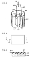
- An apparatus of FIG. 1 comprises: a container 101 made of an alkali-proof material for accommodating an article comprising a metal-resin joint; an alkaline solution 102 contained in the container 101; a counter electrode 103 immersed in the alkaline solution 102; a power source 104; a holding member 105 for holding the article comprising a metal-resin joint; a connecting member 106 for electrically connecting one terminal of the power source 104 with the metal portion of the article comprising a metal-resin joint; and a connecting member 107 for electrically connecting the other terminal of the power source 104 with the counter electrode 103.
- the container 101 made of an alkali-proof material for example, a beaker made of tetrafluoroethylene, is preferably used.
- the electrode used as the counter electrode 103 preferably comprises a nickel material.
- hydrogen and oxygen are produced at the article comprising a metal-resin joint and the counter electrode 103, respectively, which results in formation of a mist of the alkaline solution. Therefore, it is desirable for the apparatus to further comprise an exhaust facility, a facility for removing the alkali from the exhaust, a hydrogen-gas treating system, and the like.
- the electrolysis of water causes a change in hydroxide-ion concentration of the alkaline solution 102. It is thus desirable to control the concentration of the alkaline solution 102 by monitoring the specific gravity and pH of the alkaline solution 102 during the operation of the apparatus.
- a pinching member made of a conductive material, such as a clip may be used as the holding member 105.
- the metal-resin joint of the article can be immersed in the alkaline solution 102. In such a state, a voltage may be applied between the pinching member and the counter electrode.
- the article comprising a metal-resin joint is small, or if a large number of articles are treated at one time, it is preferable to use as the holding member 105 a container comprising a conductive perforated material such as a metal net 201 as illustrated in FIG. 2 . Then, with an article comprising a metal-resin joint placed in this container, a voltage may be applied between the container and the counter electrode. Also, by stirring articles comprising a metal-resin joint in the container with a stirring stick, a large number of articles can be separated into metal and resin at one time.
- the apparatus is preferably provided with means for applying heat or ultrasonic vibration to the article comprising a metal-resin joint directly or indirectly through the container 101 comprising an alkali-proof material, the alkaline solution 102, the holding member 105, or the like.
- means for applying heat or ultrasonic vibration to the article comprising a metal-resin joint directly or indirectly through the container 101 comprising an alkali-proof material, the alkaline solution 102, the holding member 105, or the like For example, it is effective to use the container 101 or the holding member 105 equipped with an ultrasonic transducer. It is also effective to provide means for applying peeling stress to the metal-resin joint.
- the potential applied to the article comprising a metal-resin joint can be checked by detecting the generation of hydrogen at the metal portion of the article. Specifically, if the generation of oxygen is detected, it is thought that the potential applied to the article comprising a metal-resin joint is for example in the range of -1.8 V to -1 V relative to the standard hydrogen electrode. It is desirable, however, to use an apparatus that is capable of controlling the potential while checking with a monitor the voltage and the current applied between the counter electrode and the article comprising a metal-resin joint.
- the power source 104 is desirably a direct current power source, and the power source is preferably capable of generating a voltage of 1.2 V or higher and 3.0 V or lower. With respect to the value of the current flowing between the counter electrode and the article comprising a metal-resin joint, an extremely small current suffices in comparison with common facilities such as electroplating, although it varies depending on the size etc. of the apparatus.
- the alkaline solution will creep up to the holding member 105, the connecting member 106 and the connecting member 107 during the operation of the apparatus.
- the arrival of the alkaline solution at the power source may damage the power source.
- the creeping of the alkaline solution is particularly remarkable in the member that electrically connects the negative electrode terminal of the direct current power source with the metal portion of the metal-resin joint.
- the holding member 105 and the connecting member 106 are coated with an insulating oxide layer. That is, at least a part of the conductive material constituting the holding member 105 and/or at least a part of the conductive material constituting the connecting member 106 are coated with an insulating oxide layer.
- the oxide layer on the metal surface fuses with the insulating oxide layer, like glass lining and enamel (porcelain enamel). The interface of such a joint is highly unlikely to be invaded by the alkaline solution.
- insulating oxides such as glass to alkaline solution
- resins used for the insulating resin layer are those having good alkali resistance, for example, polyolefin such as polyethylene and polypropylene, polystyrene, epoxy resin, polyether, polyacetal, polycarbonate, and the like.
- a steel plate of 0.10 mm in thickness, 50 mm in length and 30 mm in width was prepared.
- An adhesive comprising a synthetic rubber dissolved in a solvent (quick-curing bond G17 manufactured by Konishi Co., Ltd.) was applied onto one side of this steel plate, and an acrylic plate of polymethyl methacrylate of 50 mm in length, 30 mm in width and 2 mm in thickness was placed thereon so as to cover the steel plate.
- five same samples 1a, 1b, ... 1e having a joint of a steel plate and an acrylic plate were obtained.
- the part of the cathode-side lead about 1 cm away from the clip was covered with an insulating oxide layer of 5 mm in length and 0.2 mm in thickness, and the insulating oxide layer was further covered with an insulating resin layer of 0.5 mm in thickness.
- the insulating oxide layer was made of glass lining comprising SiO 2 (30 wt%), B 2 O 3 (20.5 wt%), Na 2 O (15.0 wt%) and CaF 2 (12.5 wt%), while the insulating resin layer was composed of epoxy resin.
- the sample 1a was pinched by the cathode-side clip, and the sample 1a was almost entirely immersed in the beaker 2a. Then, with the sample 1a as a cathode and the counter electrode as an anode, a voltage was applied at room temperature between them such that a current of 10 mA flew.
- FIG. 3 shows a state of the apparatus through which the current is passed.
- a beaker 301 is almost filled with an aqueous solution of sodium hydroxide 302 of 0.01 M, and a reference electrode (mercury/mercury oxide electrode) 310 is immersed in the aqueous solution of sodium hydroxide 302.
- a counter electrode 303 is entirely immersed in the aqueous solution of sodium hydroxide 302, and a sample 308 is also immersed entirely in the aqueous solution of sodium hydroxide 302 so as to face the counter electrode 303.
- a positive electrode terminal of a direct current power source 304 is connected to the counter electrode 303 by a lead 307, while a negative electrode terminal of the direct current power source 304 is connected to the sample 308 by a lead 306.
- the lead 306 is provided with a coated portion 309 covered with an insulating oxide layer and an insulating resin layer.
- a test was continued for a total of 8 hours while checking the presence and absence of separation at the joint of the steel plate and the acrylic plate of the sample 1a every 30 minutes after the supply of the current. Also, the potential of the metal portion of the sample 1a relative to a standard hydrogen electrode 10 minutes after the supply of the current was obtained from the potential measured using the reference electrode and the pH of the aqueous solution of sodium hydroxide.
- the potential E 0 of the mercury/mercury oxide electrode relative to the standard hydrogen electrode is expressed as a function of pH.
- Table 1 shows the measurement results of the time required to complete separation in the sample 1a and the potential of the metal portion of the sample 1a relative to the standard hydrogen electrode. Further, by performing the same operations as the above except for the use of the sample 1b and the beaker 2b, the sample 1c and the beaker 2c .., the times required to complete separation in the samples 1b to 1e and the potentials of the metal portions of the samples 1b to 1e relative to the standard hydrogen electrode were measured. The results are shown in Table 1.
- Table 1 Sample Potential of metal portion relative to standard hydrogen electrode (V) Time required to complete separation (h) 1a -1.65 >8 1b -1.35 6 1c -1.20 5.5 1d -1.23 4 1e -1.25 7
- Table 1 shows that the sample 1d exhibited the earliest separation, followed by 1c, 1b and 1e in this order. The sample 1a did not exhibit separation within 8 hours. From this, it has been made clear that the hydroxide-ion concentration of the alkaline solution is adequately 0.1 M or higher and 15 M or lower and optimally around 3 to 7 M.
- Table 2 shows the results together with the potentials of the metal portions of the samples relative to the standard hydrogen electrode.
- the potential of the metal portion of the sample relative to the standard hydrogen electrode is around - 1.8 to -1 V. Since the value of the current to be passed is dependent on the size of the sample to be separated, it is considered optimal to set the value of the current such that the potential of the metal portion of the sample is -1.8 to -1 V relative to the standard hydrogen electrode.
- the bath temperatures were set at 25°C, 45°C and 65°C, respectively, and the same separation tests as that of Example 1 were performed.
- the beaker was immersed in water of 25°C in an ultrasonic washing machine (40 kHz, output 200 W), and the same separation test as that of Example 1 was performed.
- FIG. 4 is a plane view thereof. Also, FIG. 5 is a cross-sectional view taken on line I-I of FIG. 4 .
- an adhesive comprising a synthetic rubber dissolved in a solvent (quick-curing bond G17 manufactured by Konishi Co., Ltd.) was applied onto the face of an acrylic plate 503 on the opposite side of the joint of the acrylic plate 503 and the steel plate 401, and a copper piece 504 of approximately 200 g was bonded thereto.
- test apparatus was arranged as illustrated in FIG. 6 .
- the ear part 402 of the sample was pinched by a clip 605 of the apparatus, and a weight 606 of approximately 100 g was connected to the clip 605 by a string supported by two pulleys 607.
- This sample was immersed in an aqueous solution of sodium hydroxide 302, as illustrated in FIG. 6 .
- a beaker 301 was immersed in a hot water bath of 25°C.
- peeling stress was applied to the metal-resin joint by the gravities applied to the weight 606 and the copper piece 504.
- a current of 10 mA between the counter electrode 303 and the copper plate 401 during the application of the peeling stress, the same separation test as that of Example 1 was performed.
- Table 3 shows the measurement results of the times required to complete separation and the potentials of the metal portions relative to the standard hydrogen electrode in the respective tests.
- Wires (0.5 mm in diameter and 50 mm in length) made of aluminum, titanium, chromium, manganese, iron, cobalt, nickel, copper, zinc, molybdenum, rhodium, palladium, silver, rhenium, osmium, iridium, platinum, gold, tin, lead or mercury amalgam (for use in decayed teeth treatment, Ag: 35 wt%, Sn: 15 wt%, Hg: 50 wt%) were prepared.
- varnish 702 for tubes was applied onto the surface of a wire 701 over a length of 40 mm.
- varnish comprising polyester resin diluted with styrene was used. The application was performed so as to expose the metal at the upper end part 10 mm and the bottom cross-section of the wire.
- Example 2 Separation tests almost the same as that of Example 1 were performed, using the same apparatus as that of Example 1 except for the use of these wires coated with the varnish.
- the wire coated with the varnish and a nickel plate were immersed in 50 ml of an aqueous solution of sodium hydroxide (6M) contained in a 100 ml beaker made of tetrafluoroethylene.
- 6M sodium hydroxide
- a current of 2 mA was passed between the upper end part of the wire and the nickel plate such that the wire served as a cathode.
- the potential of each wire relative to the standard hydrogen electrode and the time required for the vanish to separate from the wire were obtained. Table 4 shows the results.
- Example 1 The same apparatuses as that of the test apparatuses of the sample 1d of Example 1 were assembled except that samples were prepared using a polyvinyl chloride plate instead of the acrylic plate and using various adhesives as listed in Table 5 instead of the adhesive comprising a synthetic rubber dissolved in a solvent (quick-curing bond G17 manufactured by Konishi Co., Ltd.). And, by passing a current of 10 mA between the counter electrode and the steel plate such that the counter electrode served as an anode, separation tests of the metal-resin joints were performed in the same manner as in Example 1. Table 5 shows the kinds of the adhesives and their main components, the potentials of the metal portions of the samples relative to the standard hydrogen electrode, and the times required to complete separation.
- Table 5 shows the kinds of the adhesives and their main components, the potentials of the metal portions of the samples relative to the standard hydrogen electrode, and the times required to complete separation.
- Adhesive Main component of adhesive Potential of metal portion relative to standard hydrogen electrode (V) Time required to complete separation (h) Woodworking bond of Konishi Co., Ltd. Poly vinyl acetate emulsion -1.21 1 Quick-curing bond G17 of Konishi Co., Ltd. Synthetic rubber -1.23 3.5 G103 of Konishi Co., Ltd. Nitrile rubber -1.22 1.5 Araldite of Ciba-Geigy Epoxy resin -1.24 3 Aron alpha of Konishi Co., Ltd. Polycyanoacrylate -1.25 3.5 Super-X excel sigma (for vinyl) of Cemedine Co., Ltd. polyvinyl chloride 1.24 4
- the present invention makes it possible to easily separate/segregate the metal-resin joints of the articles comprising various metal-resin joints.
- the present invention can separate a metal-resin joint of an article in an inexpensive and simple manner without requiring a large amount of energy. Accordingly, articles comprising a metal-resin joint can be readily separated into their respective constituent materials, so that material recycling is facilitated.
Landscapes
- Engineering & Computer Science (AREA)
- Chemical & Material Sciences (AREA)
- Materials Engineering (AREA)
- Mechanical Engineering (AREA)
- Chemical Kinetics & Catalysis (AREA)
- Electrochemistry (AREA)
- Environmental & Geological Engineering (AREA)
- Metallurgy (AREA)
- Organic Chemistry (AREA)
- Separation, Recovery Or Treatment Of Waste Materials Containing Plastics (AREA)
- Water Treatment By Electricity Or Magnetism (AREA)
- Lining Or Joining Of Plastics Or The Like (AREA)
- Injection Moulding Of Plastics Or The Like (AREA)
- Moulds For Moulding Plastics Or The Like (AREA)
- Processing Of Solid Wastes (AREA)
Claims (14)
- Procédé de séparation d'un joint en résine et en métal comprenant les étapes consistant à :(1) immerger un article comprenant un joint en résine et en métal avec une contre électrode dans une solution alcaline, et(2) appliquer une tension sur une certaine période de temps entre la portion métallique dudit joint et ladite contre électrode de telle manière que le potentiel de ladite portion métallique est -2V ou plus et -0,6V ou moins par rapport à une électrode à hydrogène standard.
- Procédé de séparation d'un joint en résine et en métal selon la revendication 1, dans lequel ladite solution alcaline a une concentration en ions hydroxyde de 0,1 M ou plus et de 15 M ou moins et contient des cations métalliques alcalins.
- Procédé de séparation d'un joint en résine et en métal selon la revendication 1, dans lequel ladite solution alcaline a une concentration en ions hydroxyde de 3 M ou plus et de 7 M ou moins et contient des cations métalliques alcalins.
- Procédé de séparation d'un joint en résine et en métal selon la revendication 1, dans lequel ladite solution alcaline a une température de 0°C ou plus et de 80°C ou moins.
- Procédé de séparation d'un joint en résine et en métal selon la revendication 1, dans lequel ladite étape (2) comprend une application de vibration ultrasonore audit joint.
- Procédé de séparation d'un joint en résine et en métal selon la revendication 1, dans lequel ladite étape (2) comprend une application d'une contrainte de pelage audit joint.
- Procédé de séparation d'un joint en résine et en métal selon la revendication 1, dans lequel ladite portion métallique comprend un ou plusieurs éléments choisis dans le groupe constitué par Al, Ti, Cr, Mn, Fe, Co, Ni, Cu, Zn, Mo, Rh, Pd, Ag, Sn, Re, Os, Ir, Pt, Au, Hg et Pb.
- Procédé de séparation d'un joint en résine et en métal selon la revendication 1, dans lequel ladite portion de résine dudit joint en comprend une ou plusieurs choisies dans le groupe constitué par une polyoléfine, un polyamide, un polyester, un polyacétal, un polycarbonate, un éther polyarylénique, un sulfure de polyarylène, une polysulfone, une polyéthercétone, un polyimide, un polymère contenant du fluore, du caoutchouc naturel, une résine de phénol, du polyuréthane, une résine de silicone et une résine époxy.
- Procédé de séparation d'un joint en résine et en métal selon la revendication 1, dans lequel ledit joint est formé par (i) application d'un matériau de résine sur un article métallique, (ii) moulage par injection d'un matériau de résine sur un article métallique, ou (iii) liaison d'un métal et d'un matériau de résine par vulcanisation.
- Procédé de séparation d'un joint en résine et en métal selon la revendication 1, dans lequel la portion métallique et la portion de résine dudit joint sont liées avec un adhésif ou une bande adhésive, et ledit adhésif ou bande adhésive comprend un ou plusieurs éléments choisis dans le groupe constitué par une résine d'acétate de vinyle, une résine acrylique, un caoutchouc synthétique, un caoutchouc de nitrure, une résine époxy, une résine de cyanoacrylate et une résine de poly(chlorure de vinyle).
- Procédé de recyclage d'un article à jeter comprenant le procédé de la revendication 1, et comprenant les étapes consistant à :(1) récupérer un article à jeter comprenant un joint en résine et en métal,(2) immerger ledit joint et une contre électrode dans une solution alcaline,(2) séparer la portion de résine de la portion métallique en appliquant une tension sur une certaine période de temps entre la portion métallique dudit joint et ladite contre électrode de telle manière que le potentiel de ladite portion métallique est -2V ou plus et -0,6V ou moins par rapport à une électrode à hydrogène standard, et(4) ségréger la portion de résine séparée et ledit article à jeter à partir duquel la portion de résine a été séparée.
- Appareil pour séparer un joint en résine et en métal comprenant :(a) un récipient réalisé en un matériau résistant aux alcalins pour recevoir un article comprenant un joint en résine et en métal,(b) une solution alcaline contenue dans ledit récipient,(c) une contre électrode immergée dans ladite solution alcaline,(d) une source de puissance,(e) un organe de connexion A pour connecter électriquement une borne de ladite source de puissance avec la portion métallique dudit joint dudit article comprenant le joint en résine et en métal,(f) un organe de connexion B pour connecter électriquement l'autre borne de ladite source de puissance avec ladite contre électrode,(g) un moyen de mesure pour mesurer le potentiel de ladite portion métallique, et(h) un moyen de commande pour commander la tension appliquée entre ladite portion métallique et ladite contre électrode de telle manière que le potentiel de ladite portion métallique mesurée par ledit moyen de mesure est -2V ou plus et -0,6V ou moins par rapport à une électrode à hydrogène standard.
- Appareil pour séparer un joint en résine et en métal selon la revendication 12, dans lequel ledit organe conducteur A comprend un matériau conducteur, et une portion dudit matériau conducteur est revêtue d'une couche d'oxyde isolante.
- Appareil pour séparer un joint en résine et en métal selon la revendication 13, dans lequel ladite couche d'oxyde isolante est revêtue avec une couche de résine isolante.
Applications Claiming Priority (3)
| Application Number | Priority Date | Filing Date | Title |
|---|---|---|---|
| JP2002142146 | 2002-05-16 | ||
| JP2002142146 | 2002-05-16 | ||
| PCT/JP2003/005312 WO2003097317A1 (fr) | 2002-05-16 | 2003-04-24 | Procede et appareil de liberation d'un joint metal-resine |
Publications (3)
| Publication Number | Publication Date |
|---|---|
| EP1491310A1 EP1491310A1 (fr) | 2004-12-29 |
| EP1491310A4 EP1491310A4 (fr) | 2005-06-22 |
| EP1491310B1 true EP1491310B1 (fr) | 2009-07-01 |
Family
ID=29544975
Family Applications (1)
| Application Number | Title | Priority Date | Filing Date |
|---|---|---|---|
| EP20030725672 Expired - Lifetime EP1491310B1 (fr) | 2002-05-16 | 2003-04-24 | Procede et appareil de liberation d'un joint metal-resine |
Country Status (7)
| Country | Link |
|---|---|
| US (1) | US7431819B2 (fr) |
| EP (1) | EP1491310B1 (fr) |
| CN (1) | CN100425418C (fr) |
| AT (1) | ATE435105T1 (fr) |
| AU (1) | AU2003231504A1 (fr) |
| DE (1) | DE60328173D1 (fr) |
| WO (1) | WO2003097317A1 (fr) |
Families Citing this family (9)
| Publication number | Priority date | Publication date | Assignee | Title |
|---|---|---|---|---|
| JP4523789B2 (ja) * | 2003-10-31 | 2010-08-11 | パナソニック株式会社 | 金属皮膜剥離装置および金属皮膜剥離方法 |
| US8241458B2 (en) * | 2004-11-01 | 2012-08-14 | Polytechnic Institute Of New York University | Methods and apparatus for modifying gel adhesion strength |
| US20080218709A1 (en) * | 2007-03-07 | 2008-09-11 | Asml Netherlands B.V. | Removal of deposition on an element of a lithographic apparatus |
| CN103397374B (zh) * | 2013-07-29 | 2016-02-03 | 无锡商业职业技术学院 | 一种陶瓷电容内部镍电极剥离的方法 |
| CN104313677B (zh) * | 2014-10-08 | 2016-08-24 | 兰州飞行控制有限责任公司 | 一种去除带有镀铑层零件上黄膜的方法 |
| CN106929906A (zh) * | 2015-12-30 | 2017-07-07 | 中国建材国际工程集团有限公司 | 去除透明导电氧化物的方法 |
| CN108190887B (zh) * | 2017-12-28 | 2021-06-08 | 广州福之源环保科技有限公司 | 一种资源化利用废弃线路板上环氧树脂的方法 |
| CN110553882A (zh) * | 2018-06-01 | 2019-12-10 | 深圳市裕展精密科技有限公司 | 样品分离方法 |
| US20260048580A1 (en) * | 2022-08-22 | 2026-02-19 | Ohio State Innovation Foundation | Methods and systems for electrochemical polymers delamination |
Family Cites Families (24)
| Publication number | Priority date | Publication date | Assignee | Title |
|---|---|---|---|---|
| US2416294A (en) * | 1943-02-02 | 1947-02-25 | Little Inc A | Method of polishing metal surfaces |
| US2480845A (en) * | 1947-03-14 | 1949-09-06 | Frager Max | Electrolytic removal of resin from metal |
| BE634457A (fr) * | 1963-06-28 | |||
| US3575829A (en) * | 1968-08-14 | 1971-04-20 | Allegheny Ludlum Steel | System for cleaning contact rolls in a plating tank |
| DE2347108C3 (de) * | 1973-09-19 | 1980-02-14 | Vereinigte Aluminium-Werke Ag, 5300 Bonn | Verfahren zur Trennung von Metall und Kunststoff |
| US4020992A (en) * | 1975-11-20 | 1977-05-03 | Aluminum Company Of America | Separation of joined plastic and metal components |
| JPS537504A (en) * | 1976-07-09 | 1978-01-24 | Bridgestone Corp | Separating method for metallic material from composite body consisting of metallic material and electrically nonconductive material |
| US4406411A (en) * | 1979-09-10 | 1983-09-27 | Ford Motor Company | Reclamation and rejuvenation of plastic and metal from metallized plastic |
| CN1066413A (zh) * | 1992-05-05 | 1992-11-25 | 李金钟 | 复合铝塑(料)分离回收铝及塑料工艺及设备 |
| JPH06166769A (ja) | 1992-09-30 | 1994-06-14 | Shiroki Corp | 金属と樹脂の剥離方法及び剥離装置 |
| US5306349A (en) * | 1992-11-23 | 1994-04-26 | Sony Music Entertainment, Inc. | Method for removing coatings from compact discs |
| US5507926A (en) * | 1994-07-11 | 1996-04-16 | Emec Consultants | Electrolytically assisted paint removal from a metal substrate |
| TW277019B (fr) * | 1994-11-29 | 1996-06-01 | Gen Electric | |
| JPH08155388A (ja) | 1994-11-30 | 1996-06-18 | Showa Electric Wire & Cable Co Ltd | 耐熱塗装材および耐熱絶縁電線 |
| JPH08327512A (ja) | 1995-06-01 | 1996-12-13 | Kawasaki Steel Corp | 樹脂被覆鋼板の樹脂膜剥離液および樹脂膜剥離方法 |
| JPH09187751A (ja) | 1996-01-11 | 1997-07-22 | Matsushita Electric Ind Co Ltd | プリント基板の処理方法 |
| DE19606415A1 (de) * | 1996-02-21 | 1997-08-28 | Deutz Ag | Effektive Kunststoffsortierung |
| JPH09271748A (ja) * | 1996-04-09 | 1997-10-21 | Matsushita Electric Ind Co Ltd | プリント基板の処理方法 |
| US6045686A (en) * | 1997-03-18 | 2000-04-04 | The University Of Connecticut | Method and apparatus for electrochemical delacquering and detinning |
| JP2000037622A (ja) * | 1998-05-20 | 2000-02-08 | Kobe Steel Ltd | 接合体の分離方法及び分離装置 |
| US6436276B1 (en) * | 1999-10-07 | 2002-08-20 | Polyclad Laminates, Inc. | Cathodic photoresist stripping process |
| JP2001164400A (ja) * | 1999-12-03 | 2001-06-19 | Nippon Hyomen Kagaku Kk | フェノール樹脂用電解剥離液及び電解剥離方法 |
| JP2001316872A (ja) | 2000-05-10 | 2001-11-16 | Kunio Mori | 導電性金属についての表面機能化の方法 |
| JP2001334248A (ja) | 2000-05-29 | 2001-12-04 | Shimamura Biimu:Kk | 自動車安全ガラスにおける樹脂を狭着した一対のガラス板の剥離方法及び樹脂溶解方法 |
-
2003
- 2003-04-24 AU AU2003231504A patent/AU2003231504A1/en not_active Abandoned
- 2003-04-24 DE DE60328173T patent/DE60328173D1/de not_active Expired - Lifetime
- 2003-04-24 CN CNB038109891A patent/CN100425418C/zh not_active Expired - Fee Related
- 2003-04-24 AT AT03725672T patent/ATE435105T1/de not_active IP Right Cessation
- 2003-04-24 US US10/513,966 patent/US7431819B2/en not_active Expired - Fee Related
- 2003-04-24 EP EP20030725672 patent/EP1491310B1/fr not_active Expired - Lifetime
- 2003-04-24 WO PCT/JP2003/005312 patent/WO2003097317A1/fr not_active Ceased
Also Published As
| Publication number | Publication date |
|---|---|
| WO2003097317A1 (fr) | 2003-11-27 |
| AU2003231504A1 (en) | 2003-12-02 |
| US7431819B2 (en) | 2008-10-07 |
| CN100425418C (zh) | 2008-10-15 |
| US20050155205A1 (en) | 2005-07-21 |
| EP1491310A1 (fr) | 2004-12-29 |
| CN1652912A (zh) | 2005-08-10 |
| ATE435105T1 (de) | 2009-07-15 |
| DE60328173D1 (de) | 2009-08-13 |
| EP1491310A4 (fr) | 2005-06-22 |
Similar Documents
| Publication | Publication Date | Title |
|---|---|---|
| EP1491310B1 (fr) | Procede et appareil de liberation d'un joint metal-resine | |
| EP1043408B1 (fr) | Procédés de récuperation et d'enlèvement du cuivre contenus dans des solutions | |
| EP2461357A2 (fr) | Composite en résine métallique, procédé de production associé, barre de bus, boîtier de module et pièce de connecteur en résine | |
| KR950032718A (ko) | 구리 호일용 결절상 구리/니켈 합금 처리법 | |
| JP5275701B2 (ja) | プリント配線基板用アルミニウム材及びその製造方法 | |
| HK71687A (en) | Electrochemical treatment of metal sheet or foil for improving its bond strength | |
| KR102098576B1 (ko) | 표면처리 알루미늄재 및 그 제조방법과 수지 피복 표면처리 알루미늄재 | |
| ATE152858T1 (de) | Stromableiter für elektrochemischen sicherheits- generatoren, verfahren zur herstellung, und daraus erhaltene generatoren | |
| KR100883726B1 (ko) | 부도체 제품의 도금방법 | |
| JP4991078B2 (ja) | 過マンガン酸塩エッチング溶液の電気化学再生用のカソード、該カソードの製造方法及び該カソードを有する装置 | |
| US6176985B1 (en) | Laminated electroplating rack and connection system for optimized plating | |
| KR20040057979A (ko) | 무연 주석합금을 피복하는 방법 | |
| US3629007A (en) | Reserve battery electrodes using bonded active materials | |
| EP1420620A2 (fr) | Procédé de décrassage et de texturation | |
| JP4167117B2 (ja) | 金属−樹脂接合部の剥離方法および剥離装置 | |
| KR101029821B1 (ko) | 이차전지용 양극단자의 제조 방법 | |
| JP2008516088A (ja) | 電気メッキする非導電性基板の処理方法 | |
| CN109075150A (zh) | 引线框结构,引线框式表面粘着型电子装置及其制造方法 | |
| JP5837681B2 (ja) | 物品からの金属の再生 | |
| US4364800A (en) | Situ metal plating of the cathode terminal surface of an electrochemical cell | |
| JP3133071U (ja) | 燃料電池の集電板 | |
| Baker et al. | Structural Bonding of Polyolefins | |
| JP5518421B2 (ja) | ニッケルめっきが施された銅又は銅合金屑のリサイクル方法 | |
| JP2005307270A (ja) | キャリア箔付電解銅箔及びそのキャリア箔付電解銅箔の製造方法 | |
| WO2000061365A1 (fr) | Materiau composite au titane |
Legal Events
| Date | Code | Title | Description |
|---|---|---|---|
| PUAI | Public reference made under article 153(3) epc to a published international application that has entered the european phase |
Free format text: ORIGINAL CODE: 0009012 |
|
| 17P | Request for examination filed |
Effective date: 20041004 |
|
| AK | Designated contracting states |
Kind code of ref document: A1 Designated state(s): AT BE BG CH CY CZ DE DK EE ES FI FR GB GR HU IE IT LI LU MC NL PT RO SE SI SK TR |
|
| AX | Request for extension of the european patent |
Extension state: AL LT LV MK |
|
| A4 | Supplementary search report drawn up and despatched |
Effective date: 20050510 |
|
| RIC1 | Information provided on ipc code assigned before grant |
Ipc: 7B 29B 17/02 A Ipc: 7C 08J 11/06 B Ipc: 7B 09B 3/00 B Ipc: 7C 25F 5/00 B Ipc: 7B 29B 17/00 B Ipc: 7C 25F 1/02 B |
|
| DAX | Request for extension of the european patent (deleted) | ||
| 17Q | First examination report despatched |
Effective date: 20071213 |
|
| RAP1 | Party data changed (applicant data changed or rights of an application transferred) |
Owner name: PANASONIC CORPORATION |
|
| GRAP | Despatch of communication of intention to grant a patent |
Free format text: ORIGINAL CODE: EPIDOSNIGR1 |
|
| GRAS | Grant fee paid |
Free format text: ORIGINAL CODE: EPIDOSNIGR3 |
|
| GRAA | (expected) grant |
Free format text: ORIGINAL CODE: 0009210 |
|
| AK | Designated contracting states |
Kind code of ref document: B1 Designated state(s): AT BE BG CH CY CZ DE DK EE ES FI FR GB GR HU IE IT LI LU MC NL PT RO SE SI SK TR |
|
| REG | Reference to a national code |
Ref country code: GB Ref legal event code: FG4D |
|
| REG | Reference to a national code |
Ref country code: CH Ref legal event code: EP |
|
| REG | Reference to a national code |
Ref country code: IE Ref legal event code: FG4D |
|
| REF | Corresponds to: |
Ref document number: 60328173 Country of ref document: DE Date of ref document: 20090813 Kind code of ref document: P |
|
| PG25 | Lapsed in a contracting state [announced via postgrant information from national office to epo] |
Ref country code: SI Free format text: LAPSE BECAUSE OF FAILURE TO SUBMIT A TRANSLATION OF THE DESCRIPTION OR TO PAY THE FEE WITHIN THE PRESCRIBED TIME-LIMIT Effective date: 20090701 |
|
| NLV1 | Nl: lapsed or annulled due to failure to fulfill the requirements of art. 29p and 29m of the patents act | ||
| PG25 | Lapsed in a contracting state [announced via postgrant information from national office to epo] |
Ref country code: EE Free format text: LAPSE BECAUSE OF FAILURE TO SUBMIT A TRANSLATION OF THE DESCRIPTION OR TO PAY THE FEE WITHIN THE PRESCRIBED TIME-LIMIT Effective date: 20090701 Ref country code: AT Free format text: LAPSE BECAUSE OF FAILURE TO SUBMIT A TRANSLATION OF THE DESCRIPTION OR TO PAY THE FEE WITHIN THE PRESCRIBED TIME-LIMIT Effective date: 20090701 Ref country code: SE Free format text: LAPSE BECAUSE OF FAILURE TO SUBMIT A TRANSLATION OF THE DESCRIPTION OR TO PAY THE FEE WITHIN THE PRESCRIBED TIME-LIMIT Effective date: 20090701 Ref country code: ES Free format text: LAPSE BECAUSE OF FAILURE TO SUBMIT A TRANSLATION OF THE DESCRIPTION OR TO PAY THE FEE WITHIN THE PRESCRIBED TIME-LIMIT Effective date: 20091012 Ref country code: FI Free format text: LAPSE BECAUSE OF FAILURE TO SUBMIT A TRANSLATION OF THE DESCRIPTION OR TO PAY THE FEE WITHIN THE PRESCRIBED TIME-LIMIT Effective date: 20090701 |
|
| PG25 | Lapsed in a contracting state [announced via postgrant information from national office to epo] |
Ref country code: NL Free format text: LAPSE BECAUSE OF FAILURE TO SUBMIT A TRANSLATION OF THE DESCRIPTION OR TO PAY THE FEE WITHIN THE PRESCRIBED TIME-LIMIT Effective date: 20090701 |
|
| PG25 | Lapsed in a contracting state [announced via postgrant information from national office to epo] |
Ref country code: BG Free format text: LAPSE BECAUSE OF FAILURE TO SUBMIT A TRANSLATION OF THE DESCRIPTION OR TO PAY THE FEE WITHIN THE PRESCRIBED TIME-LIMIT Effective date: 20091001 Ref country code: PT Free format text: LAPSE BECAUSE OF FAILURE TO SUBMIT A TRANSLATION OF THE DESCRIPTION OR TO PAY THE FEE WITHIN THE PRESCRIBED TIME-LIMIT Effective date: 20091102 |
|
| PG25 | Lapsed in a contracting state [announced via postgrant information from national office to epo] |
Ref country code: RO Free format text: LAPSE BECAUSE OF FAILURE TO SUBMIT A TRANSLATION OF THE DESCRIPTION OR TO PAY THE FEE WITHIN THE PRESCRIBED TIME-LIMIT Effective date: 20090701 Ref country code: CZ Free format text: LAPSE BECAUSE OF FAILURE TO SUBMIT A TRANSLATION OF THE DESCRIPTION OR TO PAY THE FEE WITHIN THE PRESCRIBED TIME-LIMIT Effective date: 20090701 Ref country code: DK Free format text: LAPSE BECAUSE OF FAILURE TO SUBMIT A TRANSLATION OF THE DESCRIPTION OR TO PAY THE FEE WITHIN THE PRESCRIBED TIME-LIMIT Effective date: 20090701 |
|
| PLBE | No opposition filed within time limit |
Free format text: ORIGINAL CODE: 0009261 |
|
| STAA | Information on the status of an ep patent application or granted ep patent |
Free format text: STATUS: NO OPPOSITION FILED WITHIN TIME LIMIT |
|
| PG25 | Lapsed in a contracting state [announced via postgrant information from national office to epo] |
Ref country code: BE Free format text: LAPSE BECAUSE OF FAILURE TO SUBMIT A TRANSLATION OF THE DESCRIPTION OR TO PAY THE FEE WITHIN THE PRESCRIBED TIME-LIMIT Effective date: 20090701 Ref country code: SK Free format text: LAPSE BECAUSE OF FAILURE TO SUBMIT A TRANSLATION OF THE DESCRIPTION OR TO PAY THE FEE WITHIN THE PRESCRIBED TIME-LIMIT Effective date: 20090701 |
|
| 26N | No opposition filed |
Effective date: 20100406 |
|
| PG25 | Lapsed in a contracting state [announced via postgrant information from national office to epo] |
Ref country code: GR Free format text: LAPSE BECAUSE OF FAILURE TO SUBMIT A TRANSLATION OF THE DESCRIPTION OR TO PAY THE FEE WITHIN THE PRESCRIBED TIME-LIMIT Effective date: 20091002 |
|
| PG25 | Lapsed in a contracting state [announced via postgrant information from national office to epo] |
Ref country code: MC Free format text: LAPSE BECAUSE OF NON-PAYMENT OF DUE FEES Effective date: 20100430 |
|
| REG | Reference to a national code |
Ref country code: CH Ref legal event code: PL |
|
| PG25 | Lapsed in a contracting state [announced via postgrant information from national office to epo] |
Ref country code: IE Free format text: LAPSE BECAUSE OF NON-PAYMENT OF DUE FEES Effective date: 20100424 |
|
| PG25 | Lapsed in a contracting state [announced via postgrant information from national office to epo] |
Ref country code: CH Free format text: LAPSE BECAUSE OF NON-PAYMENT OF DUE FEES Effective date: 20100430 Ref country code: LI Free format text: LAPSE BECAUSE OF NON-PAYMENT OF DUE FEES Effective date: 20100430 |
|
| PG25 | Lapsed in a contracting state [announced via postgrant information from national office to epo] |
Ref country code: IT Free format text: LAPSE BECAUSE OF FAILURE TO SUBMIT A TRANSLATION OF THE DESCRIPTION OR TO PAY THE FEE WITHIN THE PRESCRIBED TIME-LIMIT Effective date: 20090701 |
|
| PGFP | Annual fee paid to national office [announced via postgrant information from national office to epo] |
Ref country code: DE Payment date: 20120502 Year of fee payment: 10 |
|
| PG25 | Lapsed in a contracting state [announced via postgrant information from national office to epo] |
Ref country code: CY Free format text: LAPSE BECAUSE OF FAILURE TO SUBMIT A TRANSLATION OF THE DESCRIPTION OR TO PAY THE FEE WITHIN THE PRESCRIBED TIME-LIMIT Effective date: 20090701 |
|
| PGFP | Annual fee paid to national office [announced via postgrant information from national office to epo] |
Ref country code: GB Payment date: 20120418 Year of fee payment: 10 Ref country code: FR Payment date: 20120504 Year of fee payment: 10 |
|
| PG25 | Lapsed in a contracting state [announced via postgrant information from national office to epo] |
Ref country code: LU Free format text: LAPSE BECAUSE OF NON-PAYMENT OF DUE FEES Effective date: 20100424 Ref country code: HU Free format text: LAPSE BECAUSE OF FAILURE TO SUBMIT A TRANSLATION OF THE DESCRIPTION OR TO PAY THE FEE WITHIN THE PRESCRIBED TIME-LIMIT Effective date: 20100102 |
|
| PG25 | Lapsed in a contracting state [announced via postgrant information from national office to epo] |
Ref country code: TR Free format text: LAPSE BECAUSE OF FAILURE TO SUBMIT A TRANSLATION OF THE DESCRIPTION OR TO PAY THE FEE WITHIN THE PRESCRIBED TIME-LIMIT Effective date: 20090701 |
|
| GBPC | Gb: european patent ceased through non-payment of renewal fee |
Effective date: 20130424 |
|
| PG25 | Lapsed in a contracting state [announced via postgrant information from national office to epo] |
Ref country code: GB Free format text: LAPSE BECAUSE OF NON-PAYMENT OF DUE FEES Effective date: 20130424 Ref country code: DE Free format text: LAPSE BECAUSE OF NON-PAYMENT OF DUE FEES Effective date: 20131101 |
|
| REG | Reference to a national code |
Ref country code: FR Ref legal event code: ST Effective date: 20131231 |
|
| REG | Reference to a national code |
Ref country code: DE Ref legal event code: R119 Ref document number: 60328173 Country of ref document: DE Effective date: 20131101 |
|
| PG25 | Lapsed in a contracting state [announced via postgrant information from national office to epo] |
Ref country code: FR Free format text: LAPSE BECAUSE OF NON-PAYMENT OF DUE FEES Effective date: 20130430 |