EP1491401A2 - Procédé et structure de positionnement d'un phare sur une carrosserie de véhicule - Google Patents
Procédé et structure de positionnement d'un phare sur une carrosserie de véhicule Download PDFInfo
- Publication number
- EP1491401A2 EP1491401A2 EP04013682A EP04013682A EP1491401A2 EP 1491401 A2 EP1491401 A2 EP 1491401A2 EP 04013682 A EP04013682 A EP 04013682A EP 04013682 A EP04013682 A EP 04013682A EP 1491401 A2 EP1491401 A2 EP 1491401A2
- Authority
- EP
- European Patent Office
- Prior art keywords
- headlamp
- vehicle body
- positioning
- bracket
- fender
- Prior art date
- Legal status (The legal status is an assumption and is not a legal conclusion. Google has not performed a legal analysis and makes no representation as to the accuracy of the status listed.)
- Granted
Links
Images



Classifications
-
- B—PERFORMING OPERATIONS; TRANSPORTING
- B62—LAND VEHICLES FOR TRAVELLING OTHERWISE THAN ON RAILS
- B62D—MOTOR VEHICLES; TRAILERS
- B62D65/00—Designing, manufacturing, e.g. assembling, facilitating disassembly, or structurally modifying motor vehicles or trailers, not otherwise provided for
- B62D65/02—Joining sub-units or components to, or positioning sub-units or components with respect to, body shell or other sub-units or components
- B62D65/16—Joining sub-units or components to, or positioning sub-units or components with respect to, body shell or other sub-units or components the sub-units or components being exterior fittings, e.g. bumpers, lights, wipers, exhausts
-
- B—PERFORMING OPERATIONS; TRANSPORTING
- B60—VEHICLES IN GENERAL
- B60Q—ARRANGEMENT OF SIGNALLING OR LIGHTING DEVICES, THE MOUNTING OR SUPPORTING THEREOF OR CIRCUITS THEREFOR, FOR VEHICLES IN GENERAL
- B60Q1/00—Arrangement of optical signalling or lighting devices, the mounting or supporting thereof or circuits therefor
- B60Q1/02—Arrangement of optical signalling or lighting devices, the mounting or supporting thereof or circuits therefor the devices being primarily intended to illuminate the way ahead or to illuminate other areas of way or environments
- B60Q1/04—Arrangement of optical signalling or lighting devices, the mounting or supporting thereof or circuits therefor the devices being primarily intended to illuminate the way ahead or to illuminate other areas of way or environments the devices being headlights
- B60Q1/0408—Arrangement of optical signalling or lighting devices, the mounting or supporting thereof or circuits therefor the devices being primarily intended to illuminate the way ahead or to illuminate other areas of way or environments the devices being headlights built into the vehicle body, e.g. details concerning the mounting of the headlamps on the vehicle body
- B60Q1/0433—Arrangement of optical signalling or lighting devices, the mounting or supporting thereof or circuits therefor the devices being primarily intended to illuminate the way ahead or to illuminate other areas of way or environments the devices being headlights built into the vehicle body, e.g. details concerning the mounting of the headlamps on the vehicle body the housing being fastened onto the vehicle body using screws
-
- B—PERFORMING OPERATIONS; TRANSPORTING
- B60—VEHICLES IN GENERAL
- B60Q—ARRANGEMENT OF SIGNALLING OR LIGHTING DEVICES, THE MOUNTING OR SUPPORTING THEREOF OR CIRCUITS THEREFOR, FOR VEHICLES IN GENERAL
- B60Q1/00—Arrangement of optical signalling or lighting devices, the mounting or supporting thereof or circuits therefor
- B60Q1/02—Arrangement of optical signalling or lighting devices, the mounting or supporting thereof or circuits therefor the devices being primarily intended to illuminate the way ahead or to illuminate other areas of way or environments
- B60Q1/04—Arrangement of optical signalling or lighting devices, the mounting or supporting thereof or circuits therefor the devices being primarily intended to illuminate the way ahead or to illuminate other areas of way or environments the devices being headlights
- B60Q1/0408—Arrangement of optical signalling or lighting devices, the mounting or supporting thereof or circuits therefor the devices being primarily intended to illuminate the way ahead or to illuminate other areas of way or environments the devices being headlights built into the vehicle body, e.g. details concerning the mounting of the headlamps on the vehicle body
- B60Q1/0475—Arrangement of optical signalling or lighting devices, the mounting or supporting thereof or circuits therefor the devices being primarily intended to illuminate the way ahead or to illuminate other areas of way or environments the devices being headlights built into the vehicle body, e.g. details concerning the mounting of the headlamps on the vehicle body with provisions for pre-mounting, for temporary holding the headlamp before or during final mounting
Definitions
- the present invention relates to method and structure for positioning a headlamp on a front section of a vehicle body when assembling the vehicle body with the headlamp.
- a front end module which includes a radiator core support and other parts such as a bumper fascia is put together with a front section of the vehicle body. Automotive headlamps are attached to the radiator core support in the front end module.
- Japanese Patent Application Publication Laid-Open No. 2002-264745 discloses a structure, in which a bumper fascia provided with headlamp attachments, is put together with a front section of the vehicle body.
- the headlamps are fixed to the radiator core support, and the radiator core support is positioned on front fenders which are fixed to hood ridges in the front section of the vehicle body. Accordingly, it is difficult to adjust the alignment of the radiator core support, hood ridges, headlamps and front fenders. Misalignment thereof results in uneven gaps or steps formed on a surface, affecting the appearance of the front section of the vehicle body.
- An object of the present invention is to provide method and structure for properly positioning a headlamp on a front section of a vehicle body.
- An aspect of the present invention is a method for positioning a headlamp on a vehicle body, comprising: setting the headlamp temporarily in a first position on a first member of the vehicle body; and putting the first member and a second member of the vehicle body together, bringing the first member along with the headlamp closer to the second member, allowing the headlamp to move relative to the first member from the first position.
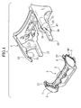
- a front end module 3 is put together with a front section of a vehicle main body 1.
- An assisting device or a robot with a mounting jig (not shown) for gripping the front end module 3 may be used for bringing the front end module 3 closer to the vehicle main body 1.
- the front end module 3 includes a radiator core support 5 which has lamp attachments 7 on upper portions of outer ends in a vehicle transverse direction thereof. Headlamps 9 are attached onto the lamp attachments 7 in a state of being held temporarily.
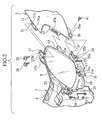
- FIG. 2 is a perspective view showing a left side of the front section of the vehicle main body 1 when the front end module 3 of FIG. 1 is brought close to the front section of the vehicle main body 1.
- a right side of the front section is symmetrical to the left side thereof. Description will be made only on this left side, and explanation of the right side will be omitted.
- a round bar-shaped pin 17 for temporally holding the headlamp 9 is formed to extend downward from a lower portion of the headlamp 9.
- a substantially horizontal planar portion 19 is formed on the radiator core support 5.
- a hole 21 is provided on the planer portion 19, a hole 21 is provided. The pin 17 is inserted into the hole 21 and temporarily held by the hole 21.
- These pin 17 and hole 21 constitute a temporarily holding device for the headlamp 9.
- the pin 17 is formed to have a groove portion 17b having a width larger than a plate thickness of the planar portion 19 on an outer circumferential surface thereof at a position apart from a tip portion (lower end) 17a by a predetermined distance. Moreover, the pin 17 is formed to have on the outer circumferential surface above the groove portion 17b, a disc flange 17c extending from the outer circumferential surface.
- the hole 21 is constituted of a rectangular opening 21a and a holder portion 21c provided on a rear side of the opening 21a. The holder portion 21c communicates with the opening 21a through a communicating portion 21b, and extends rearward therefrom.
- the holder portion 21c is an inner edge of the planar portion 19 formed in a semicircular shape, and an inner diameter thereof is set larger than an outer diameter of the groove portion 17b of the pin 17, and smaller than an outer diameter of a portion 17d above the groove portion 17b. Accordingly, if the groove portion 17b of the pin 17 is inserted into and engaged with the holder portion 21c, the headlamp 9 is temporarily held by the front end module 3.
- the communicating portion 21b is formed to have an opening width W1 somewhat smaller than the outer diameter of the groove portion 17b. This makes it difficult for the groove portion 17b in the holder portion 21c to move into the opening 21a through the communicating portion 21b. Thus, the headlamp 9 is not released easily from the temporal holding thereof.
- opening edges 21d of the communicating portion 21b are elastically deformed to some extent to allow the groove portion 17b to get through the communicating portion 21b.
- the temporarily held headlamp 9 is thus located in the rear of a normal attachment position thereof on the front end module 3, and is movable frontward relative to the front end module 3 while being kept in this state.
- the flange 17c of the pin 17 is formed larger than the opening 21a.
- the flange 17c is caught on the planar portion 19, preventing the headlamp 9 from falling beyond a limited extent.
- a front bracket 23 is formed on a front part of a transversely inner side of the headlamp 9.
- the radiator core support 5 is provided with a front headlamp bracket 25, which is located in front of the front bracket 23 of the temporarily held headlamp 9 at a predetermined interval.
- a front fixing bolt 26 is inserted into the front headlamp bracket 25 from the front, and a rear end of the front fixing bolt 26 is temporarily fastened to the front bracket 23.
- a rear bracket 27 On a rear part of the transversely inner side of the headlamp 9, a rear bracket 27 is provided which extends rearward. On this rear bracket 27, a bolt insertion hole 27a and a clip insertion hole 27b are made, into which a rear fixing bolt 28 and a clip 29 are respectively inserted.
- a rear headlamp bracket 31 formed with a bolt insertion hole 31a and a clip engagement hole 31b.
- a nut (not shown) is fixed for fastening the rear fixing bolt 28 thereto.
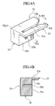
- FIG. 4A is an enlarged perspective view showing the fixing block 33.
- the fixing block 33 includes a block-shaped fender bracket 35, and a plate-shaped fender guide member 37 horizontally extending from an upper part of the fender bracket 35.
- a screw hole 35b is provided on a transversely outer side face 35a of the fender bracket 35.
- a lower bracket 39 is provided, on which a bolt insertion hole 39a is provided.
- a bolt 41 is inserted into the bolt insertion hole 39a, and is fastened to the screw hole 35b of the fixing block 33.
- the fender guide member 37 extends from the upper portion of the fender bracket 35 transversely outward and has a part extending rearward.
- a guide groove 37a is formed on the fender guide member 37 to extend frontward from a rear end thereof.
- the guide groove 37a is formed on a rear end thereof with a tapered notch 37b progressively widening rearward.
- An entrance 37d of the guide groove 37a opens with a width W2.
- the guide groove 37a receives and guides the lower bracket 39 of the front fender 13, which has a thickness t1. As shown in FIG. 4B, an inner sidewall 37c of the guide groove 37a and the side face 35a of the fender bracket 35 are set substantially flush with each other.
- the fender guide member 37 guides the front edge of the lower bracket 39 of the front fender 13 into the guide groove 37a, providing inner edges of the guide groove 37a as slidable on both transversely outer and inner sides of the vertically extending lower bracket 39.
- the headlamp 9 has a rear side face extending upward and rearward from a lower part thereof where the fixing block 33 is provided.
- a positioning pin 45 is provided to protrude rearward.
- the positioning pin 45 is tapered to have at a tip thereof a width W3 in the horizontal direction.
- a pin receiver 47 is provided, which is formed to protrude transversely inward from the front edge and to have an inclined face to be matched to the aforementioned rear side face of the headlamp 9.
- the positioning pin 45 is inserted into a positioning hole 47a with a horizontal width W4, provided on the pin receiver 47.
- the headlamp 9 is thus positioned on the vehicle main body 1.
- the headlamp 9 is temporarily held on the radiator core support 5.
- This temporal holding is achieved by inserting the temporarily holding pin 17 into the opening 21a of the hole 21, pushing the pin 17 rearward to have the groove portion 17b of the pin 17 fitted into the holder portion 21c, as shown in FIG. 3, and inserting the front fixing bolt 26 into the front headlamp bracket 25, and fastening the rear end of the front fixing bolt 26 temporarily to the front bracket 23 of the headlamp 9.
- the front end module 3, with the headlamp 9 temporarily held on the radiator core support 5, is moved from the position shown in FIG. 2, and brought closer to the front section of the vehicle main body 1.
- the front edge of the lower bracket 39 of the front fender 13 starts entering the guide groove 37b of the fender guide member 37 as shown in FIG. 6.
- the fender guide member 37 catches the front edge of the lower bracket 39 and guides the lower bracket 39 into the guide groove 37b with the inner edges thereof sliding on transversely inner and outer sides of the lower bracket 39.
- the notch 37b is formed at the entrance of the guide groove 37a, and accordingly, the lower bracket 39 can be easily guided to enter the guide groove 37a.
- the lower bracket 39 of the front fender 13 is guided into the guide groove 37a before the positioning pin 45 starts engagement with the positioning hole 47a, and the positioning pin 45 is tapered at its leading end. Accordingly, the positioning pin 45 can easily engage with the positioning hole 47a.
- the rear bracket 27 of the headlamp 9 is placed on the rear headlamp bracket 31 of the front fender 13.
- the bolt insertion holes 27a and 31a are aligned to be match with each other, and the clip insertion hole 27b and the clip engagement hole 31b are aligned to be match with each other.
- the headlamp 9 moves together with the vehicle main body 1, and accordingly the radiator core support 5 moves rearward relative to the headlamp 9.
- the temporarily holding pin 17 is detached from the holder portion 21c, and moves into the opening 21a.
- the temporal holding of the headlamp 9 is undone.
- the flange 17c of the pin 17 is brought into contact with a peripheral edge of the opening 21a, and prevents the headlamp 9 from falling beyond the limited extent.
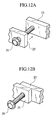
- the front headlamp bracket 25 provided on the radiator core support 5 moves further rearward relative to the headlamp 9. Motions in this case are shown in FIGS. 12A and 12B. Specifically, the front headlamp bracket 25 moves rearward from the position shown in FIG. 12A, then comes into contact with the front bracket 23 of the headlamp 9, as shown in FIG. 12B, with the front fixing bolt 26 protruding frontward from the front headlamp bracket 25.
- the front bracket 23 is fastened to the front headlamp bracket 25 of the radiator core support 5.
- the clip 29 is inserted into the clip insertion hole 27b, and the rear fixing bolt 28 is inserted into the bolt insertion hole 27a and tightened.
- the rear bracket 27 of the headlamp 9 is fastened to the rear headlamp bracket 31 of the front fender 13.
- the bolt 41 is inserted from transversely outer side into the bolt insertion hole 39a of the lower bracket 39 of the front fender 13, and screwed into the screw hole 35b of the fender bracket 35.
- the fixing block 33 of the headlamp 9 is fixed to the lower bracket 39, whereby the headlamp 9 is positioned on the front fender 13.
- the headlamp 9 is temporarily held on the radiator core support 5 in a position at the rear of the normal attachment position thereof relative to the front end module 3. Then, the front end module 3 is brought closer to the front section of the vehicle main body 1 from the front of the vehicle main body 1, to be put together with the front section. The head lamp 9 comes into contact with the front section of the vehicle main body 1 and is positioned on the front section, at a time when the front end module 3 is moved rearward. Thereafter, the headlamp 9 moves frontward relative to the radiator core support 5.
- the headlamp 9 Since the headlamp 9 is positioned on the front fender 13, affection of misalignments of the radiator core support 5, hood ridge 11, headlamp 9 and front fender 13 are eliminated.
- the headlamp 9 and the front fender 13 are aligned, and gaps and steps formed on a surface thereof can be even and smooth, improving the appearance of the front section of the vehicle body.
- the headlamp 9 can be securely positioned on the front fender 13 since the headlamp 9 is set movable relative to the front end module 3 in the state of being temporarily held.
- the headlamp 9 is incorporated in the front end module 3 while being temporarily held on the radiator core support 5. Accordingly, work of installing the headlamp 9 is eliminated, thus reducing the number of steps in the manufacturing process.
- allowable relative positional shift between the engaging positioning pin 45 and positioning hole 47a may be set smaller than that of the headlamp 9 and the front fender 13.
- a difference between the tip width W3 of the positioning pin 45 and the opening width W4 of the positioning hole 47a may be set smaller than a difference between the entrance width W2 of the guide groove 37a of the fender guide member 37 and the thickness tl of the lower bracket 39 of the front fender 13.
Landscapes
- Engineering & Computer Science (AREA)
- Mechanical Engineering (AREA)
- Manufacturing & Machinery (AREA)
- Chemical & Material Sciences (AREA)
- Combustion & Propulsion (AREA)
- Transportation (AREA)
- Lighting Device Outwards From Vehicle And Optical Signal (AREA)
- Body Structure For Vehicles (AREA)
Applications Claiming Priority (2)
| Application Number | Priority Date | Filing Date | Title |
|---|---|---|---|
| JP2003179551A JP3843968B2 (ja) | 2003-06-24 | 2003-06-24 | ヘッドランプの車体位置決め方法および車体位置決め構造 |
| JP2003179551 | 2003-06-24 |
Publications (3)
| Publication Number | Publication Date |
|---|---|
| EP1491401A2 true EP1491401A2 (fr) | 2004-12-29 |
| EP1491401A3 EP1491401A3 (fr) | 2005-11-30 |
| EP1491401B1 EP1491401B1 (fr) | 2008-09-10 |
Family
ID=33411057
Family Applications (1)
| Application Number | Title | Priority Date | Filing Date |
|---|---|---|---|
| EP04013682A Expired - Lifetime EP1491401B1 (fr) | 2003-06-24 | 2004-06-09 | Procédé et structure de positionnement d'un phare sur une carrosserie de véhicule |
Country Status (6)
| Country | Link |
|---|---|
| US (1) | US7338191B2 (fr) |
| EP (1) | EP1491401B1 (fr) |
| JP (1) | JP3843968B2 (fr) |
| KR (1) | KR100570719B1 (fr) |
| CN (1) | CN1313311C (fr) |
| DE (1) | DE602004016420D1 (fr) |
Cited By (17)
| Publication number | Priority date | Publication date | Assignee | Title |
|---|---|---|---|---|
| DE102006008240A1 (de) * | 2006-02-22 | 2007-08-23 | Volkswagen Ag | Befestigungsvorrichtung für einen Scheinwerfer an einem Fahrzeug |
| JP2007297041A (ja) * | 2006-05-05 | 2007-11-15 | Nissan Motor Manufacturing (Uk) Ltd | 車両のボディパネルの剛性の改善方法 |
| EP1939076A1 (fr) * | 2006-12-29 | 2008-07-02 | Automotive Lighting Italia Spa | Procédé de fabrication de phares pour un assemblage précis sur les véhicules |
| FR2921333A1 (fr) * | 2007-09-25 | 2009-03-27 | Peugeot Citroen Automobiles Sa | Vehicule automobile a jeux et affleurements reduits |
| FR2932437A1 (fr) * | 2008-06-17 | 2009-12-18 | Peugeot Citroen Automobiles Sa | Dispositif d'indexation d'un bloc optique sur un support adjacent de vehicule automobile |
| FR2933371A1 (fr) * | 2008-07-01 | 2010-01-08 | Renault Sas | Agencement pour une partie avant de vehicule automobile |
| FR2934557A1 (fr) * | 2008-08-04 | 2010-02-05 | Peugeot Citroen Automobiles Sa | Systeme d'indexage d'un organe eclairant sur un vehicule automobile. |
| GB2437719B (en) * | 2006-05-05 | 2010-12-29 | Nissan Motor Mfg | Body panel insert |
| FR2971466A1 (fr) * | 2011-02-14 | 2012-08-17 | Peugeot Citroen Automobiles Sa | Dispositif de montage et demontage simplifies d'au moins un projecteur de vehicule automobile |
| FR3038289A1 (fr) * | 2015-07-03 | 2017-01-06 | Peugeot Citroen Automobiles Sa | Projecteur avant de vehicule automobile muni d’un boitier comportant un element d’ancrage inferieur |
| FR3051412A1 (fr) * | 2016-05-23 | 2017-11-24 | Peugeot Citroen Automobiles Sa | Dispositif d’eclairage et/ou de signalisation pour vehicule automobile destine a etre implante dans un element de carrosserie |
| GB2554396A (en) * | 2016-09-26 | 2018-04-04 | Jaguar Land Rover Ltd | Lamp assembly, method of installing a lamp assembly, method of manufacturing sets of lamp assemblies, and a vehicle comprising a lamp assembly |
| GB2559980A (en) * | 2017-02-23 | 2018-08-29 | Jaguar Land Rover Ltd | Motor vehicle lamp fender alignement assembly |
| GB2560929A (en) * | 2017-03-28 | 2018-10-03 | Jaguar Land Rover Ltd | A bracket for mounting a lamp housing to a motor vehicle |
| FR3065703A1 (fr) * | 2017-04-28 | 2018-11-02 | Peugeot Citroen Automobiles Sa | Agencement pour vehicule automobile comprenant un element de carrosserie et un dispositif d’eclairage et/ou de signalisation implante dans ledit element de carrosserie. |
| EP3623267A1 (fr) * | 2018-09-12 | 2020-03-18 | Motherson Innovations Company Limited | Dispositif de réglage d'un premier composant et d'un deuxième composant d'un moyen de transport des personnes et / ou des marchandises relatives les unes aux autres ainsi que moyen de transport des personnes et / ou des marchandises doté d'un tel dispositif |
| EP4477469A1 (fr) * | 2023-06-14 | 2024-12-18 | Renault s.a.s | Système de montage d'un projecteur en partie latérale avant d'un véhicule automobile |
Families Citing this family (29)
| Publication number | Priority date | Publication date | Assignee | Title |
|---|---|---|---|---|
| JP4432516B2 (ja) * | 2004-02-06 | 2010-03-17 | 日産自動車株式会社 | 車体前部構造 |
| FR2873649B1 (fr) * | 2004-08-02 | 2006-11-24 | Faurecia Bloc Avant | Ensemble de bloc-avant de vehicule automobile |
| JP4186227B2 (ja) * | 2004-12-28 | 2008-11-26 | 株式会社ホンダアクセス | 車両用部品取付用孔の位置決め治具 |
| KR100728724B1 (ko) * | 2005-07-05 | 2007-06-14 | 현대모비스 주식회사 | 헤드램프 |
| FR2888197B1 (fr) * | 2005-07-08 | 2007-10-12 | Faurecia Bloc Avant | Ensemble de bloc avant de vehicule automobile correspondant. |
| JP4797512B2 (ja) * | 2005-08-25 | 2011-10-19 | スズキ株式会社 | 車両の前部構造 |
| FR2914618B1 (fr) * | 2007-04-03 | 2009-09-18 | Renault Sas | Procede de montage d'un element de soubassement transversal et d'une face avant technique |
| US7987937B2 (en) * | 2007-06-12 | 2011-08-02 | Chrysler Group Llc | Systems and methods for assembling a front end module to a vehicle |
| KR100936979B1 (ko) * | 2007-11-30 | 2010-01-15 | 현대자동차주식회사 | 자동차의 프런트 엔드 모듈 |
| JP4445545B2 (ja) | 2007-12-21 | 2010-04-07 | カルソニックカンセイ株式会社 | ヘッドランプ取付構造 |
| US7644966B2 (en) * | 2008-02-29 | 2010-01-12 | Nissan Technical Center North America, Inc. | Vehicle bumper fascia retainer |
| FR2943609B1 (fr) * | 2009-03-25 | 2011-06-10 | Renault Sas | Agencement pour une partie avant de vehicule automobile |
| US20110032719A1 (en) * | 2009-08-05 | 2011-02-10 | Toyota Motor Engineering & Manufacturing North America, Inc. | Control device for controlling the position of a bumper fascia |
| DE102010011238A1 (de) * | 2010-03-12 | 2011-09-15 | GM Global Technology Operations LLC , (n. d. Ges. d. Staates Delaware) | Montageeinheit für ein Kraftfahrzeug und Verfahren zur Schaffung von Referenzpositionen für die Montageeinheit |
| MX2013009589A (es) * | 2011-03-07 | 2014-03-12 | Faurecia Exteriors Gmbh | Soporte multifuncional para un vehiculo. |
| CN102358229A (zh) * | 2011-07-29 | 2012-02-22 | 奇瑞汽车股份有限公司 | 一种汽车前大灯支架 |
| CN102490137B (zh) * | 2011-12-13 | 2014-07-30 | 奇瑞汽车股份有限公司 | 一种汽车装配用对中定位工装 |
| FR2985472B1 (fr) * | 2012-01-09 | 2015-02-27 | Peugeot Citroen Automobiles Sa | Projecteur avant pour vehicule automobile |
| CN103802721B (zh) * | 2012-11-06 | 2017-11-21 | 标致雪铁龙(中国)汽车贸易有限公司 | 一种用于车辆大灯组件的安装装置及其安装方法 |
| US8720975B1 (en) * | 2012-12-19 | 2014-05-13 | Ford Global Technologies, Llc | Integrated hood bump-stop and headlamp attachment for pedestrian protection |
| DE102013220574A1 (de) * | 2013-10-11 | 2015-04-16 | Bayerische Motoren Werke Aktiengesellschaft | Verfahren zum Montieren eines Frontendmoduls und eines Frontscheinwerfers an einer Karosserie eines Personenkraftwagens sowie Halteanordnung eines Frontscheinwerfers an einem Frontendmodul |
| GB2525227B (en) * | 2014-04-16 | 2016-09-14 | Jaguar Land Rover Ltd | Bumper assembly method and apparatus |
| US10704756B2 (en) | 2017-01-04 | 2020-07-07 | Ford Global Technologies, Llc | Loose layered build components and vehicle front end assembly strategy |
| US10450018B2 (en) * | 2017-01-04 | 2019-10-22 | Ford Global Technologies, Llc | Loose layered build components and vehicle front end assembly strategy |
| US10272819B2 (en) * | 2017-01-04 | 2019-04-30 | Ford Global Technologies, Llc | Loose layered build components and vehicle front end assembly strategy |
| US10093272B1 (en) * | 2017-06-12 | 2018-10-09 | Toyota Motor Engineering & Manufacturing North America, Inc. | Front end assemblies having reinforcement brackets |
| US10843640B2 (en) * | 2018-12-14 | 2020-11-24 | Ford Global Technologies, Llc | Vehicle with locator device configured to maintain outer body panel alignment, and corresponding method |
| GB2612573B (en) * | 2021-10-20 | 2024-01-10 | Jaguar Land Rover Ltd | Vehicle front end alignment improvements |
| FR3156746A1 (fr) * | 2023-12-13 | 2025-06-20 | Stellantis Auto Sas | Interface de pilotage pour éléments de carrosserie. |
Family Cites Families (19)
| Publication number | Priority date | Publication date | Assignee | Title |
|---|---|---|---|---|
| JPS6075136U (ja) | 1983-10-31 | 1985-05-27 | 日産自動車株式会社 | 車両用ランプの取付構造 |
| DE3417041C2 (de) * | 1984-05-09 | 1986-03-20 | Audi AG, 8070 Ingolstadt | Einrichtung zur Befestigung einer Beleuchtungseinheit an einer Kraftfahrzeugkarosserie |
| JPH048029Y2 (fr) | 1987-02-04 | 1992-03-02 | ||
| US5358304A (en) * | 1989-12-21 | 1994-10-25 | Mazda Motor Corporation | Front body structure of a vehicle and assembling method |
| DE4437083C2 (de) * | 1993-10-25 | 1996-10-17 | Fuji Heavy Ind Ltd | Modulträgerstruktur |
| JP2000072034A (ja) | 1998-08-26 | 2000-03-07 | Aisin Seiki Co Ltd | 車両フロントエンドモジュール構造とその組立方法 |
| FR2783797B1 (fr) * | 1998-09-30 | 2000-12-29 | Ecia Equip Composants Ind Auto | Vehicule automobile, bloc avant pour ce vehicule et procede de montage de ce vehicule |
| FR2787410B1 (fr) * | 1998-12-21 | 2001-03-09 | Ecia Equip Composants Ind Auto | Face avant et agencement de cette face avant dans un vehicule automobile |
| IT1307007B1 (it) * | 1999-01-26 | 2001-10-11 | Magneti Marelli Climat Srl | Gruppo frontale preassemblato per veicoli. |
| JP3697976B2 (ja) * | 1999-03-16 | 2005-09-21 | 日産自動車株式会社 | フロントエンドモジュール取付構造 |
| JP2001010534A (ja) | 1999-06-24 | 2001-01-16 | Nissan Motor Co Ltd | 自動車のフロントエンドモジュール構造 |
| JP2002264745A (ja) | 2001-03-08 | 2002-09-18 | Calsonic Kansei Corp | 自動車の車体前部構造 |
| JP3891007B2 (ja) | 2001-04-23 | 2007-03-07 | 日産自動車株式会社 | 自動車の車体前部構造及び車体前部の組付方法 |
| JP2002326585A (ja) | 2001-05-02 | 2002-11-12 | Daihatsu Motor Co Ltd | 自動車における車体前部構造 |
| JP2002370574A (ja) | 2001-06-18 | 2002-12-24 | Mitsubishi Motors Corp | 車両の前部構造 |
| JP3747811B2 (ja) | 2001-06-20 | 2006-02-22 | 日産自動車株式会社 | フロントエンドモジュールの組み付け方法 |
| JP2003095011A (ja) | 2001-09-20 | 2003-04-03 | Calsonic Kansei Corp | 自動車のフロントエンドモジュール製造方法およびフロントエンドモジュール組付方法 |
| WO2003074347A1 (fr) * | 2002-03-01 | 2003-09-12 | Nissan Motor Co., Ltd. | Construction de la partie avant de carrosserie de vehicule automobile et procede d'assemblage de la partie avant de carrosserie de vehicule automobile |
| JP3915559B2 (ja) * | 2002-03-14 | 2007-05-16 | 日産自動車株式会社 | 自動車のヘッドランプ取付構造 |
-
2003
- 2003-06-24 JP JP2003179551A patent/JP3843968B2/ja not_active Expired - Fee Related
-
2004
- 2004-06-09 EP EP04013682A patent/EP1491401B1/fr not_active Expired - Lifetime
- 2004-06-09 DE DE602004016420T patent/DE602004016420D1/de not_active Expired - Lifetime
- 2004-06-18 US US10/870,151 patent/US7338191B2/en not_active Expired - Fee Related
- 2004-06-22 KR KR1020040046541A patent/KR100570719B1/ko not_active Expired - Fee Related
- 2004-06-24 CN CNB2004100628426A patent/CN1313311C/zh not_active Expired - Fee Related
Cited By (26)
| Publication number | Priority date | Publication date | Assignee | Title |
|---|---|---|---|---|
| DE102006008240A1 (de) * | 2006-02-22 | 2007-08-23 | Volkswagen Ag | Befestigungsvorrichtung für einen Scheinwerfer an einem Fahrzeug |
| JP2007297041A (ja) * | 2006-05-05 | 2007-11-15 | Nissan Motor Manufacturing (Uk) Ltd | 車両のボディパネルの剛性の改善方法 |
| EP1852334A3 (fr) * | 2006-05-05 | 2008-07-02 | Nissan Motor Manufacturing (Uk) Ltd | Rigidité améliorée de panneaux de carrosserie de véhicule |
| GB2437719B (en) * | 2006-05-05 | 2010-12-29 | Nissan Motor Mfg | Body panel insert |
| EP1939076A1 (fr) * | 2006-12-29 | 2008-07-02 | Automotive Lighting Italia Spa | Procédé de fabrication de phares pour un assemblage précis sur les véhicules |
| FR2921333A1 (fr) * | 2007-09-25 | 2009-03-27 | Peugeot Citroen Automobiles Sa | Vehicule automobile a jeux et affleurements reduits |
| EP2042413A1 (fr) * | 2007-09-25 | 2009-04-01 | Peugeot Citroen Automobiles SA | Véhicule automobile a jeux et affleurements réduits. |
| FR2932437A1 (fr) * | 2008-06-17 | 2009-12-18 | Peugeot Citroen Automobiles Sa | Dispositif d'indexation d'un bloc optique sur un support adjacent de vehicule automobile |
| FR2933371A1 (fr) * | 2008-07-01 | 2010-01-08 | Renault Sas | Agencement pour une partie avant de vehicule automobile |
| WO2010001037A3 (fr) * | 2008-07-01 | 2010-03-04 | Renault S.A.S. | Agencement pour une partie avant de vehicule automobile |
| FR2934557A1 (fr) * | 2008-08-04 | 2010-02-05 | Peugeot Citroen Automobiles Sa | Systeme d'indexage d'un organe eclairant sur un vehicule automobile. |
| EP2154024A1 (fr) * | 2008-08-04 | 2010-02-17 | Peugeot Citroën Automobiles Sa | Système d'indexage d'un organe éclairant sur un véhicule automobile |
| FR2971466A1 (fr) * | 2011-02-14 | 2012-08-17 | Peugeot Citroen Automobiles Sa | Dispositif de montage et demontage simplifies d'au moins un projecteur de vehicule automobile |
| WO2017006011A1 (fr) * | 2015-07-03 | 2017-01-12 | Peugeot Citroen Automobiles Sa | Projecteur avant de véhicule automobile muni d'un boîtier comportant un élément d'ancrage inférieur |
| FR3038289A1 (fr) * | 2015-07-03 | 2017-01-06 | Peugeot Citroen Automobiles Sa | Projecteur avant de vehicule automobile muni d’un boitier comportant un element d’ancrage inferieur |
| FR3051412A1 (fr) * | 2016-05-23 | 2017-11-24 | Peugeot Citroen Automobiles Sa | Dispositif d’eclairage et/ou de signalisation pour vehicule automobile destine a etre implante dans un element de carrosserie |
| GB2554396A (en) * | 2016-09-26 | 2018-04-04 | Jaguar Land Rover Ltd | Lamp assembly, method of installing a lamp assembly, method of manufacturing sets of lamp assemblies, and a vehicle comprising a lamp assembly |
| GB2554396B (en) * | 2016-09-26 | 2019-05-22 | Jaguar Land Rover Ltd | Lamp assembly, method of installing a lamp assembly, method of manufacturing sets of lamp assemblies, and a vehicle comprising a lamp assembly |
| GB2559980B (en) * | 2017-02-23 | 2019-10-30 | Jaguar Land Rover Ltd | Motor vehicle lamp fender alignement assembly |
| GB2559980A (en) * | 2017-02-23 | 2018-08-29 | Jaguar Land Rover Ltd | Motor vehicle lamp fender alignement assembly |
| GB2560929A (en) * | 2017-03-28 | 2018-10-03 | Jaguar Land Rover Ltd | A bracket for mounting a lamp housing to a motor vehicle |
| FR3065703A1 (fr) * | 2017-04-28 | 2018-11-02 | Peugeot Citroen Automobiles Sa | Agencement pour vehicule automobile comprenant un element de carrosserie et un dispositif d’eclairage et/ou de signalisation implante dans ledit element de carrosserie. |
| EP3623267A1 (fr) * | 2018-09-12 | 2020-03-18 | Motherson Innovations Company Limited | Dispositif de réglage d'un premier composant et d'un deuxième composant d'un moyen de transport des personnes et / ou des marchandises relatives les unes aux autres ainsi que moyen de transport des personnes et / ou des marchandises doté d'un tel dispositif |
| CN110894843A (zh) * | 2018-09-12 | 2020-03-20 | 玛泽森创新有限公司 | 用于将第一构件和第二构件相对彼此进行调节的装置 |
| EP4477469A1 (fr) * | 2023-06-14 | 2024-12-18 | Renault s.a.s | Système de montage d'un projecteur en partie latérale avant d'un véhicule automobile |
| FR3149837A1 (fr) * | 2023-06-14 | 2024-12-20 | Renault S.A.S | Système de montage d’un projecteur en partie latérale avant d’un véhicule automobile |
Also Published As
| Publication number | Publication date |
|---|---|
| KR100570719B1 (ko) | 2006-04-12 |
| JP3843968B2 (ja) | 2006-11-08 |
| EP1491401A3 (fr) | 2005-11-30 |
| US20040264203A1 (en) | 2004-12-30 |
| JP2005014665A (ja) | 2005-01-20 |
| EP1491401B1 (fr) | 2008-09-10 |
| CN1572637A (zh) | 2005-02-02 |
| US7338191B2 (en) | 2008-03-04 |
| DE602004016420D1 (de) | 2008-10-23 |
| KR20050001349A (ko) | 2005-01-06 |
| CN1313311C (zh) | 2007-05-02 |
Similar Documents
| Publication | Publication Date | Title |
|---|---|---|
| EP1491401B1 (fr) | Procédé et structure de positionnement d'un phare sur une carrosserie de véhicule | |
| US6592164B2 (en) | Automotive exterior member mounting construction and automobile | |
| CN101169147B (zh) | 外装部件的车体安装构造 | |
| EP0826560A1 (fr) | Dispositif et procédé de fixation d'un pare-chocs | |
| JP2002205614A (ja) | バンパー取付構造 | |
| US20020008399A1 (en) | Automotive dash module installation structure and method of installing same | |
| EP1580099B1 (fr) | Ensemble et structure de module de tête | |
| JP5724115B2 (ja) | 車両用艤装部品及びその取り付け構造 | |
| EP1561638B1 (fr) | Structure de chassis avant d'un véhicule | |
| JP5947321B2 (ja) | バンパ取付構造 | |
| JPH0530500Y2 (fr) | ||
| JP2509930Y2 (ja) | 樹脂製バンパのハ―ネス固定構造 | |
| JP2009142128A (ja) | 電気接続箱 | |
| JP5334790B2 (ja) | 車両のランプ装置 | |
| KR0175123B1 (ko) | 카 오디오의 탈거 구조 | |
| KR20180003194A (ko) | 보행자 감지 레이더 장착용 지그 및 이를 이용한 보행자 감지 레이더 장착 방법 | |
| JPS6368477A (ja) | 自動車のフロントシ−ト取付構造 | |
| JP2004268674A (ja) | 車両用電気機器のコネクタ接続構造 | |
| JPH04249633A (ja) | ステーダンパの取付構造 | |
| KR20080024689A (ko) | 자동차의 범퍼커버 장착구조 | |
| KR200154224Y1 (ko) | 자동차의 헤드램프 하우징 결합장치 | |
| JPH0336440Y2 (fr) | ||
| JP3262763B2 (ja) | 車両用バンパへのランプ取付構造及び取付方法 | |
| KR20240130453A (ko) | 차량용 주차센서 홀더 조립체 | |
| JP2002160668A (ja) | 車両用フロントエンドモジュール取付構造 |
Legal Events
| Date | Code | Title | Description |
|---|---|---|---|
| PUAI | Public reference made under article 153(3) epc to a published international application that has entered the european phase |
Free format text: ORIGINAL CODE: 0009012 |
|
| 17P | Request for examination filed |
Effective date: 20040609 |
|
| AK | Designated contracting states |
Kind code of ref document: A2 Designated state(s): AT BE BG CH CY CZ DE DK EE ES FI FR GB GR HU IE IT LI LU MC NL PL PT RO SE SI SK TR |
|
| AX | Request for extension of the european patent |
Extension state: AL HR LT LV MK |
|
| TPAC | Observations filed by third parties |
Free format text: ORIGINAL CODE: EPIDOSNTIPA |
|
| PUAL | Search report despatched |
Free format text: ORIGINAL CODE: 0009013 |
|
| AK | Designated contracting states |
Kind code of ref document: A3 Designated state(s): AT BE BG CH CY CZ DE DK EE ES FI FR GB GR HU IE IT LI LU MC NL PL PT RO SE SI SK TR |
|
| AX | Request for extension of the european patent |
Extension state: AL HR LT LV MK |
|
| AKX | Designation fees paid |
Designated state(s): DE FR GB |
|
| GRAP | Despatch of communication of intention to grant a patent |
Free format text: ORIGINAL CODE: EPIDOSNIGR1 |
|
| RIN1 | Information on inventor provided before grant (corrected) |
Inventor name: TAKII, HIROKI Inventor name: KONNO, ISAO |
|
| GRAS | Grant fee paid |
Free format text: ORIGINAL CODE: EPIDOSNIGR3 |
|
| GRAA | (expected) grant |
Free format text: ORIGINAL CODE: 0009210 |
|
| AK | Designated contracting states |
Kind code of ref document: B1 Designated state(s): DE FR GB |
|
| REG | Reference to a national code |
Ref country code: GB Ref legal event code: FG4D |
|
| REF | Corresponds to: |
Ref document number: 602004016420 Country of ref document: DE Date of ref document: 20081023 Kind code of ref document: P |
|
| PLBE | No opposition filed within time limit |
Free format text: ORIGINAL CODE: 0009261 |
|
| STAA | Information on the status of an ep patent application or granted ep patent |
Free format text: STATUS: NO OPPOSITION FILED WITHIN TIME LIMIT |
|
| 26N | No opposition filed |
Effective date: 20090611 |
|
| PGFP | Annual fee paid to national office [announced via postgrant information from national office to epo] |
Ref country code: FR Payment date: 20110621 Year of fee payment: 8 |
|
| PGFP | Annual fee paid to national office [announced via postgrant information from national office to epo] |
Ref country code: GB Payment date: 20110608 Year of fee payment: 8 |
|
| PGFP | Annual fee paid to national office [announced via postgrant information from national office to epo] |
Ref country code: DE Payment date: 20110601 Year of fee payment: 8 |
|
| GBPC | Gb: european patent ceased through non-payment of renewal fee |
Effective date: 20120609 |
|
| REG | Reference to a national code |
Ref country code: FR Ref legal event code: ST Effective date: 20130228 |
|
| REG | Reference to a national code |
Ref country code: DE Ref legal event code: R119 Ref document number: 602004016420 Country of ref document: DE Effective date: 20130101 |
|
| PG25 | Lapsed in a contracting state [announced via postgrant information from national office to epo] |
Ref country code: GB Free format text: LAPSE BECAUSE OF NON-PAYMENT OF DUE FEES Effective date: 20120609 Ref country code: FR Free format text: LAPSE BECAUSE OF NON-PAYMENT OF DUE FEES Effective date: 20120702 Ref country code: DE Free format text: LAPSE BECAUSE OF NON-PAYMENT OF DUE FEES Effective date: 20130101 |