EP1491455A1 - Dispositif de transport pour une pallette - Google Patents
Dispositif de transport pour une pallette Download PDFInfo
- Publication number
- EP1491455A1 EP1491455A1 EP04011819A EP04011819A EP1491455A1 EP 1491455 A1 EP1491455 A1 EP 1491455A1 EP 04011819 A EP04011819 A EP 04011819A EP 04011819 A EP04011819 A EP 04011819A EP 1491455 A1 EP1491455 A1 EP 1491455A1
- Authority
- EP
- European Patent Office
- Prior art keywords
- pallet
- transport device
- wheels
- roller
- roller unit
- Prior art date
- Legal status (The legal status is an assumption and is not a legal conclusion. Google has not performed a legal analysis and makes no representation as to the accuracy of the status listed.)
- Withdrawn
Links
Images



Classifications
-
- B—PERFORMING OPERATIONS; TRANSPORTING
- B62—LAND VEHICLES FOR TRAVELLING OTHERWISE THAN ON RAILS
- B62B—HAND-PROPELLED VEHICLES, e.g. HAND CARTS OR PERAMBULATORS; SLEDGES
- B62B3/00—Hand carts having more than one axis carrying transport wheels; Steering devices therefor; Equipment therefor
- B62B3/009—Hand carts having more than one axis carrying transport wheels; Steering devices therefor; Equipment therefor of the single-track type
-
- B—PERFORMING OPERATIONS; TRANSPORTING
- B62—LAND VEHICLES FOR TRAVELLING OTHERWISE THAN ON RAILS
- B62B—HAND-PROPELLED VEHICLES, e.g. HAND CARTS OR PERAMBULATORS; SLEDGES
- B62B5/00—Accessories or details specially adapted for hand carts
- B62B5/0083—Wheeled supports connected to the transported object
-
- B—PERFORMING OPERATIONS; TRANSPORTING
- B65—CONVEYING; PACKING; STORING; HANDLING THIN OR FILAMENTARY MATERIAL
- B65D—CONTAINERS FOR STORAGE OR TRANSPORT OF ARTICLES OR MATERIALS, e.g. BAGS, BARRELS, BOTTLES, BOXES, CANS, CARTONS, CRATES, DRUMS, JARS, TANKS, HOPPERS, FORWARDING CONTAINERS; ACCESSORIES, CLOSURES, OR FITTINGS THEREFOR; PACKAGING ELEMENTS; PACKAGES
- B65D19/00—Pallets or like platforms, with or without side walls, for supporting loads to be lifted or lowered
- B65D19/38—Details or accessories
- B65D19/40—Elements for spacing platforms from supporting surface
- B65D19/42—Arrangements or applications of rollers or wheels
-
- B—PERFORMING OPERATIONS; TRANSPORTING
- B65—CONVEYING; PACKING; STORING; HANDLING THIN OR FILAMENTARY MATERIAL
- B65D—CONTAINERS FOR STORAGE OR TRANSPORT OF ARTICLES OR MATERIALS, e.g. BAGS, BARRELS, BOTTLES, BOXES, CANS, CARTONS, CRATES, DRUMS, JARS, TANKS, HOPPERS, FORWARDING CONTAINERS; ACCESSORIES, CLOSURES, OR FITTINGS THEREFOR; PACKAGING ELEMENTS; PACKAGES
- B65D2519/00—Pallets or like platforms, with or without side walls, for supporting loads to be lifted or lowered
- B65D2519/00004—Details relating to pallets
- B65D2519/00736—Details
- B65D2519/00776—Accessories for manipulating the pallet
- B65D2519/00781—Accessories for manipulating the pallet for moving on a surface, e.g. wheels, pads
Definitions
- the present invention relates to a transport device for a pallet.
- a side wall holder for pallet side walls of stackable flat pallets is known from DE 3414288 C2.
- the side wall holder consists of a U-shaped bracket that can be pushed over a pallet foot and has a holder for a side wall.
- the side wall holder can have a base plate on which a steering roller is attached in such a way that it is arranged under the underside of the pallet and the pallet can be moved horizontally on a plurality of side wall holders.
- a trestle for moving tables or the like which has an elongated, substantially U-shaped frame with two laterally arranged rollers.
- One side element of the U-shaped frame projects over the other side element at a slightly inclined angle and has a handle. If, for example, a front surface of a table top is inserted into the U-shaped frame, this table surface lies against the inclined surface and the piece of furniture can be moved.
- the invention has for its object to provide a transport device for a pallet, which is simple and with which the pallet can be transported in a simple and space-saving manner.
- a transport device for a pallet comprises at least one roller unit, the roller unit having a clamping bracket for clamping the roller unit to the pallet.
- At least one rolling element preferably at least one wheel, is arranged on the clamping bracket.
- the transport device has a number of advantages. It consists of at least one rolling unit that is simply constructed. It comprises a clamping bracket on which at least one roller unit is arranged. The roller unit can be easily attached to or clamped onto the pallet with just one movement and causes one the pallet is firmly seated in the clamp.
- the clamping bracket has two side legs, which are arranged in the attached or clamped state in the axis of the direction of movement. In contrast, the clamping bracket has no side legs in the direction transverse to the direction of movement. This means that the clamp can be attached to the pallet or clamped onto it without lifting the pallet. This practically eliminates any effort for plugging or connecting the transport device according to the invention.
- the roller unit can be detached from the pallet at the destination in an equally simple manner.
- the pallet Since the pallet is pivoted into a vertical position during transport, it takes up little space during transport and requires only comparatively little free space, so that transport is possible even in cases where a comparatively small space, for example between trucks and goods stored on the ground.
- the transport device can have a wheel arrangement which enables the steering of the transport device and the transported pallet.
- the direction of movement of the transport device or the pallet can be controlled in a simple manner by pivoting.
- the transport device has the advantage that it does not project laterally over the pallet when it is being transported.
- the transport device according to the invention replaces forklifts or pallet trucks with regard to the transport of pallets.
- the transport device according to the invention is thus also distinguished by an extraordinarily great economic advantage.
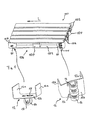
- the pallet 100 shown in FIG. 1 comprises two rows of boards 102, which are spaced apart from one another by spacer blocks 104, in order to enable transport by means of a forklift or a pallet truck.
- Pallet 100 is a so-called Euro pallet and is made of wood. With the transport device according to the invention, it is also possible to transport differently designed pallets, which may consist of other materials.
- roller units 10 are arranged on the respective spacing blocks 104 which are most distant from one another.
- each roller unit has a U-shaped clamping bracket 12 for clamping on the respective spacer block 104 of the pallet 100.
- the clamping bracket comprises two side legs 12a, which are connected to one another by a connecting leg (base plate) 12b.
- the two side legs 12a of the clamping bracket 12 can be inclined somewhat inwards in order to be clamped onto the respective spacer block 104 of the pallet to be able to make; they enclose the pallet after the roller unit 10 is clamped onto the pallet.
- At least one of the side legs 12a can have a handle 122, as shown in FIG. 14, which is designed in particular as an opening (passage) in the side leg 12a.
- the handle 122 enables both the simple transport of the clamping bracket 12 and the simple clamping of the clamping bracket 12 to the pallet 100 and the simple detachment of the clamping bracket 12 from the pallet 100. Furthermore, the handle 122 enables the clamping bracket 12 to be easily attached to a wall to keep it ready for the next use.
- At least one of the side legs 12a on its side facing away from the rolling element 16 can have an outwardly angled edge (insertion edge) 121, which facilitates the clamping of the clamping bracket or the insertion of the pallet into the clamping bracket.
- This outwardly angled edge 121 connects to the inwardly inclined part of the side leg 12a.
- the clamping bracket 12 is rigid and has resilient intermediate pieces, e.g. Leaf springs or rubber strips that clamp with the respective spacer block 104 of the pallet 100.
- Each rolling unit 10 also has a holder 14 which rotatably supports at least one rolling element, in particular a wheel 16, on an axis 18.
- the material of the clamping bracket 12 is preferably plastic or sheet metal.
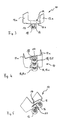
- FIG. 1 and 3 show an embodiment of a roller unit 10 in which the holder 14 rotatably supports a wheel 16 which points in the direction of a longitudinal axis L of the pallet 100. It is therefore arranged in a plane which is arranged parallel to the top and bottom of the pallet 100,
- FIG. 1 and 4 show an embodiment of a roller unit 10 in which the holder 14 rotatably supports three wheels 16 and 16I, 16c, 16r, respectively.
- the three wheels are arranged essentially next to each other; however, they can be staggered.
- the middle wheel 16c of the three wheels points in the direction of the longitudinal axis L of the pallet 100, that is to say it is arranged in a plane which is arranged parallel to the top and bottom of the pallet 100, while the two outer wheels 16l and 16r are in a predeterminable manner Angles are arranged facing outwards, this angle preferably being between 10 ° and 20 °, in particular 15 °. However, the invention is not restricted to this angular range or angular value.
- the middle wheel 16c of the three wheels 16c, 16l, 16r preferably has a larger diameter than the two outer wheels 16l, 16r.
- the holder 14 can have three axes for supporting the three wheels 16 or have a common axis 18 for supporting the three wheels 16.
- the middle wheel 16c of the three wheels 16 is mounted at a greater distance from the clamping bracket 12 than the two outer wheels 16l, 16r.
- the two side legs 12a are formed with a different width, so that when the clamping bracket 12 is placed on a spacer block 104 of the pallet 100, the direction is predetermined, since only the narrower side legs 12a face the inner side of the pallet 100 can be introduced pointing.
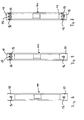
- FIGS. 2A to 2C show the pallet 100 equipped with two roller units 10 in FIG. 1, which is in a substantially vertical position, FIG. 2A showing the vertical position in the straight direction of the pallet 100, FIG. 2B the position inclined slightly to the left Pallet 100 and Figure 2C shows the position of the pallet 100 inclined slightly to the right in order to make a right turn. It can be seen from FIGS. 2A to 2C how the transport direction can be influenced by simply tilting the pallet 1.
- the roller unit 10 has a holder 14 with two wheels 16 (double wheel), the holder 14 being provided with a swivel mechanism 20, as is e.g. is known from WO 92/155377 for controlling the direction of travel of a skateboard.
- both wheels 16 are rotatably arranged on a common axis 18.
- the radius of the cornering of the pallet 100 is determined by the inclination angle of the pallet 100 in the vertical direction, so that the cornering can be controlled in a targeted manner.
- two wheels 16 can also be designed as double wheels without the swivel mechanism 20, so that the double wheel cannot be steered or not steered.
- FIGS. 6 to 11 schematically show different combinations of roller units 10 which are arranged on the pallet 100.
- FIG. 6 shows a pallet 100 with two similarly designed roller units 10, each of which has a wheel 16.
- the pallet 100 is not steerable during transportation.
- FIG. 7 shows a pallet 100 with two roller units 10, one roller unit 10 having three wheels 16 and the other roller unit 10 having a wheel 16.
- the pallet 100 is steerable during transportation.
- FIG. 8 shows a pallet 100 with similarly designed roller units 10, each of which has three wheels.
- the pallet 100 is steerable in such a way that the pallet 100 can be steered by its inclination, the pallet 100 reacting in a counter-steering manner, i.e. both sides swivel in different directions, so that tight cornering is possible.
- FIG. 9 shows a pallet 100 with two similarly designed roller units 10, each of which has two wheels 16 (double wheel).
- the pallet 100 is comparatively stable in the vertical position, this pallet not being steerable during transport.
- FIG. 10 shows a pallet 100 with two roller units 10, of which one roller unit 10 has a wheel 16 and the other roller unit 10 is designed with two wheels 16 (double wheel) with a swivel mechanism 20.
- the radius of travel of the pallet 100 can be controlled by the degree of inclination of the pallet 100.
- FIG. 11 shows a pallet 100 with two similarly designed roller units 10, each of which has two wheels 16 (double wheel) with a swivel mechanism 20.
- the radius of the transport travel of the pallet 100 can be controlled by the degree of the inclination of the pallet 100, very tight cornering being possible in this embodiment.
- clamping brackets are pivotally connected to the pallet 100 such that they can be pivoted into the interior of the pallet 100, which is formed by the spacer blocks 104.
- FIG. 12 shows a perspective view and a side view of a pallet 100, on which only one roller unit 10 is provided on the middle spacer 104 of the pallet 100.
- the roller unit 10 has two wheels.
- FIG. 13 shows the pallet 100 in various working steps when erecting from the horizontal position, via an inclined position into the vertical position. Furthermore, FIG. 13 shows a side view of the pallet with the transport device in a vertical position.
- FIG. 14 shows a preferred embodiment of the roller unit 10.
- This comprises a connecting leg (base plate) 12b, two side legs 12a, and wheels 16l, 16c and 16r held by a holder 14.
- both side legs 12a have an outwardly angled edge 121 on their side facing away from the wheels.
- the two side legs 12a of the clamping bracket 12 are slightly inclined inward in order to facilitate clamping onto the respective spacer block 104 of the pallet.
- One of the side legs 12a has a handle 122 which is designed as an opening in the side leg 12a.
- both side legs 12a have on their side facing away from the wheels 16 an outwardly angled edge (insertion edge) 121 which adjoins the part of the side leg 12a which is inclined inward.
- the transport device according to the invention can also be implemented in embodiments which are mixed forms of the above-described embodiments.
- it can have one, two or three roller units, and the roller units can be configured in the same way or in different ways with regard to their rolling elements or wheels.
- the invention also relates to a rolling unit 10 and a pallet 100 with a transport device described above.
Landscapes
- Engineering & Computer Science (AREA)
- Mechanical Engineering (AREA)
- Chemical & Material Sciences (AREA)
- Combustion & Propulsion (AREA)
- Transportation (AREA)
- Handcart (AREA)
Applications Claiming Priority (2)
| Application Number | Priority Date | Filing Date | Title |
|---|---|---|---|
| DE10328065 | 2003-06-23 | ||
| DE2003128065 DE10328065A1 (de) | 2003-06-23 | 2003-06-23 | Transportvorrichtung für eine Palette |
Publications (1)
| Publication Number | Publication Date |
|---|---|
| EP1491455A1 true EP1491455A1 (fr) | 2004-12-29 |
Family
ID=33039341
Family Applications (1)
| Application Number | Title | Priority Date | Filing Date |
|---|---|---|---|
| EP04011819A Withdrawn EP1491455A1 (fr) | 2003-06-23 | 2004-05-18 | Dispositif de transport pour une pallette |
Country Status (2)
| Country | Link |
|---|---|
| EP (1) | EP1491455A1 (fr) |
| DE (2) | DE10328065A1 (fr) |
Families Citing this family (3)
| Publication number | Priority date | Publication date | Assignee | Title |
|---|---|---|---|---|
| NL1038212C2 (nl) * | 2010-08-31 | 2012-03-01 | W J Schuurmans Cromvoirt B V | Pallettransportgereedschap. |
| DE102010063461A1 (de) * | 2010-12-17 | 2012-06-21 | Heinz Buse | Logistiksystem und Plattform |
| DE202011050527U1 (de) * | 2011-06-22 | 2012-09-24 | Norbert Heimann | Manuell bewegbares Transport- und/oder Lagermittel |
Citations (10)
| Publication number | Priority date | Publication date | Assignee | Title |
|---|---|---|---|---|
| DD41330A (fr) | ||||
| DE1788388U (de) | 1959-01-09 | 1959-05-06 | Holzwerke Zapfendorf G M B H | Fahrbare palette. |
| US2916771A (en) | 1955-11-16 | 1959-12-15 | Lang Kurt | Pressing tools particularly for the manufacture of large-area pressings |
| GB925081A (en) * | 1958-10-06 | 1963-05-01 | John Logan Andrew | Improvements in and relating to furniture and like castors |
| DE3414288C2 (fr) | 1984-04-14 | 1987-09-10 | Philips Patentverwaltung Gmbh, 2000 Hamburg, De | |
| DE9104280U1 (de) | 1991-04-09 | 1992-08-06 | Stork GmbH & Co. KG, 4834 Marienfeld | Transport- und Montagegerät für Türen, Tore oder Fenster |
| WO1992015537A1 (fr) | 1991-03-07 | 1992-09-17 | Shinagawa Rozai Kabushiki Kaisha | Boue pour orifice de sous-tirage de haut-fourneau |
| DE29823445U1 (de) | 1997-02-27 | 1999-05-27 | Ameisbichler, Rudolf, Wilhelmsburg | Rolle zur Anbringung an einer Palette |
| DE19855595A1 (de) | 1998-12-02 | 2000-06-15 | Bauelemente Gmbh | Aufsteckfuß für Paletten |
| CH691178A5 (de) | 2000-02-28 | 2001-05-15 | Hanspeter Suter | Profilplatte für Palett-Roller bei Europalette. |
Family Cites Families (1)
| Publication number | Priority date | Publication date | Assignee | Title |
|---|---|---|---|---|
| US2816771A (en) * | 1955-11-25 | 1957-12-17 | Elmer R Hunt | Moving dolly for tables and the like |
-
2003
- 2003-06-23 DE DE2003128065 patent/DE10328065A1/de not_active Withdrawn
-
2004
- 2004-05-18 DE DE202004008013U patent/DE202004008013U1/de not_active Expired - Lifetime
- 2004-05-18 EP EP04011819A patent/EP1491455A1/fr not_active Withdrawn
Patent Citations (10)
| Publication number | Priority date | Publication date | Assignee | Title |
|---|---|---|---|---|
| DD41330A (fr) | ||||
| US2916771A (en) | 1955-11-16 | 1959-12-15 | Lang Kurt | Pressing tools particularly for the manufacture of large-area pressings |
| GB925081A (en) * | 1958-10-06 | 1963-05-01 | John Logan Andrew | Improvements in and relating to furniture and like castors |
| DE1788388U (de) | 1959-01-09 | 1959-05-06 | Holzwerke Zapfendorf G M B H | Fahrbare palette. |
| DE3414288C2 (fr) | 1984-04-14 | 1987-09-10 | Philips Patentverwaltung Gmbh, 2000 Hamburg, De | |
| WO1992015537A1 (fr) | 1991-03-07 | 1992-09-17 | Shinagawa Rozai Kabushiki Kaisha | Boue pour orifice de sous-tirage de haut-fourneau |
| DE9104280U1 (de) | 1991-04-09 | 1992-08-06 | Stork GmbH & Co. KG, 4834 Marienfeld | Transport- und Montagegerät für Türen, Tore oder Fenster |
| DE29823445U1 (de) | 1997-02-27 | 1999-05-27 | Ameisbichler, Rudolf, Wilhelmsburg | Rolle zur Anbringung an einer Palette |
| DE19855595A1 (de) | 1998-12-02 | 2000-06-15 | Bauelemente Gmbh | Aufsteckfuß für Paletten |
| CH691178A5 (de) | 2000-02-28 | 2001-05-15 | Hanspeter Suter | Profilplatte für Palett-Roller bei Europalette. |
Also Published As
| Publication number | Publication date |
|---|---|
| DE10328065A1 (de) | 2005-01-13 |
| DE202004008013U1 (de) | 2004-09-23 |
Similar Documents
| Publication | Publication Date | Title |
|---|---|---|
| DE102010017709A1 (de) | Transportwagen | |
| EP2431253B1 (fr) | Structure de transport modulaire | |
| EP2505453B1 (fr) | chariot de transport | |
| EP1491455A1 (fr) | Dispositif de transport pour une pallette | |
| EP1526058A1 (fr) | Chariot de transport | |
| DE10062425A1 (de) | Etagen-Transportwagen | |
| EP1820714A2 (fr) | Chariot de transport | |
| WO2009146836A1 (fr) | Dispositif de transport | |
| DE102011122222B4 (de) | Transportwagen | |
| DE29617184U1 (de) | Palette und Schleppgerät hierfür | |
| DE102007052914A1 (de) | Wagen, insbesondere Handwagen | |
| DE202004013844U1 (de) | Transportvorrichtung für eine Palette | |
| EP1084930A2 (fr) | Chariot de transport emboítable pour le transport de plateaux posés verticalement | |
| DE8903451U1 (de) | Mit entsprechenden Wagen schachtelbarer Schubgepäckwagen | |
| EP1285856A2 (fr) | Dispositif pour le stockage et le transport de dalles | |
| DE3117512C2 (de) | Werktisch | |
| DE7917706U1 (de) | Transportwagen | |
| EP1472130B1 (fr) | Chariot pour magasins emboitable | |
| DE202006007373U1 (de) | Rollwagen | |
| DE19621012A1 (de) | Transportwagen für Plattenmaterial | |
| DE29609369U1 (de) | Werkstatt-Transportwagen für Kraftfahrzeuge | |
| CH720910A2 (de) | Gerüst für Wechselbrücken | |
| DE8815152U1 (de) | Mit entsprechenden Wagen schachtelbarer Schubgepäckwagen | |
| DE3144929C2 (fr) | ||
| DE29505920U1 (de) | Handkarren für Schwerlasten |
Legal Events
| Date | Code | Title | Description |
|---|---|---|---|
| PUAI | Public reference made under article 153(3) epc to a published international application that has entered the european phase |
Free format text: ORIGINAL CODE: 0009012 |
|
| AK | Designated contracting states |
Kind code of ref document: A1 Designated state(s): AT BE BG CH CY CZ DE DK EE ES FI FR GB GR HU IE IT LI LU MC NL PL PT RO SE SI SK TR |
|
| AX | Request for extension of the european patent |
Extension state: AL HR LT LV MK |
|
| 17P | Request for examination filed |
Effective date: 20050629 |
|
| AKX | Designation fees paid |
Designated state(s): AT BE BG CH CY CZ DE DK EE ES FI FR GB GR HU IE IT LI LU MC NL PL PT RO SE SI SK TR |
|
| 17Q | First examination report despatched |
Effective date: 20090129 |
|
| GRAP | Despatch of communication of intention to grant a patent |
Free format text: ORIGINAL CODE: EPIDOSNIGR1 |
|
| GRAC | Information related to communication of intention to grant a patent modified |
Free format text: ORIGINAL CODE: EPIDOSCIGR1 |
|
| STAA | Information on the status of an ep patent application or granted ep patent |
Free format text: STATUS: THE APPLICATION IS DEEMED TO BE WITHDRAWN |
|
| 18D | Application deemed to be withdrawn |
Effective date: 20101201 |