EP1491480A1 - Devidoir pour tuyau d'air - Google Patents
Devidoir pour tuyau d'air Download PDFInfo
- Publication number
- EP1491480A1 EP1491480A1 EP20040253784 EP04253784A EP1491480A1 EP 1491480 A1 EP1491480 A1 EP 1491480A1 EP 20040253784 EP20040253784 EP 20040253784 EP 04253784 A EP04253784 A EP 04253784A EP 1491480 A1 EP1491480 A1 EP 1491480A1
- Authority
- EP
- European Patent Office
- Prior art keywords
- reel
- nozzle
- housing
- hose
- pulley
- Prior art date
- Legal status (The legal status is an assumption and is not a legal conclusion. Google has not performed a legal analysis and makes no representation as to the accuracy of the status listed.)
- Withdrawn
Links
- 239000012530 fluid Substances 0.000 claims abstract description 14
- 238000004891 communication Methods 0.000 claims abstract description 13
- 230000000717 retained effect Effects 0.000 claims abstract description 7
- 238000004804 winding Methods 0.000 claims description 12
- 238000007789 sealing Methods 0.000 claims description 7
- 238000010276 construction Methods 0.000 description 1
- 230000008878 coupling Effects 0.000 description 1
- 238000010168 coupling process Methods 0.000 description 1
- 238000005859 coupling reaction Methods 0.000 description 1
- 230000007246 mechanism Effects 0.000 description 1
- 239000003973 paint Substances 0.000 description 1
- 230000001681 protective effect Effects 0.000 description 1
- 230000008439 repair process Effects 0.000 description 1
Images

Classifications
-
- B—PERFORMING OPERATIONS; TRANSPORTING
- B65—CONVEYING; PACKING; STORING; HANDLING THIN OR FILAMENTARY MATERIAL
- B65H—HANDLING THIN OR FILAMENTARY MATERIAL, e.g. SHEETS, WEBS, CABLES
- B65H75/00—Storing webs, tapes, or filamentary material, e.g. on reels
- B65H75/02—Cores, formers, supports, or holders for coiled, wound, or folded material, e.g. reels, spindles, bobbins, cop tubes, cans, mandrels or chucks
- B65H75/34—Cores, formers, supports, or holders for coiled, wound, or folded material, e.g. reels, spindles, bobbins, cop tubes, cans, mandrels or chucks specially adapted or mounted for storing and repeatedly paying-out and re-storing lengths of material provided for particular purposes, e.g. anchored hoses, power cables
- B65H75/38—Cores, formers, supports, or holders for coiled, wound, or folded material, e.g. reels, spindles, bobbins, cop tubes, cans, mandrels or chucks specially adapted or mounted for storing and repeatedly paying-out and re-storing lengths of material provided for particular purposes, e.g. anchored hoses, power cables involving the use of a core or former internal to, and supporting, a stored package of material
- B65H75/44—Constructional details
- B65H75/4457—Arrangements of the frame or housing
- B65H75/446—Arrangements of the frame or housing for releasably or permanently attaching the frame to a wall, on a floor or on a post or the like
- B65H75/4463—Swivelling attachment
-
- B—PERFORMING OPERATIONS; TRANSPORTING
- B65—CONVEYING; PACKING; STORING; HANDLING THIN OR FILAMENTARY MATERIAL
- B65H—HANDLING THIN OR FILAMENTARY MATERIAL, e.g. SHEETS, WEBS, CABLES
- B65H75/00—Storing webs, tapes, or filamentary material, e.g. on reels
- B65H75/02—Cores, formers, supports, or holders for coiled, wound, or folded material, e.g. reels, spindles, bobbins, cop tubes, cans, mandrels or chucks
- B65H75/34—Cores, formers, supports, or holders for coiled, wound, or folded material, e.g. reels, spindles, bobbins, cop tubes, cans, mandrels or chucks specially adapted or mounted for storing and repeatedly paying-out and re-storing lengths of material provided for particular purposes, e.g. anchored hoses, power cables
- B65H75/38—Cores, formers, supports, or holders for coiled, wound, or folded material, e.g. reels, spindles, bobbins, cop tubes, cans, mandrels or chucks specially adapted or mounted for storing and repeatedly paying-out and re-storing lengths of material provided for particular purposes, e.g. anchored hoses, power cables involving the use of a core or former internal to, and supporting, a stored package of material
-
- B—PERFORMING OPERATIONS; TRANSPORTING
- B65—CONVEYING; PACKING; STORING; HANDLING THIN OR FILAMENTARY MATERIAL
- B65H—HANDLING THIN OR FILAMENTARY MATERIAL, e.g. SHEETS, WEBS, CABLES
- B65H75/00—Storing webs, tapes, or filamentary material, e.g. on reels
- B65H75/02—Cores, formers, supports, or holders for coiled, wound, or folded material, e.g. reels, spindles, bobbins, cop tubes, cans, mandrels or chucks
- B65H75/34—Cores, formers, supports, or holders for coiled, wound, or folded material, e.g. reels, spindles, bobbins, cop tubes, cans, mandrels or chucks specially adapted or mounted for storing and repeatedly paying-out and re-storing lengths of material provided for particular purposes, e.g. anchored hoses, power cables
- B65H75/38—Cores, formers, supports, or holders for coiled, wound, or folded material, e.g. reels, spindles, bobbins, cop tubes, cans, mandrels or chucks specially adapted or mounted for storing and repeatedly paying-out and re-storing lengths of material provided for particular purposes, e.g. anchored hoses, power cables involving the use of a core or former internal to, and supporting, a stored package of material
- B65H75/40—Cores, formers, supports, or holders for coiled, wound, or folded material, e.g. reels, spindles, bobbins, cop tubes, cans, mandrels or chucks specially adapted or mounted for storing and repeatedly paying-out and re-storing lengths of material provided for particular purposes, e.g. anchored hoses, power cables involving the use of a core or former internal to, and supporting, a stored package of material mobile or transportable
-
- B—PERFORMING OPERATIONS; TRANSPORTING
- B65—CONVEYING; PACKING; STORING; HANDLING THIN OR FILAMENTARY MATERIAL
- B65H—HANDLING THIN OR FILAMENTARY MATERIAL, e.g. SHEETS, WEBS, CABLES
- B65H75/00—Storing webs, tapes, or filamentary material, e.g. on reels
- B65H75/02—Cores, formers, supports, or holders for coiled, wound, or folded material, e.g. reels, spindles, bobbins, cop tubes, cans, mandrels or chucks
- B65H75/34—Cores, formers, supports, or holders for coiled, wound, or folded material, e.g. reels, spindles, bobbins, cop tubes, cans, mandrels or chucks specially adapted or mounted for storing and repeatedly paying-out and re-storing lengths of material provided for particular purposes, e.g. anchored hoses, power cables
- B65H75/38—Cores, formers, supports, or holders for coiled, wound, or folded material, e.g. reels, spindles, bobbins, cop tubes, cans, mandrels or chucks specially adapted or mounted for storing and repeatedly paying-out and re-storing lengths of material provided for particular purposes, e.g. anchored hoses, power cables involving the use of a core or former internal to, and supporting, a stored package of material
- B65H75/44—Constructional details
- B65H75/4457—Arrangements of the frame or housing
- B65H75/4471—Housing enclosing the reel
-
- B—PERFORMING OPERATIONS; TRANSPORTING
- B65—CONVEYING; PACKING; STORING; HANDLING THIN OR FILAMENTARY MATERIAL
- B65H—HANDLING THIN OR FILAMENTARY MATERIAL, e.g. SHEETS, WEBS, CABLES
- B65H75/00—Storing webs, tapes, or filamentary material, e.g. on reels
- B65H75/02—Cores, formers, supports, or holders for coiled, wound, or folded material, e.g. reels, spindles, bobbins, cop tubes, cans, mandrels or chucks
- B65H75/34—Cores, formers, supports, or holders for coiled, wound, or folded material, e.g. reels, spindles, bobbins, cop tubes, cans, mandrels or chucks specially adapted or mounted for storing and repeatedly paying-out and re-storing lengths of material provided for particular purposes, e.g. anchored hoses, power cables
- B65H75/38—Cores, formers, supports, or holders for coiled, wound, or folded material, e.g. reels, spindles, bobbins, cop tubes, cans, mandrels or chucks specially adapted or mounted for storing and repeatedly paying-out and re-storing lengths of material provided for particular purposes, e.g. anchored hoses, power cables involving the use of a core or former internal to, and supporting, a stored package of material
- B65H75/44—Constructional details
- B65H75/48—Automatic re-storing devices
-
- B—PERFORMING OPERATIONS; TRANSPORTING
- B65—CONVEYING; PACKING; STORING; HANDLING THIN OR FILAMENTARY MATERIAL
- B65H—HANDLING THIN OR FILAMENTARY MATERIAL, e.g. SHEETS, WEBS, CABLES
- B65H2701/00—Handled material; Storage means
- B65H2701/30—Handled filamentary material
- B65H2701/33—Hollow or hose-like material
-
- Y—GENERAL TAGGING OF NEW TECHNOLOGICAL DEVELOPMENTS; GENERAL TAGGING OF CROSS-SECTIONAL TECHNOLOGIES SPANNING OVER SEVERAL SECTIONS OF THE IPC; TECHNICAL SUBJECTS COVERED BY FORMER USPC CROSS-REFERENCE ART COLLECTIONS [XRACs] AND DIGESTS
- Y10—TECHNICAL SUBJECTS COVERED BY FORMER USPC
- Y10T—TECHNICAL SUBJECTS COVERED BY FORMER US CLASSIFICATION
- Y10T137/00—Fluid handling
- Y10T137/0318—Processes
- Y10T137/0402—Cleaning, repairing, or assembling
- Y10T137/0491—Valve or valve element assembling, disassembling, or replacing
-
- Y—GENERAL TAGGING OF NEW TECHNOLOGICAL DEVELOPMENTS; GENERAL TAGGING OF CROSS-SECTIONAL TECHNOLOGIES SPANNING OVER SEVERAL SECTIONS OF THE IPC; TECHNICAL SUBJECTS COVERED BY FORMER USPC CROSS-REFERENCE ART COLLECTIONS [XRACs] AND DIGESTS
- Y10—TECHNICAL SUBJECTS COVERED BY FORMER USPC
- Y10T—TECHNICAL SUBJECTS COVERED BY FORMER US CLASSIFICATION
- Y10T137/00—Fluid handling
- Y10T137/6851—With casing, support, protector or static constructional installations
- Y10T137/6918—With hose storage or retrieval means
- Y10T137/6932—With retrieval means
- Y10T137/6943—Biased to retracted position
-
- Y—GENERAL TAGGING OF NEW TECHNOLOGICAL DEVELOPMENTS; GENERAL TAGGING OF CROSS-SECTIONAL TECHNOLOGIES SPANNING OVER SEVERAL SECTIONS OF THE IPC; TECHNICAL SUBJECTS COVERED BY FORMER USPC CROSS-REFERENCE ART COLLECTIONS [XRACs] AND DIGESTS
- Y10—TECHNICAL SUBJECTS COVERED BY FORMER USPC
- Y10T—TECHNICAL SUBJECTS COVERED BY FORMER US CLASSIFICATION
- Y10T137/00—Fluid handling
- Y10T137/8158—With indicator, register, recorder, alarm or inspection means
- Y10T137/8225—Position or extent of motion indicator
- Y10T137/8242—Electrical
-
- Y—GENERAL TAGGING OF NEW TECHNOLOGICAL DEVELOPMENTS; GENERAL TAGGING OF CROSS-SECTIONAL TECHNOLOGIES SPANNING OVER SEVERAL SECTIONS OF THE IPC; TECHNICAL SUBJECTS COVERED BY FORMER USPC CROSS-REFERENCE ART COLLECTIONS [XRACs] AND DIGESTS
- Y10—TECHNICAL SUBJECTS COVERED BY FORMER USPC
- Y10T—TECHNICAL SUBJECTS COVERED BY FORMER US CLASSIFICATION
- Y10T137/00—Fluid handling
- Y10T137/8158—With indicator, register, recorder, alarm or inspection means
- Y10T137/8326—Fluid pressure responsive indicator, recorder or alarm
-
- Y—GENERAL TAGGING OF NEW TECHNOLOGICAL DEVELOPMENTS; GENERAL TAGGING OF CROSS-SECTIONAL TECHNOLOGIES SPANNING OVER SEVERAL SECTIONS OF THE IPC; TECHNICAL SUBJECTS COVERED BY FORMER USPC CROSS-REFERENCE ART COLLECTIONS [XRACs] AND DIGESTS
- Y10—TECHNICAL SUBJECTS COVERED BY FORMER USPC
- Y10T—TECHNICAL SUBJECTS COVERED BY FORMER US CLASSIFICATION
- Y10T137/00—Fluid handling
- Y10T137/8593—Systems
- Y10T137/877—With flow control means for branched passages
- Y10T137/87885—Sectional block structure
Definitions
- the present invention relates generally to air hose reels and, in particular, to a reel for storing and deploying an air hose to be connected between a source of pressured air and a pneumatic tool which reel can be mounted for use in a specific location and easily detached from its mounting bracket and used remotely.
- Air hoses are well known and are typically utilized to connect a source of pressured air to various pneumatically powered tools such as paint atomizers, cutters, grinders, drills, screwdrivers, hammers, rivet guns, impact wrenches, ratchets, sanders and polishers, among others.
- pneumatically powered tools such as paint atomizers, cutters, grinders, drills, screwdrivers, hammers, rivet guns, impact wrenches, ratchets, sanders and polishers, among others.
- Take-up reels for managing the use and storage of air hoses and electrical cords are well known.
- Such reels consist basically of a spool rotatably affixed to a structural component whereby the spool is manually or automatically rotated to wind an elongated hose or cord thereabout.
- Such automatic reels employ a variety of spring and ratchet mechanisms for maintaining the hose/cord in the extended position and rewinding the hose/cord onto the spool when it is no longer needed.
- Such reels are particularly useful in industrial or commercial settings such as automobile repair shops, machine shops, carpentry shops and construction sites. These reels permit workers to readily access pressurized air as needed for the operation of portable pneumatic tools at various locations remote from an existing air compressor.
- the use of air hose reels makes it possible to provide only a short air fitting, such as a coupling or the like, on the various pneumatic tools thereby simplifying the movement and storage of the disconnected pneumatic tools.
- retracting reels for electric cords and air hoses basically include a spool mounted on a shaft supported for rotation on a bracket or housing, and a cooperating ratchet and pawl to arrest the rotation of the spool when the air hose or electric cord has been paid out to a desired length, and a spring for rotating the spool in a direction to rewind the air hose or electric cord when the ratchet and pawl are disengaged.
- Such electrical cord reels are shown, for example, in the United States Patent Numbers: 3,619,518; 3,715,526; 3,808,382; 4,726,538; and 6,273,354.
- the present invention concerns an air hose reel for storing an air hose and connecting the air hose with a pressurized air supply.
- the air hose reel includes a hollow reel housing having first and second cup-shaped housing halves, each of the housing halves having a generally inverted U-shaped handle portion extending outwardly therefrom, the handle portions cooperating to form a handle for hand carrying the air hose reel.
- a generally U-shaped mounting bracket for attaching the air hose reel to a mounting surface is attached by a rod extending through apertures formed in the mounting bracket and apertures formed in at least one of the handle portions, the rod detachably attaching the housing to the mounting bracket.
- a nut releasably attaches to the rod and prevents removal of the rod from the mounting bracket apertures and the at least one handle portion apertures.
- a flange is mounted on an exterior of the second half of the housing, the flange including a first tubular portion extending outwardly from the reel housing and adapted to be connected to a source of pressured air, and a second tubular portion extending inside the reel housing and in fluid communication with the first tubular portion, the second tubular portion having an annular groove formed in an exterior surface and an O-ring retained in the groove.
- a pulley is rotatably mounted inside the reel housing on an axis of rotation.
- a nozzle is mounted on the pulley, the nozzle having a tubular nozzle inlet receiving the second tubular portion, the O-ring sealing between the exterior surface of the second tubular portion and an interior surface of the nozzle inlet, the nozzle having a nozzle outlet in fluid communication with the nozzle inlet, the nozzle outlet extending transverse to the axis of rotation.
- a reel hose is wound on the pulley, the reel hose having one end attached to the nozzle outlet by a hose clamp and an opposite end extending through the housing aperture.
- a shaft is mounted in the first half of the reel housing, the shaft rotatably supporting the pulley.
- a return spring is mounted in the pulley for automatically winding up the reel hose, the return spring having one end attached to the pulley and an opposite end attached to the shaft.
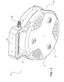
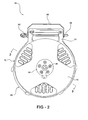
- the air hose reel 10 includes a hollow reel housing 12 formed from a pair of cup-shaped halves, a first or left half 14 and a second or right half 16 .
- the housing 12 includes an inverted U-shaped handle formed from a first or left handle portion 13 extending from a top surface of the housing first half 14 and a second or right handle portion 15 extending from a top surface of the housing second half 16 .
- an inner surface of the housing first half 14 has a plurality of detent members 18 formed thereon and a mounting boss 20 extending upwardly from a center portion thereof.
- the housing second half 16 defines a recess 22 that receives a flange 24 .
- the flange 24 is attached to the outer surface of the housing second half 16 by a plurality of fasteners 25 (Fig. 2).
- the flange 24 includes a first tubular portion 26 extending outwardly therefrom and a second tubular portion 28 extending inwardly therefrom.
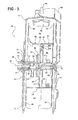
- the tubular portions 26 and 28 are coaxial and define an axis of rotation 29 (Fig. 3) discussed below.
- the first tubular portion 26 threadably connects to a threaded end of an air supply hose 31 .
- the air supply hose 31 is approximately three feet long and preferably is connected to a compressed air supply (not shown) such as an outlet of an air compressor, a compressed air receiver or the like.
- the first tubular portion 26 of the flange 24 therefore, functions as an external air inlet for the air hose reel 10 .
- An air hose nozzle 30 includes a tubular nozzle inlet 32 that receives the second tubular portion 28 that extends through a central aperture in the outer surface of the housing second half 16 .
- a tubular nozzle outlet 34 extends radially from an outer surface of the inlet 32 and is in fluid communication with the interior of the inlet.
- the second tubular portion 28 includes an annular groove 36 (Fig. 3) formed in the outer surface thereof for receiving and retaining an O-ring 38.
- the O-ring 38 provides a rotating air seal between the outer surface of the second tubular portion 28 and the inner surface of the nozzle inlet 32 .
- a snap ring 40 is received in an annular groove 41 formed in the outer surface of a free end of the inlet 32 and the snap ring is trapped between the flange 24 and the housing second half 16 to secure the nozzle 30 to the housing 12 .
- the nozzle outlet 34 functions as an outlet for the pressured air provided to the hose reel 10 through the air supply hose 31 .
- the air hose nozzle 30 also includes a radially extending flange 42 formed at an end of the nozzle inlet 32 opposite the groove 41 .
- the flange 42 is attached to a mounting boss 44 extending axially outwardly from an internal surface of a generally disk-shaped first pulley half 46 .
- the flange 42 is attached to the mounting boss 44 by a plurality of fasteners (not shown).
- the first pulley half 46 includes a plurality of radially extending flanges 48 evenly spaced about a periphery of an outer edge of a first winding drum half 49 .
- the winding drum 49 outer wall has an aperture 50 formed therein extending from an inner edge to permit access to the nozzle outlet 34 .
- a second pulley half 52 has a second winding drum half 53 with a plurality of radially extending flanges 54 evenly spaced about a periphery of an outer edge of the second drum half.
- the first pulley half 46 and the second pulley half 52 when attached at the inner edges as shown in Fig. 3, form a pulley, indicated generally at 56 .
- a radially extending wall 57 of the second pulley half 52 includes a plurality of axially outwardly extending female bosses 58a that mate with corresponding axially outwardly extending male bosses 58b (Fig. 3) on a facing radially extending wall 59 of the first pulley half 46 .
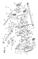
- a tab 60 (Fig. 4) extends axially from the inner edge of the second winding drum half 53 to partially close the aperture 50 .
- the inner edges of the drum halves 49 and 53 interlock, as shown in Fig. 3, which assists in the attachment of the first pulley half 46 and the second pulley half 52 .
- a cover plate 62 is attached to the outer edge of the second winding drum half 53 opposite the wall 57 .
- the cover plate 62 and the wall 57 define a cavity 64 (Fig. 3) therebetween.
- a pawl member 63 is rotatably mounted on a boss (not shown) or similar mounting location formed on an outer surface of the end plate 62 .
- An end of the pawl member 63 is attached to one end of a tension spring 65 .
- the other end of the tension spring member is attached to the outer surface of the end plate 62 .
- the pawl member 63 cooperates with the plurality of detent members 18 during rotation of the pulley 56 and the end plate 62 .
- a generally cylindrical shaft 66 extends through a coiled return spring 67 that is retained in the cavity 64 .
- the shaft 66 includes a reduced diameter first end 68 with a pair of opposed flats 70 formed thereon and an opposed reduced diameter second end 72 .
- the first end 68 of the shaft member 66 fits into the mounting boss 20 of the housing first half 14 with the flats 70 cooperating with a correspondingly shaped central aperture of the mounting boss 20 for preventing rotation of the shaft member 66 with respect to the first half 14.
- An inner end of the return spring 67 is attached to the larger diameter central portion of the shaft 66 .
- An outer end of the spring 67 is attached to the second winding drum half 52 .
- a reel hose 74 is attached at a first end 73 thereof to the nozzle outlet 34 by a hose clamp 76 .
- the reel hose 74 extends from the nozzle outlet 34 through the aperture 50 and into a space 78 between the flanges 48 and 54 .
- a second end 75 of the reel hose 74 extends through an aperture 80 formed in the housing first and second halves 14 and 16 respectively.
- the reel hose 74 is approximately twenty-five feet long and the second end 75 is adapted to be attached to a pneumatic tool (not shown) or the like.
- the reel hose 74 includes a ball stop 82 attached thereto with a split insert 84 to aid in retaining the ball stop 82 on the hose 74 .
- the ball stop 82 and insert 84 are attached to a portion of the reel hose 74 external to the reel case 12 near the end 75 .
- the ball stop 82 has an exterior diameter larger than the aperture 80 .
- the ball stop 82 is operable to stop the accidental retraction of the second end 75 of the air hose 74 into the space 78 during operation of the air hose reel 10 , outlined in more detail below.
- a generally U-shaped mounting bracket 86 has a pair of apertures 87 formed in opposed legs that are spaced to fit over the first and second handle portions 13 and 15 .
- a rod 88 extends through the apertures 87 and a pair of corresponding apertures 89 formed in the second handle portion 15 to releasably attach the mounting bracket 86 to the reel housing 12 .
- the rod 88 can be retained by a nut 90 , or similar fastening device.
- the air hose reel 10 is easy to assemble.
- the spring 67 , the shaft 66 , the pawl 63 , the end plate 62 , the pulley 56 , and the nozzle 30 are assembled as a pulley subassembly.
- the hose 74 is attached to the nozzle outlet 34 of the nozzle 30 by the hose clamp 76 , with the end 75 of the hose 74 extending through the aperture 50 .
- the first end 68 of the shaft member 66 is then mounted in the mounting boss 20.
- the flange 24 is attached to the second half 16 of the reel housing 12 and the first half 14 and the second half 16 are joined with the end 75 of the hose extending through the aperture 80 .
- the air supply hose 31 is then attached to the first tubular portion 26 to complete the air hose reel 10 .
- the first half 14 and the second half 16 are preferably attached at respective circumferential surfaces thereof by a plurality of fasteners (not shown).
- the assembled air hose reel 10 may be then mounted by the bracket 86 to any suitable mounting surface.
- the air hose reel 10 may also be advantageously detached from the mounting bracket 86 and carried to a job site utilizing the handle portions 13 and 15.
- first pulley half 100 that includes a radially extending flange 101 having a plurality of evenly spaced openings 102 formed therein.
- the flange 101 extends about a periphery of an outer edge of a first winding drum half 103 .
- the winding drum 103 outer wall has an aperture 104 formed therein extending from an inner edge to permit access to a nozzle outlet 105 .
- a second pulley half (not shown) has a similar flange and winding drum half configuration to be attached to the first pulley half 100 and form a pulley as an alternative to the pulley 56 shown in Figs. 3 and 4.
- An air hose nozzle plate 106 shown in Fig. 6 is similar to the nozzle 30 and includes a tubular nozzle inlet 107 that receives the second tubular portion 28 (Fig. 3) that extends through a central aperture in the outer surface of the housing second half 16 .
- the second tubular portion 28 includes the annular groove 36 (Fig. 3) formed in the outer surface thereof for receiving and retaining the O-ring 38 .
- the O-ring 38 provides a rotating air seal between the outer surface of the second tubular portion 28 and the inner surface of the nozzle inlet 107 .
- the snap ring 40 (Fig.
- a tubular nozzle coupler 109 extends radially from an outer surface of the inlet 107 and is in fluid communication with the interior of the inlet.
- An annular groove 110 is formed in the outer surface of the coupler 109 for receiving and retaining an O-ring (not shown).
- a nozzle tube 111 is shown in Fig. 7 and has a tubular body 112 with the nozzle outlet 105 extending radially therefrom and being in fluid communication with an interior of the body.
- the body 112 has a closed end 113 and an opposite open end that receives the coupler 109 in a sealing relationship.
- air entering the nozzle inlet 107 will flow through the coupler 109 and the body 112 to exit at the nozzle outlet 105 , which outlet functions as an outlet for the pressured air provided to the hose reel 10 through the air supply hose 31 .
- the nozzle plate 106 and the nozzle tube 111 function together as a nozzle in the same manner as the nozzle 30 .
- the air hose nozzle plate 106 also includes a radially extending flange 114 formed at an end of the nozzle inlet 107 opposite the groove 108 .
- the flange 114 is attached to a mounting boss 115 (Fig. 5) extending axially outwardly from an internal surface of the first pulley half 100 .
- the flange 114 is attached to the mounting boss 44 by a plurality of fasteners (not shown).
- the closed end 113 of the nozzle tube 111 has a pair of spaced apart tabs 116 extending outwardly therefrom. As shown in Fig. 5, the tabs 116 cooperate with a wall 117 extending axially outwardly from the same internal surface of the first pulley half 100 as does the mounting boss 44 .
- the tabs 116 and the wall 117 prevent both rotational and axial movement of the nozzle tube 111 relative to the coupler 109 .
Landscapes
- Storing, Repeated Paying-Out, And Re-Storing Of Elongated Articles (AREA)
Applications Claiming Priority (2)
| Application Number | Priority Date | Filing Date | Title |
|---|---|---|---|
| US10/603,909 US6889701B2 (en) | 2003-02-24 | 2003-06-25 | Air hose reel |
| US603909 | 2003-06-25 |
Publications (1)
| Publication Number | Publication Date |
|---|---|
| EP1491480A1 true EP1491480A1 (fr) | 2004-12-29 |
Family
ID=33418673
Family Applications (1)
| Application Number | Title | Priority Date | Filing Date |
|---|---|---|---|
| EP20040253784 Withdrawn EP1491480A1 (fr) | 2003-06-25 | 2004-06-24 | Devidoir pour tuyau d'air |
Country Status (3)
| Country | Link |
|---|---|
| US (1) | US6889701B2 (fr) |
| EP (1) | EP1491480A1 (fr) |
| CA (1) | CA2465822A1 (fr) |
Cited By (3)
| Publication number | Priority date | Publication date | Assignee | Title |
|---|---|---|---|---|
| EP1724223A1 (fr) * | 2005-05-09 | 2006-11-22 | Cheng-Wen Su | Dévidoir pour deux tuyaux |
| WO2011059709A1 (fr) * | 2009-10-29 | 2011-05-19 | Graco Minnesota Inc. | Immobilisation d'un tube de montage pour enrouleur de tuyau |
| WO2011059710A1 (fr) | 2009-10-29 | 2011-05-19 | Graco Minnesota Inc. | Réglage du ressort d'un enrouleur de tuyau |
Families Citing this family (31)
| Publication number | Priority date | Publication date | Assignee | Title |
|---|---|---|---|---|
| TWM298653U (en) * | 2006-03-07 | 2006-10-01 | Rexon Ind Corp Ltd | Air compressor |
| US20080156923A1 (en) * | 2006-12-28 | 2008-07-03 | Burch Wade F | Rotatable Spool For Winding Cords or Hoses |
| USD584937S1 (en) | 2007-01-31 | 2009-01-20 | Alert Safety Lite Products Co., Inc. | Cord reel |
| US7715679B2 (en) | 2007-05-07 | 2010-05-11 | Adc Telecommunications, Inc. | Fiber optic enclosure with external cable spool |
| US7756379B2 (en) | 2007-08-06 | 2010-07-13 | Adc Telecommunications, Inc. | Fiber optic enclosure with internal cable spool |
| USD589329S1 (en) | 2007-09-05 | 2009-03-31 | Midwest Air Technologies, Inc. | Hose reel |
| USD604244S1 (en) | 2007-10-10 | 2009-11-17 | Alert Stamping & Manufacturing Co., Inc. | Cord reel |
| US20090199918A1 (en) * | 2008-02-11 | 2009-08-13 | Craig Steinfels | Portable air manifold |
| USD624020S1 (en) | 2009-01-08 | 2010-09-21 | Alert Stamping & Manufacturing Co., Inc. | Retracting extension cord reel |
| USD666475S1 (en) * | 2010-05-31 | 2012-09-04 | G.F. S.R.L. | Irrigation hose winder |
| US8985541B2 (en) * | 2010-06-11 | 2015-03-24 | Sennco Solutions | Cable roller, system and/or method for extending and/or retracting a coiled cable |
| USD671392S1 (en) * | 2011-11-08 | 2012-11-27 | Zound Industries International Ab | Twine cart |
| US20150093088A1 (en) * | 2013-09-30 | 2015-04-02 | Optema Technology Limited | Fiber Optic Terminal Assemblies |
| US10094493B2 (en) | 2013-11-29 | 2018-10-09 | Don Disbrow | Expandable air hose |
| USD755726S1 (en) * | 2014-11-12 | 2016-05-10 | Delk Resources, Inc. | Cable reel for retractable booster cables |
| USD813017S1 (en) * | 2015-11-03 | 2018-03-20 | Intradin (Shanghai) Machinery Co., Ltd. | Hose reel |
| WO2017155571A1 (fr) | 2016-03-10 | 2017-09-14 | Disbrow Donald | Tuyau d'air extensible et procédé |
| WO2018112411A1 (fr) | 2016-12-15 | 2018-06-21 | Milwaukee Electric Tool Corporation | Dispositif d'inspection de canalisation |
| US10336572B2 (en) * | 2017-02-07 | 2019-07-02 | Hall Labs Llc | Compact inflator |
| FI128254B (en) * | 2017-05-17 | 2020-01-31 | Fiskars Finland Oy Ab | hose reel |
| FI20175447A1 (en) * | 2017-05-17 | 2018-11-18 | Fiskars Finland Oy Ab | hose reel |
| EP4592748A3 (fr) | 2018-05-09 | 2025-11-19 | Milwaukee Electric Tool Corporation | Dispositif d'inspection de pipeline |
| CN116692612A (zh) * | 2019-02-22 | 2023-09-05 | 胡斯华纳有限公司 | 软管箱组件 |
| USD983469S1 (en) | 2019-05-09 | 2023-04-11 | Milwaukee Electric Tool Corporation | Hub for pipeline inspection device |
| USD988113S1 (en) * | 2019-05-09 | 2023-06-06 | Milwaukee Electric Tool Corporation | Receptacle for pipeline inspection device |
| WO2021163241A1 (fr) | 2020-02-12 | 2021-08-19 | Milwaukee Electric Tool Corporation | Dispositif d'examen de pipeline à commande d'image améliorée |
| USD959961S1 (en) * | 2020-06-22 | 2022-08-09 | Jian Yu | Waterwheel |
| USD934182S1 (en) * | 2020-11-11 | 2021-10-26 | Guobin Ding | Retractable cable device |
| USD1071704S1 (en) * | 2023-01-20 | 2025-04-22 | Ningbo Well Electric Appliance Co., Ltd. | Extension cord reel |
| CA225392S (en) * | 2023-09-12 | 2024-10-29 | Macnaught Pty Ltd | Reel housing for hose or cable |
| USD1076649S1 (en) * | 2024-10-12 | 2025-05-27 | Zhejiang Kelaisiman Industry and Trade Co., Ltd. | Hose reel |
Citations (6)
| Publication number | Priority date | Publication date | Assignee | Title |
|---|---|---|---|---|
| US1380549A (en) * | 1920-04-12 | 1921-06-07 | Thos L Moore | Hose-reel |
| US1675140A (en) * | 1926-05-20 | 1928-06-26 | Otto G Schenderlein | Automatic hose reel |
| US3977429A (en) * | 1972-12-15 | 1976-08-31 | Stevenson James S | Hose reel assembly |
| US4537215A (en) * | 1983-04-13 | 1985-08-27 | Claber S.P.A. | Portable winding device for flexible pipe, particularly for cars, caravans, coaches, crafts, balconies and small gardens |
| US5826608A (en) * | 1994-07-18 | 1998-10-27 | Pierce; Elton Joe | Retractable tubing reel and method of use thereof |
| EP1411016A2 (fr) * | 2002-10-15 | 2004-04-21 | GARDENA Manufacturing GmbH | Dispositif pour l'enroulement automatique d'éléments flexibles allongés |
Family Cites Families (15)
| Publication number | Priority date | Publication date | Assignee | Title |
|---|---|---|---|---|
| US3619518A (en) | 1969-09-22 | 1971-11-09 | Alert Stamping And Mfg Inc | Electric cord reel construction |
| US3715526A (en) | 1971-03-15 | 1973-02-06 | Alert Stamping & Mfg | Miniaturized electric cord reel |
| US3808382A (en) | 1971-03-15 | 1974-04-30 | Alert Stamping & Mfg | Electric cord reel construction |
| US4350850A (en) | 1980-07-14 | 1982-09-21 | Alert Stamping & Manufacturing Company, Inc. | Self-switching electric cord reel |
| US4726538A (en) | 1986-08-11 | 1988-02-23 | Alert Stamping & Mfg. Co., Inc. | Pulley for extension cord reel |
| US4725697A (en) | 1986-08-28 | 1988-02-16 | Alert Stamping & Mfg. Co., Inc. | Extension cord reel and case |
| US4759560A (en) | 1987-09-16 | 1988-07-26 | Virgulti Michael J | Compact portable repair cart |
| US5381820A (en) | 1994-04-04 | 1995-01-17 | Chandler; William R. | Hose reel apparatus |
| US5645147A (en) | 1995-11-06 | 1997-07-08 | Alert Lite Safety Products Co. Inc. | Automatically switched trouble light and retracting cord reel apparatus |
| US5666992A (en) | 1996-01-25 | 1997-09-16 | Lisle Corporation | Air hose reel |
| US5732733A (en) | 1996-01-25 | 1998-03-31 | Lisle Corporation | Air hose reel |
| US6170775B1 (en) | 1999-06-03 | 2001-01-09 | Alert Stamping & Mfg. Co., Inc. | Electrical cord reel |
| US6273354B1 (en) | 1999-06-03 | 2001-08-14 | Alert Stamping & Mfg. Co., Inc. | Retracting extension cord reel |
| US6439360B1 (en) | 2000-01-13 | 2002-08-27 | Tmc Enterprises, A Divison Of Tasco Industries, Inc. | Reel dispenser for power cord application |
| US6439460B1 (en) * | 2000-12-15 | 2002-08-27 | Yu-Chun Chang | Instant synchronous automatic gain control apparatus |
-
2003
- 2003-06-25 US US10/603,909 patent/US6889701B2/en not_active Expired - Fee Related
-
2004
- 2004-04-30 CA CA 2465822 patent/CA2465822A1/fr not_active Abandoned
- 2004-06-24 EP EP20040253784 patent/EP1491480A1/fr not_active Withdrawn
Patent Citations (6)
| Publication number | Priority date | Publication date | Assignee | Title |
|---|---|---|---|---|
| US1380549A (en) * | 1920-04-12 | 1921-06-07 | Thos L Moore | Hose-reel |
| US1675140A (en) * | 1926-05-20 | 1928-06-26 | Otto G Schenderlein | Automatic hose reel |
| US3977429A (en) * | 1972-12-15 | 1976-08-31 | Stevenson James S | Hose reel assembly |
| US4537215A (en) * | 1983-04-13 | 1985-08-27 | Claber S.P.A. | Portable winding device for flexible pipe, particularly for cars, caravans, coaches, crafts, balconies and small gardens |
| US5826608A (en) * | 1994-07-18 | 1998-10-27 | Pierce; Elton Joe | Retractable tubing reel and method of use thereof |
| EP1411016A2 (fr) * | 2002-10-15 | 2004-04-21 | GARDENA Manufacturing GmbH | Dispositif pour l'enroulement automatique d'éléments flexibles allongés |
Cited By (4)
| Publication number | Priority date | Publication date | Assignee | Title |
|---|---|---|---|---|
| EP1724223A1 (fr) * | 2005-05-09 | 2006-11-22 | Cheng-Wen Su | Dévidoir pour deux tuyaux |
| WO2011059709A1 (fr) * | 2009-10-29 | 2011-05-19 | Graco Minnesota Inc. | Immobilisation d'un tube de montage pour enrouleur de tuyau |
| WO2011059710A1 (fr) | 2009-10-29 | 2011-05-19 | Graco Minnesota Inc. | Réglage du ressort d'un enrouleur de tuyau |
| CN102612479A (zh) * | 2009-10-29 | 2012-07-25 | 格雷索明尼苏达有限公司 | 软管绞盘的弹簧调整装置 |
Also Published As
| Publication number | Publication date |
|---|---|
| CA2465822A1 (fr) | 2004-12-25 |
| US20040163710A1 (en) | 2004-08-26 |
| US6889701B2 (en) | 2005-05-10 |
Similar Documents
| Publication | Publication Date | Title |
|---|---|---|
| US6889701B2 (en) | Air hose reel | |
| US6766821B1 (en) | Air hose reel | |
| US6467755B2 (en) | Power driven winch winding tool | |
| US6705597B1 (en) | Winch winding tool | |
| US9670034B2 (en) | Power air compressor | |
| US20100111717A1 (en) | Air compressor assembly including detachable tool storage bin | |
| US6186433B1 (en) | Manually wound cord storage unit | |
| US5301472A (en) | Sanding element and apparatus | |
| EP1654461B1 (fr) | Compresseur d'air portable | |
| US5855222A (en) | Multi-purpose pneumatic tool | |
| US6978960B2 (en) | Hose reel with integral hub assembly | |
| US5335687A (en) | Hose storage and reel assembly and method | |
| US6834813B1 (en) | In-building wall-mounted water-providing assembly | |
| US6637454B1 (en) | Swivel connector for a fluid handling system | |
| US20050103885A1 (en) | Multi-mode traveling sprinkler | |
| US7213734B2 (en) | Pneumatic tool drive system | |
| CN118255216A (zh) | 一体式清洗机 | |
| EP4188861B1 (fr) | Dévidoir de tuyau pour tuyau souple plat | |
| CN101959611A (zh) | 便携式喷漆装置 | |
| EP4127476B1 (fr) | Nettoyeur haute pression compact | |
| EP0849052A2 (fr) | Papillon d'entrée d'air pour un outil pneumatique | |
| CN221318787U (zh) | 一种便于收纳的手提式水管车 | |
| US11465269B2 (en) | Lanyard system for power tools | |
| EP0277029A2 (fr) | Pistolet pneumatique | |
| GB2700563A (en) | Air compressor with housing-integrated air storage device |
Legal Events
| Date | Code | Title | Description |
|---|---|---|---|
| PUAI | Public reference made under article 153(3) epc to a published international application that has entered the european phase |
Free format text: ORIGINAL CODE: 0009012 |
|
| AK | Designated contracting states |
Kind code of ref document: A1 Designated state(s): AT BE BG CH CY CZ DE DK EE ES FI FR GB GR HU IE IT LI LU MC NL PL PT RO SE SI SK TR |
|
| AX | Request for extension of the european patent |
Extension state: AL HR LT LV MK |
|
| AKX | Designation fees paid | ||
| REG | Reference to a national code |
Ref country code: DE Ref legal event code: 8566 |
|
| STAA | Information on the status of an ep patent application or granted ep patent |
Free format text: STATUS: THE APPLICATION IS DEEMED TO BE WITHDRAWN |
|
| 18D | Application deemed to be withdrawn |
Effective date: 20050630 |