EP1491485A1 - Grue avec un treuil ainsi qu' un système de commande de traction - Google Patents
Grue avec un treuil ainsi qu' un système de commande de traction Download PDFInfo
- Publication number
- EP1491485A1 EP1491485A1 EP20030425403 EP03425403A EP1491485A1 EP 1491485 A1 EP1491485 A1 EP 1491485A1 EP 20030425403 EP20030425403 EP 20030425403 EP 03425403 A EP03425403 A EP 03425403A EP 1491485 A1 EP1491485 A1 EP 1491485A1
- Authority
- EP
- European Patent Office
- Prior art keywords
- winch
- frame
- fixed
- crane
- cable
- Prior art date
- Legal status (The legal status is an assumption and is not a legal conclusion. Google has not performed a legal analysis and makes no representation as to the accuracy of the status listed.)
- Granted
Links
Images

Classifications
-
- B—PERFORMING OPERATIONS; TRANSPORTING
- B66—HOISTING; LIFTING; HAULING
- B66D—CAPSTANS; WINCHES; TACKLES, e.g. PULLEY BLOCKS; HOISTS
- B66D1/00—Rope, cable, or chain winding mechanisms; Capstans
- B66D1/54—Safety gear
- B66D1/58—Safety gear responsive to excess of load
-
- B—PERFORMING OPERATIONS; TRANSPORTING
- B66—HOISTING; LIFTING; HAULING
- B66C—CRANES; LOAD-ENGAGING ELEMENTS OR DEVICES FOR CRANES, CAPSTANS, WINCHES, OR TACKLES
- B66C23/00—Cranes comprising essentially a beam, boom, or triangular structure acting as a cantilever and mounted for translatory of swinging movements in vertical or horizontal planes or a combination of such movements, e.g. jib-cranes, derricks, tower cranes
- B66C23/88—Safety gear
- B66C23/90—Devices for indicating or limiting lifting moment
- B66C23/905—Devices for indicating or limiting lifting moment electrical
Definitions
- the invention is usefully applicable in particular on cranes mounted on self-propelling vehicles provided with a tower to which a main boom and one or more sections which are extended and retracted by hydraulic cylinders.
- These cranes are often equipped with a winch, fixed to the structure of the crane (generally to the main boom) on which a cable is wound; generally there is a hook on the end of the cable.
- a pulley is connected to the end of the final extendable section, which the cable passes into so that the hook can be used (moved by the winch via the cable) for lifting loads.
- winches are usually equipped with hydraulic cable tension limiter hydraulic systems. When the systems intervene they arrest the flow of oil causing rotation of the winch and the winding of the cable; this happens when an excessive load is lifted and the pressure limit imposed for this purpose is reached, or the rated tension of the cable is reached during its winding.
- strainmeters have been used to detect elastic deformation in the winch structure caused by the increase in tension in the cable (it is obviously not possible to detect with ease the deformation of the cable itself); the meters then transmit a signal which is proportional to the deformations.
- These systems have not however provided satisfactory results as the structures of the cranes can be elastically deformed by other stresses too, for example those arising during the movement of the sections not consequent to the tension on the cable winch; the signal the stressmeters transmit is not always proportional to the cable tension and does not provide a certain indication of the state of tension.
- the main aim of the present invention is to remedy the above-cited drawbacks by providing a device which provides a signal which is certainly proportional to the tension the cable of a crane winch is subjected to.
- An advantage of the present invention is that it provides a device which is economical and applicable to existing cranes.
- the device of the invention is particularly applicable to cranes having a tower 1 to which one or more hydraulic sections are connected in order to enable the crane to rotate in a vertical plane.
- four sections are indicated, respectively 2,3, 4 and 5.
- the illustrated crane also has a main boom, made in two parts 1a and 1b and supported by a first hydraulic jack 6 connected to the tower 1, to which the hydraulic sections are connected, supported by a second jack 6a.
- the movement in the vertical plane of the crane booms is achieved by actuating the jacks 6 and 6a, while extension of the hydraulic sections is caused by actuating the hydraulic cylinders 2a, 3a, 4a and 5a.
- the crane is provided with a winch 10, connected to the main boom of the crane 8 in particular to part 1b of the main boom) on which winch 10 a cable 11 is wound, which cable 11 has a hook 12 at an end thereof.
- a pulley 16 is connected to the end of the final extendible section, through which the cable 11 is made to pass so that the hook 12 can be used, by action of the winch 10 via the cable 11, and thus loads can be hoisted.
- the winch 10 is provided with a hydraulic system for limiting the cable tension.
- This system intervenes by arresting oil flow which causes the rotation of the winch 10 and the winding of the cable should, following a hoisting of an excess weight, the rated tension limit of the cable during the winding be exceeded.
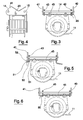
- the winch 10 is solidly constrained to a frame 13 which is connected with play to guides 14 and 15, fixed to the structure of the crane.
- the guides 14 and 15 are fixed to the crane structure by connecting plates 40 and 41 which are shaped so that their upper shape can be easily welded to the main boom of the crane.
- the frame 13 comprises a support plate 45, to which the winch is fixed by front screws 60b and 60c, and back screws 60a and 60d, which engage a frame 18 arranged on the upper part of the winch 10.
- Two lateral plates 42 and 43 are fixed vertically to the sides of the support plate and are arranged parallel to the connecting plates 40 and 41 and are provided with holes in which the guides 14 and 15 insert.
- connection system between the winch 10 and the crane structure is normally used in known cranes and is therefore preferable.
- the connection with play between the winch and the crane structure could however be achieved differently.
- the device comprises means for detecting, of known type, which are excited by the pulling of the cable 11 on the frame 13 and which, by opposing the movements between the frame 13 and the structure of the crane, provide a command signal which is proportional to the stresses generated following contact between the frame and the structure of the crane.
- connection with play the frame is able to perform small movements, generally speaking of the order of a few tenths of a millimetre, generated by pulling the cable; these movements are however opposed by the means for detecting which, following opposition to the movements, generate the command signal.
- the connection with play has therefore the aim of making the crane not rigidly solidly constrained to the crane structure; further, in this way any eventual deformations of the crane structure due to movements of the booms or the sections (and not to the pull on the cable) do not get transferred to the winch and therefore do not generate stresses that influence the signal generated by the means for detecting.
- the means for detecting comprise at least one load cell, of known type, which generates an electric command signal which is proportional to the compression, generated by the traction on the cable 11, to which the cell is subjected following its compression between the frame 13 and the crane structure.
- a load cell 20 is provided, located between the connecting plate 40 and the side plate 42 which are in a position comprised between the winch 10 and the pulley 16.
- the cell 20 opposes and stops the frame 13 from moving along the guides; in this way the pull on the cable causes a compression force between the plate 42 and the plate 40 of the load cell 20 which therefore generates a signal which is proportional to the entity of the compression.
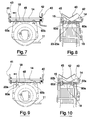
- a pivot 50 is provided, arranged between the connecting plate 41 and the side plate 43 which are in an external position to the zone comprised between the winch 10 and the pulley 16 (the opposite plates to the plates 40 and 42 of the first embodiment).
- the pivot fixed to the plate 43, is slidable with respect to the plate 41 and is provided with a stop 52, arranged on the external part of the plate 41, which has the function of constraining.
- This embodiment includes a load cell 21 arranged between the stop 52 and the plate 41.
- the load cell 21 opposes and prevents the frame 13 from moving along the guides.
- the pulling of the cable causes a compression stress on the load cell 21 between the plate 41 and the stop 52, which load cell 21 thus generates a signal which is proportional to the entity of the compression force.
- the means for detecting can be a load cell 23 or a linear transducer 23a which are fixed to the frame 18 of the winch 10 in such a way as to be in contact with the lower part of the support plate 45; the load cell 23 or the transducer 23a are arranged between the back screws 60a and 60d.
- the frame 13 can perform small movements of elastic deformation. If the cell is a load cell 23, it opposes the small movements, so that a pull of the cable causes flexion of the frame 18 and a consequent compression force on the load cell 23, located between the frame 18 and the lower part of the support plate 45, the load cell 23 then emitting a signal which is proportional to the entity of the compression force.
- the transducer 23a moves following the small movements; in this way a pull on the cable causes flexion of the frame 18 and the transducer 23a measures the change in distance between the frame 18 and the lower part of the support plate 45, thus generating a signal which is proportional to the entity of the change.
- the third embodiment has been described with the load cell 23 or the linear transducer 23a arranged between the back screws 60a and 60d, but it would be possible to arrange the cell 23 or the transducer 23a between the front screws 60b and 60c; the only thing that changes is that traction stresses from the cell 23 will be measured (the transducer 23a will still measure a change in the distance, which will be however of opposite entity to the previous one).
- a pair of load cells 22a and 22b are provided, which are each inserted between the heads of the back screws 60a and 60d and the lower part of the frame 18 of the winch 10.
- the frame 18 can make small oscillating movements on the guides, so that the pull of the cable causes flexion in the frame 18 and a consequent compression, between the frame 18 and the heads of the screws 60 and 60d, of the load cells 22a and 22b, which thus generate a signal which is proportional to the entity of the compression.
- the means for detecting comprise a traction sensor of known type which generates an electrical command signal which is proportional to the traction generated by the traction on the cable 11.
- the device comprises a dynamometer 30 which is arranged between the connecting plate 41 and the side plate 43, which are in a position which is external of the zone comprised between the winch 10 and the pulley 16.
- the dynamometer can be of any known type.
- the pull on the cable causes traction, between the plate 43 and the plate 41, of the dynamometer 30 which therefore generates a signal which is proportional to the entity of the traction.
- the signal generated by the above-described means for detecting is used to command activation of the devices of the crane, which activate the booms or the sections.
- the signal exceeds a predetermined value, the signal acts on the devices of the crane which activate the booms or the sections and stop the movement which has generated the compression or traction proportional to the signal.
- the signal generated by the above-described means for detecting is not influenced by any eventual factors due to structural deformation not deriving from the pull on the cable 11, because the winch is not solidly constrained to the structure of the crane and thus is not influenced by the above-cited factors; it only detects those which derive from a pull on the cable 11.
- the device of the invention also exhibits the considerable advantage of providing a signal which can also be used for determining the entity of the load hoisted by the winch, as the pull on the cable 11 generating the signal is proportional to the weight of the load hoisted.
Landscapes
- Engineering & Computer Science (AREA)
- Mechanical Engineering (AREA)
- Jib Cranes (AREA)
- Control And Safety Of Cranes (AREA)
Priority Applications (4)
| Application Number | Priority Date | Filing Date | Title |
|---|---|---|---|
| ES03425403T ES2302909T3 (es) | 2003-06-23 | 2003-06-23 | Grua con un guinche y un dispositivo de control de la traccion. |
| AT03425403T ATE391692T1 (de) | 2003-06-23 | 2003-06-23 | Kran mit einer seilwinde und mit einer zugsteuereinrichtung |
| DE60320241T DE60320241T2 (de) | 2003-06-23 | 2003-06-23 | Kran mit einer Seilwinde und mit einer Zugsteuereinrichtung |
| EP03425403A EP1491485B1 (fr) | 2003-06-23 | 2003-06-23 | Grue avec un treuil ainsi qu' un système de commande de traction |
Applications Claiming Priority (1)
| Application Number | Priority Date | Filing Date | Title |
|---|---|---|---|
| EP03425403A EP1491485B1 (fr) | 2003-06-23 | 2003-06-23 | Grue avec un treuil ainsi qu' un système de commande de traction |
Publications (2)
| Publication Number | Publication Date |
|---|---|
| EP1491485A1 true EP1491485A1 (fr) | 2004-12-29 |
| EP1491485B1 EP1491485B1 (fr) | 2008-04-09 |
Family
ID=33396128
Family Applications (1)
| Application Number | Title | Priority Date | Filing Date |
|---|---|---|---|
| EP03425403A Expired - Lifetime EP1491485B1 (fr) | 2003-06-23 | 2003-06-23 | Grue avec un treuil ainsi qu' un système de commande de traction |
Country Status (4)
| Country | Link |
|---|---|
| EP (1) | EP1491485B1 (fr) |
| AT (1) | ATE391692T1 (fr) |
| DE (1) | DE60320241T2 (fr) |
| ES (1) | ES2302909T3 (fr) |
Cited By (3)
| Publication number | Priority date | Publication date | Assignee | Title |
|---|---|---|---|---|
| US8875912B2 (en) | 2010-06-17 | 2014-11-04 | Palfinger Ag | Vehicle crane |
| EP3502036A1 (fr) * | 2017-12-20 | 2019-06-26 | Cargotec Patenter AB | Dispositif de guidage de câble |
| IT202300001827A1 (it) * | 2023-02-06 | 2024-08-06 | Jacques Tranchero | Gru con un sistema di limitazione di tiro del verricello. |
Citations (6)
| Publication number | Priority date | Publication date | Assignee | Title |
|---|---|---|---|---|
| FR2292659A1 (fr) * | 1974-11-28 | 1976-06-25 | Tax Hans | Systeme de securite a surcharge pour grue pivotante a fleche a inclinaison variable |
| US4003482A (en) * | 1972-11-27 | 1977-01-18 | Societe Anonyme Dite: Potain Poclain Materiel | Safety device for a crane |
| WO1998055388A1 (fr) * | 1997-06-03 | 1998-12-10 | William Hook Limited | Appareil de controle de securite |
| EP1134178A2 (fr) * | 2000-03-10 | 2001-09-19 | FASSI GRU IDRAULICHE S.p.A. | Dispositif de fin de course pour grues de levage, en particulier grues avec flèches télescopiques |
| EP1291312A2 (fr) * | 2001-09-05 | 2003-03-12 | Allebroer Leo Alix De Lille | Dispositif de manutention d'une charge |
| EP1308414A1 (fr) * | 2001-10-30 | 2003-05-07 | Brevini Winches S.p.A. | Treuil avec détecteur de surcharge |
-
2003
- 2003-06-23 DE DE60320241T patent/DE60320241T2/de not_active Expired - Lifetime
- 2003-06-23 ES ES03425403T patent/ES2302909T3/es not_active Expired - Lifetime
- 2003-06-23 AT AT03425403T patent/ATE391692T1/de active
- 2003-06-23 EP EP03425403A patent/EP1491485B1/fr not_active Expired - Lifetime
Patent Citations (6)
| Publication number | Priority date | Publication date | Assignee | Title |
|---|---|---|---|---|
| US4003482A (en) * | 1972-11-27 | 1977-01-18 | Societe Anonyme Dite: Potain Poclain Materiel | Safety device for a crane |
| FR2292659A1 (fr) * | 1974-11-28 | 1976-06-25 | Tax Hans | Systeme de securite a surcharge pour grue pivotante a fleche a inclinaison variable |
| WO1998055388A1 (fr) * | 1997-06-03 | 1998-12-10 | William Hook Limited | Appareil de controle de securite |
| EP1134178A2 (fr) * | 2000-03-10 | 2001-09-19 | FASSI GRU IDRAULICHE S.p.A. | Dispositif de fin de course pour grues de levage, en particulier grues avec flèches télescopiques |
| EP1291312A2 (fr) * | 2001-09-05 | 2003-03-12 | Allebroer Leo Alix De Lille | Dispositif de manutention d'une charge |
| EP1308414A1 (fr) * | 2001-10-30 | 2003-05-07 | Brevini Winches S.p.A. | Treuil avec détecteur de surcharge |
Cited By (4)
| Publication number | Priority date | Publication date | Assignee | Title |
|---|---|---|---|---|
| US8875912B2 (en) | 2010-06-17 | 2014-11-04 | Palfinger Ag | Vehicle crane |
| EP3502036A1 (fr) * | 2017-12-20 | 2019-06-26 | Cargotec Patenter AB | Dispositif de guidage de câble |
| IT202300001827A1 (it) * | 2023-02-06 | 2024-08-06 | Jacques Tranchero | Gru con un sistema di limitazione di tiro del verricello. |
| WO2024165962A1 (fr) * | 2023-02-06 | 2024-08-15 | Jacques Tranchero | Grue dotée d'un système de limitation de la traction du treuil |
Also Published As
| Publication number | Publication date |
|---|---|
| DE60320241D1 (de) | 2008-05-21 |
| EP1491485B1 (fr) | 2008-04-09 |
| ES2302909T3 (es) | 2008-08-01 |
| DE60320241T2 (de) | 2009-05-14 |
| ATE391692T1 (de) | 2008-04-15 |
Similar Documents
| Publication | Publication Date | Title |
|---|---|---|
| CN101746675B (zh) | 起重机超起装置及其控制系统和控制方法 | |
| CA2076949C (fr) | Dispositif indicateur de moment de charge | |
| US10472214B2 (en) | Crane and method for monitoring the overload protection of such a crane | |
| WO2018014466A1 (fr) | Dispositif de réglage de hauteur de marteau-pilon servant à la détection d'une contrainte élevée d'une fondation sur pieux | |
| US20140330481A1 (en) | Device and Method for Ascertaining and Monitoring an Assembled Counterweight on a Crane | |
| CN104444882B (zh) | 卷扬系统及包括该卷扬系统的起重机 | |
| AU2016330336B2 (en) | Drum-type conveying installation with cable-monitoring device | |
| CN118579661A (zh) | 一种重物起吊防摆动的稳定起重装置 | |
| CN113677614B (zh) | 起重机 | |
| EP1491485B1 (fr) | Grue avec un treuil ainsi qu' un système de commande de traction | |
| JPH09216786A (ja) | 油圧クレーンのブーム伸縮停止保持装置 | |
| CN216662334U (zh) | 预紧装置、臂架组件及起重机 | |
| KR100416395B1 (ko) | 크레인 과부하 방지장치 | |
| KR101121689B1 (ko) | 크레인 하중센서 | |
| CN213625488U (zh) | 荷载精确测量型固定卷扬启闭机 | |
| KR102365185B1 (ko) | 붐길이센서가 설치되는 유압식크레인 다단붐 장치의 붐 길이 검출장치 | |
| CN105035977B (zh) | 腰绳装置、臂架支承装置和起重机 | |
| CN112299259B (zh) | 一种起升绕绳系统及塔式起重机 | |
| US11492235B2 (en) | Measuring device for load measurement in a hoist | |
| RU48183U1 (ru) | Ограничитель нагрузки грузоподъемного крана | |
| CN219058380U (zh) | 一种履带起重机 | |
| CN217201739U (zh) | 一种具有过载保护功能的门式起重机 | |
| CN219771596U (zh) | 一种活动桅杆自动顶升伺服控制系统及起重机 | |
| CN222023920U (zh) | 一种吊装起重器的防护装置 | |
| US11964850B2 (en) | Crane |
Legal Events
| Date | Code | Title | Description |
|---|---|---|---|
| PUAI | Public reference made under article 153(3) epc to a published international application that has entered the european phase |
Free format text: ORIGINAL CODE: 0009012 |
|
| AK | Designated contracting states |
Kind code of ref document: A1 Designated state(s): AT BE BG CH CY CZ DE DK EE ES FI FR GB GR HU IE IT LI LU MC NL PT RO SE SI SK TR |
|
| AX | Request for extension of the european patent |
Extension state: AL LT LV MK |
|
| 17P | Request for examination filed |
Effective date: 20050314 |
|
| AKX | Designation fees paid |
Designated state(s): AT BE BG CH CY CZ DE DK EE ES FI FR GB GR HU IE IT LI LU MC NL PT RO SE SI SK TR |
|
| AXX | Extension fees paid |
Extension state: LV Payment date: 20050314 Extension state: LT Payment date: 20050314 |
|
| 17Q | First examination report despatched |
Effective date: 20060929 |
|
| RAP1 | Party data changed (applicant data changed or rights of an application transferred) |
Owner name: FASSI GRU S.P.A. |
|
| 17Q | First examination report despatched |
Effective date: 20060929 |
|
| GRAP | Despatch of communication of intention to grant a patent |
Free format text: ORIGINAL CODE: EPIDOSNIGR1 |
|
| GRAS | Grant fee paid |
Free format text: ORIGINAL CODE: EPIDOSNIGR3 |
|
| GRAA | (expected) grant |
Free format text: ORIGINAL CODE: 0009210 |
|
| AK | Designated contracting states |
Kind code of ref document: B1 Designated state(s): AT BE BG CH CY CZ DE DK EE ES FI FR GB GR HU IE IT LI LU MC NL PT RO SE SI SK TR |
|
| AX | Request for extension of the european patent |
Extension state: LT LV |
|
| REG | Reference to a national code |
Ref country code: GB Ref legal event code: FG4D |
|
| RIN1 | Information on inventor provided before grant (corrected) |
Inventor name: TAGLIAFERRI, IVAN Inventor name: GUIDOROSSI, ARCHILLE Inventor name: SIGNORI, ROBERTO Inventor name: CERESOLI, ROSSANO |
|
| REG | Reference to a national code |
Ref country code: CH Ref legal event code: EP |
|
| REG | Reference to a national code |
Ref country code: IE Ref legal event code: FG4D |
|
| REF | Corresponds to: |
Ref document number: 60320241 Country of ref document: DE Date of ref document: 20080521 Kind code of ref document: P |
|
| REG | Reference to a national code |
Ref country code: SE Ref legal event code: TRGR |
|
| REG | Reference to a national code |
Ref country code: ES Ref legal event code: FG2A Ref document number: 2302909 Country of ref document: ES Kind code of ref document: T3 |
|
| LTIE | Lt: invalidation of european patent or patent extension |
Effective date: 20080409 |
|
| PG25 | Lapsed in a contracting state [announced via postgrant information from national office to epo] |
Ref country code: SI Free format text: LAPSE BECAUSE OF FAILURE TO SUBMIT A TRANSLATION OF THE DESCRIPTION OR TO PAY THE FEE WITHIN THE PRESCRIBED TIME-LIMIT Effective date: 20080409 |
|
| NLV1 | Nl: lapsed or annulled due to failure to fulfill the requirements of art. 29p and 29m of the patents act | ||
| PG25 | Lapsed in a contracting state [announced via postgrant information from national office to epo] |
Ref country code: NL Free format text: LAPSE BECAUSE OF FAILURE TO SUBMIT A TRANSLATION OF THE DESCRIPTION OR TO PAY THE FEE WITHIN THE PRESCRIBED TIME-LIMIT Effective date: 20080409 Ref country code: FI Free format text: LAPSE BECAUSE OF FAILURE TO SUBMIT A TRANSLATION OF THE DESCRIPTION OR TO PAY THE FEE WITHIN THE PRESCRIBED TIME-LIMIT Effective date: 20080409 Ref country code: BG Free format text: LAPSE BECAUSE OF FAILURE TO SUBMIT A TRANSLATION OF THE DESCRIPTION OR TO PAY THE FEE WITHIN THE PRESCRIBED TIME-LIMIT Effective date: 20080709 Ref country code: PT Free format text: LAPSE BECAUSE OF FAILURE TO SUBMIT A TRANSLATION OF THE DESCRIPTION OR TO PAY THE FEE WITHIN THE PRESCRIBED TIME-LIMIT Effective date: 20080909 |
|
| ET | Fr: translation filed | ||
| PG25 | Lapsed in a contracting state [announced via postgrant information from national office to epo] |
Ref country code: CZ Free format text: LAPSE BECAUSE OF FAILURE TO SUBMIT A TRANSLATION OF THE DESCRIPTION OR TO PAY THE FEE WITHIN THE PRESCRIBED TIME-LIMIT Effective date: 20080409 Ref country code: MC Free format text: LAPSE BECAUSE OF NON-PAYMENT OF DUE FEES Effective date: 20080630 Ref country code: DK Free format text: LAPSE BECAUSE OF FAILURE TO SUBMIT A TRANSLATION OF THE DESCRIPTION OR TO PAY THE FEE WITHIN THE PRESCRIBED TIME-LIMIT Effective date: 20080409 |
|
| REG | Reference to a national code |
Ref country code: CH Ref legal event code: PL |
|
| PLBE | No opposition filed within time limit |
Free format text: ORIGINAL CODE: 0009261 |
|
| STAA | Information on the status of an ep patent application or granted ep patent |
Free format text: STATUS: NO OPPOSITION FILED WITHIN TIME LIMIT |
|
| PG25 | Lapsed in a contracting state [announced via postgrant information from national office to epo] |
Ref country code: SK Free format text: LAPSE BECAUSE OF FAILURE TO SUBMIT A TRANSLATION OF THE DESCRIPTION OR TO PAY THE FEE WITHIN THE PRESCRIBED TIME-LIMIT Effective date: 20080409 Ref country code: RO Free format text: LAPSE BECAUSE OF FAILURE TO SUBMIT A TRANSLATION OF THE DESCRIPTION OR TO PAY THE FEE WITHIN THE PRESCRIBED TIME-LIMIT Effective date: 20080409 Ref country code: BE Free format text: LAPSE BECAUSE OF FAILURE TO SUBMIT A TRANSLATION OF THE DESCRIPTION OR TO PAY THE FEE WITHIN THE PRESCRIBED TIME-LIMIT Effective date: 20080409 |
|
| 26N | No opposition filed |
Effective date: 20090112 |
|
| GBPC | Gb: european patent ceased through non-payment of renewal fee |
Effective date: 20080709 |
|
| PG25 | Lapsed in a contracting state [announced via postgrant information from national office to epo] |
Ref country code: EE Free format text: LAPSE BECAUSE OF FAILURE TO SUBMIT A TRANSLATION OF THE DESCRIPTION OR TO PAY THE FEE WITHIN THE PRESCRIBED TIME-LIMIT Effective date: 20080409 Ref country code: IE Free format text: LAPSE BECAUSE OF NON-PAYMENT OF DUE FEES Effective date: 20080623 |
|
| PG25 | Lapsed in a contracting state [announced via postgrant information from national office to epo] |
Ref country code: LI Free format text: LAPSE BECAUSE OF NON-PAYMENT OF DUE FEES Effective date: 20080630 Ref country code: GB Free format text: LAPSE BECAUSE OF NON-PAYMENT OF DUE FEES Effective date: 20080709 Ref country code: CH Free format text: LAPSE BECAUSE OF NON-PAYMENT OF DUE FEES Effective date: 20080630 |
|
| PG25 | Lapsed in a contracting state [announced via postgrant information from national office to epo] |
Ref country code: CY Free format text: LAPSE BECAUSE OF FAILURE TO SUBMIT A TRANSLATION OF THE DESCRIPTION OR TO PAY THE FEE WITHIN THE PRESCRIBED TIME-LIMIT Effective date: 20080409 |
|
| PG25 | Lapsed in a contracting state [announced via postgrant information from national office to epo] |
Ref country code: LU Free format text: LAPSE BECAUSE OF NON-PAYMENT OF DUE FEES Effective date: 20080623 Ref country code: HU Free format text: LAPSE BECAUSE OF FAILURE TO SUBMIT A TRANSLATION OF THE DESCRIPTION OR TO PAY THE FEE WITHIN THE PRESCRIBED TIME-LIMIT Effective date: 20081010 |
|
| PG25 | Lapsed in a contracting state [announced via postgrant information from national office to epo] |
Ref country code: TR Free format text: LAPSE BECAUSE OF FAILURE TO SUBMIT A TRANSLATION OF THE DESCRIPTION OR TO PAY THE FEE WITHIN THE PRESCRIBED TIME-LIMIT Effective date: 20080409 |
|
| PG25 | Lapsed in a contracting state [announced via postgrant information from national office to epo] |
Ref country code: GR Free format text: LAPSE BECAUSE OF FAILURE TO SUBMIT A TRANSLATION OF THE DESCRIPTION OR TO PAY THE FEE WITHIN THE PRESCRIBED TIME-LIMIT Effective date: 20080710 |
|
| REG | Reference to a national code |
Ref country code: FR Ref legal event code: PLFP Year of fee payment: 14 |
|
| REG | Reference to a national code |
Ref country code: FR Ref legal event code: PLFP Year of fee payment: 15 |
|
| REG | Reference to a national code |
Ref country code: FR Ref legal event code: PLFP Year of fee payment: 16 |
|
| PGFP | Annual fee paid to national office [announced via postgrant information from national office to epo] |
Ref country code: SE Payment date: 20220622 Year of fee payment: 20 Ref country code: IT Payment date: 20220609 Year of fee payment: 20 |
|
| PGFP | Annual fee paid to national office [announced via postgrant information from national office to epo] |
Ref country code: AT Payment date: 20220621 Year of fee payment: 20 |
|
| PGFP | Annual fee paid to national office [announced via postgrant information from national office to epo] |
Ref country code: FR Payment date: 20220623 Year of fee payment: 20 |
|
| PGFP | Annual fee paid to national office [announced via postgrant information from national office to epo] |
Ref country code: ES Payment date: 20220712 Year of fee payment: 20 Ref country code: DE Payment date: 20220628 Year of fee payment: 20 |
|
| REG | Reference to a national code |
Ref country code: DE Ref legal event code: R071 Ref document number: 60320241 Country of ref document: DE |
|
| REG | Reference to a national code |
Ref country code: ES Ref legal event code: FD2A Effective date: 20230630 |
|
| PG25 | Lapsed in a contracting state [announced via postgrant information from national office to epo] |
Ref country code: ES Free format text: LAPSE BECAUSE OF EXPIRATION OF PROTECTION Effective date: 20230624 |
|
| REG | Reference to a national code |
Ref country code: SE Ref legal event code: EUG |
|
| REG | Reference to a national code |
Ref country code: AT Ref legal event code: MK07 Ref document number: 391692 Country of ref document: AT Kind code of ref document: T Effective date: 20230623 |